EP4307100A1 - Schaltgerät - Google Patents
Schaltgerät Download PDFInfo
- Publication number
- EP4307100A1 EP4307100A1 EP23184538.9A EP23184538A EP4307100A1 EP 4307100 A1 EP4307100 A1 EP 4307100A1 EP 23184538 A EP23184538 A EP 23184538A EP 4307100 A1 EP4307100 A1 EP 4307100A1
- Authority
- EP
- European Patent Office
- Prior art keywords
- display
- switching apparatus
- user
- computer systems
- pointer icon
- Prior art date
- Legal status (The legal status is an assumption and is not a legal conclusion. Google has not performed a legal analysis and makes no representation as to the accuracy of the status listed.)
- Withdrawn
Links
Images


Classifications
-
- G—PHYSICS
- G06—COMPUTING OR CALCULATING; COUNTING
- G06F—ELECTRIC DIGITAL DATA PROCESSING
- G06F3/00—Input arrangements for transferring data to be processed into a form capable of being handled by the computer; Output arrangements for transferring data from processing unit to output unit, e.g. interface arrangements
- G06F3/01—Input arrangements or combined input and output arrangements for interaction between user and computer
- G06F3/02—Input arrangements using manually operated switches, e.g. using keyboards or dials
- G06F3/023—Arrangements for converting discrete items of information into a coded form, e.g. arrangements for interpreting keyboard generated codes as alphanumeric codes, operand codes or instruction codes
-
- G—PHYSICS
- G06—COMPUTING OR CALCULATING; COUNTING
- G06F—ELECTRIC DIGITAL DATA PROCESSING
- G06F3/00—Input arrangements for transferring data to be processed into a form capable of being handled by the computer; Output arrangements for transferring data from processing unit to output unit, e.g. interface arrangements
- G06F3/14—Digital output to display device ; Cooperation and interconnection of the display device with other functional units
- G06F3/1423—Digital output to display device ; Cooperation and interconnection of the display device with other functional units controlling a plurality of local displays, e.g. CRT and flat panel display
- G06F3/1446—Digital output to display device ; Cooperation and interconnection of the display device with other functional units controlling a plurality of local displays, e.g. CRT and flat panel display display composed of modules, e.g. video walls
-
- G—PHYSICS
- G06—COMPUTING OR CALCULATING; COUNTING
- G06F—ELECTRIC DIGITAL DATA PROCESSING
- G06F3/00—Input arrangements for transferring data to be processed into a form capable of being handled by the computer; Output arrangements for transferring data from processing unit to output unit, e.g. interface arrangements
- G06F3/14—Digital output to display device ; Cooperation and interconnection of the display device with other functional units
-
- G—PHYSICS
- G06—COMPUTING OR CALCULATING; COUNTING
- G06F—ELECTRIC DIGITAL DATA PROCESSING
- G06F3/00—Input arrangements for transferring data to be processed into a form capable of being handled by the computer; Output arrangements for transferring data from processing unit to output unit, e.g. interface arrangements
- G06F3/01—Input arrangements or combined input and output arrangements for interaction between user and computer
- G06F3/03—Arrangements for converting the position or the displacement of a member into a coded form
- G06F3/033—Pointing devices displaced or positioned by the user, e.g. mice, trackballs, pens or joysticks; Accessories therefor
- G06F3/038—Control and interface arrangements therefor, e.g. drivers or device-embedded control circuitry
-
- G—PHYSICS
- G06—COMPUTING OR CALCULATING; COUNTING
- G06F—ELECTRIC DIGITAL DATA PROCESSING
- G06F3/00—Input arrangements for transferring data to be processed into a form capable of being handled by the computer; Output arrangements for transferring data from processing unit to output unit, e.g. interface arrangements
- G06F3/01—Input arrangements or combined input and output arrangements for interaction between user and computer
- G06F3/048—Interaction techniques based on graphical user interfaces [GUI]
- G06F3/0481—Interaction techniques based on graphical user interfaces [GUI] based on specific properties of the displayed interaction object or a metaphor-based environment, e.g. interaction with desktop elements like windows or icons, or assisted by a cursor's changing behaviour or appearance
- G06F3/04812—Interaction techniques based on cursor appearance or behaviour, e.g. being affected by the presence of displayed objects
-
- G—PHYSICS
- G09—EDUCATION; CRYPTOGRAPHY; DISPLAY; ADVERTISING; SEALS
- G09G—ARRANGEMENTS OR CIRCUITS FOR CONTROL OF INDICATING DEVICES USING STATIC MEANS TO PRESENT VARIABLE INFORMATION
- G09G3/00—Control arrangements or circuits, of interest only in connection with visual indicators other than cathode-ray tubes
- G09G3/20—Control arrangements or circuits, of interest only in connection with visual indicators other than cathode-ray tubes for presentation of an assembly of a number of characters, e.g. a page, by composing the assembly by combination of individual elements arranged in a matrix no fixed position being assigned to or needed to be assigned to the individual characters or partial characters
- G09G3/2092—Details of a display terminals using a flat panel, the details relating to the control arrangement of the display terminal and to the interfaces thereto
-
- G—PHYSICS
- G09—EDUCATION; CRYPTOGRAPHY; DISPLAY; ADVERTISING; SEALS
- G09G—ARRANGEMENTS OR CIRCUITS FOR CONTROL OF INDICATING DEVICES USING STATIC MEANS TO PRESENT VARIABLE INFORMATION
- G09G5/00—Control arrangements or circuits for visual indicators common to cathode-ray tube indicators and other visual indicators
- G09G5/003—Details of a display terminal, the details relating to the control arrangement of the display terminal and to the interfaces thereto
- G09G5/006—Details of the interface to the display terminal
-
- G—PHYSICS
- G09—EDUCATION; CRYPTOGRAPHY; DISPLAY; ADVERTISING; SEALS
- G09G—ARRANGEMENTS OR CIRCUITS FOR CONTROL OF INDICATING DEVICES USING STATIC MEANS TO PRESENT VARIABLE INFORMATION
- G09G2354/00—Aspects of interface with display user
-
- G—PHYSICS
- G09—EDUCATION; CRYPTOGRAPHY; DISPLAY; ADVERTISING; SEALS
- G09G—ARRANGEMENTS OR CIRCUITS FOR CONTROL OF INDICATING DEVICES USING STATIC MEANS TO PRESENT VARIABLE INFORMATION
- G09G2356/00—Detection of the display position w.r.t. other display screens
-
- G—PHYSICS
- G09—EDUCATION; CRYPTOGRAPHY; DISPLAY; ADVERTISING; SEALS
- G09G—ARRANGEMENTS OR CIRCUITS FOR CONTROL OF INDICATING DEVICES USING STATIC MEANS TO PRESENT VARIABLE INFORMATION
- G09G2370/00—Aspects of data communication
- G09G2370/20—Details of the management of multiple sources of image data
-
- G—PHYSICS
- G09—EDUCATION; CRYPTOGRAPHY; DISPLAY; ADVERTISING; SEALS
- G09G—ARRANGEMENTS OR CIRCUITS FOR CONTROL OF INDICATING DEVICES USING STATIC MEANS TO PRESENT VARIABLE INFORMATION
- G09G2370/00—Aspects of data communication
- G09G2370/24—Keyboard-Video-Mouse [KVM] switch
Definitions
- This invention relates generally to computer switching systems.
- Known forms of computer user control devices include mice, keyboards, roller balls and touch pads. Each such control device allows a user to move a pointer on one or more displays so as to provide an input/command to cause a computer to perform a required function.
- multiple, distinct computer systems may be accessible to a user by way of one or more displays and the user control device, in which a user is able to use any of said multiple host systems with the user control device (and the visible output from each system is provided on the one or more displays, hereinafter referred to as the 'visual display apparatus').
- Each such computer system may include a PC, MAC, laptop, server, personal electronic device (PED), and more broadly any data processor device or computer device which provides an output responsive to a user's input.
- PED personal electronic device
- Each computer system may be located local to the visual display apparatus and user control device, or remotely therefrom.
- Each such system may be physically distinct from the one or more other computer systems.
- Each such computer system may host one or more (software) applications, which perform respective functions, such as access to and manipulation or processing of data.
- a switching apparatus for allowing a user to provide an input to select which one of multiple computer systems a user input apparatus provides commands to, and the visual display apparatus is arranged to display a respective display output of each of multiple computer systems, and wherein, the switching apparatus arranged to bring about a selection signal which is indicative to the user of which computer system the user input apparatus is connected to.
- the selection signal may include a visual and/or audio and/or haptic signal.
- a haptic signal may include a vibration or 'buzz' output, or which can otherwise be sensed by touch.
- the switching apparatus may be configured to allow a user controlled position of a pointer icon on a visual display apparatus to determine which one of multiple computer systems a user input apparatus provides commands to.
- the switching apparatus may be viewed as determining or selecting which computer system to connect input signals from the user input device to based at least on a determined position of the pointer icon on the visual display apparatus.
- ⁇ Pointer icon' is to be interpreted broadly as including a moveable graphical image used to activate or control certain elements in a graphic user interface of an application or an operating system, and indicates where in the graphic user interface an action is to be performed, such as opening a file, selecting text and activating a function. It will be appreciated that a pointer icon need not be arrow-shaped, and could be of any shape or two-dimensional form or graphic manifestation.
- the material displayed which is output to the display apparatus by the computer systems may include text, graphics, pictures, and video material, for example.
- the selection signal may comprise a coloured border.
- the selection signal may comprise an icon or symbol.
- the selection signal may comprise a change in the visible attributes of displayed material, such as a change in colour or tone of text and/or a change in colour or tone of a background on which material is displayed.
- the selection signal may be the same, or substantially the same, for the selection of some or each of the display outputs.
- the selection signal may differ for each of the output displays.
- a visual selection signal may be provided by the visual display apparatus, and specifically by the respective display output.
- a visual selection signal may include generating a visual signal at or proximal to a periphery or border of a display output.
- the selection signal may be static or may be intermittent or dynamic (such as flashing).
- a selection signal may include a pattern or an array of shapes, and/or may include text.
- the selection signal may be generated for all, or substantially all, of the duration for which the pointer icon is positioned within a respective display output (until it is caused to be moved to another respective display output by the user).
- the selection signal may be generated for only part of duration for which the pointer icon is positioned within a particular display output. For example, the selection signal may be generated for a predetermined time after the pointer icon enters a different display output. Thereafter, the selection signal may be generated only when the user moves the pointer (within a currently selected display output) and/or generates a command input to the respective computer system, which may be for a predetermined time, and not for the full duration of the pointer icon being in a display output).
- the selection signal may be generated only in respect of the display output into which the pointer icon has been positioned, and not in respect of any other display outputs.
- the visual display apparatus may comprise multiple display units, in which each display unit may provide a respective display output for a computer system.
- the visual display apparatus may comprise a (unitary) display unit in which a display area, and more specifically a display screen, is divided into regions, such as into two regions (such as two halves), or into four regions (such as four quadrants). Each region may provide a respective display output for a computer system. This may be achieved by assigning different groups of pixels (each group defining a region) for different display outputs.
- Such a display unit may be termed a common, or shared, visual display device.
- the visual display apparatus may comprise a combination of (unitary and physically distinct) display units, each such unit providing a respective one display output, and a display unit which provides multiple display outputs, with each of multiple display outputs assigned a particular region of the display area of the (latter) display unit.
- the visual display apparatus may comprise one or more display screens or monitors.
- the switching apparatus may be configured to allow a user to select which and/or how many of the computer system display outputs are visible to the user.
- the switching apparatus may allow for a user to move between a first subset of display outputs being displayed and a second subset of display outputs being displayed and vice versa. There may be more two selectable subsets. Where a single visual display unit is used, the user can select which subset of display outputs is displayed by the unit.
- the switching apparatus may be arranged to cause the display output of one or more non-selected computer systems to be partially or substantially obscured or obfuscated, so that any displayed text or other displayed material, is less visually discernible as compared to when any of said non-selected computer systems is selected.
- the obfuscation may include overlaying or superimposing a pattern or tone over the displayed material.
- the obfuscation may include applying a blurring of the displayed material.
- the obfuscation may include reducing the clarity or brightness of displayed material.
- non-active display outputs The display outputs of computer systems which are not selected at any one time may be referred to as non-active display outputs.
- the switching apparatus may include a switch which is controllable to determine which of the two or more computer systems the user provides inputs to.
- the switching apparatus may be incorporated or integrated into the display apparatus, or may be a device which is separate therefrom.
- the switching apparatus may be arranged to monitor the position, or change in position, of the pointer icon.
- the switching apparatus may be arranged to receive signals indicative of the same. More generally the switching apparatus may be arranged to determine or receive signals indicative of at least one of: a position of the pointer icon, a change in position of the pointer icon, when the pointer icon has been moved out of a display output and a display output to which the pointer icon has been moved.
- the switching apparatus may comprise a processor.
- the processor may be arranged to receive signals from the computer systems indicative of when the pointer has been controlled to be moved out of the display output boundary of a respective computer system.
- the processor may directly monitor the position of the pointer on the display screen, and thereby determine which of the computer systems user inputs are to be directed to.
- the switching apparatus may comprise an input port which is arranged to be connected to the user input device.
- the switching apparatus may include one or more input ports which are arranged to be connected to one or more computer systems.
- the switching apparatus may comprise an output which is arranged to be connected to the display apparatus.
- the switching apparatus may be considered as providing multiple selectable channels between the user input apparatus and the computer systems, wherein by determining in which display output the pointer is positioned, a respective connection is made.
- the switching apparatus may be arranged to perform a switch in connections from the user input apparatus and a first computer system to connection between said user input apparatus and a second computer system when the pointer icon passes a boundary which delineates the display output associated with the first computer system to the display output of the second computer system, where the first and second display outputs are adjacent.
- a dedicated device (which may be additional to any keyboard or mouse or trackpad) for selecting which computer system is connected for user input.
- Each attached computer system may have a dedicated button.
- switching between different computer systems may be implemented by function keys, or by keys pressed in a particular sequence or simultaneously.
- Computer system switching may be achieved by mouse or trackpad commands in which the user presses a predetermined combination of one more mouse/trackpad buttons which the switch can interpret as a command to switch to a different computer system.
- the switching apparatus may be configured to reposition the pointer icon in the respective display output in response to a user input, and position the pointer icon at a predetermined position in the selected display output.
- the user input apparatus may comprise at least one of:
- a computer network comprising:
- the multiple computer systems may not be (directly) connected to one another, including in relation to direct transfer of data.
- Each computer system may be viewed as a distinct and separate domain. This includes that it is not possible for a user to select material shown in one display output to a location in another.
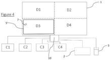
- FIG. 1 there is shown a novel computer network which comprises a display screen 1, a keyboard 2, mouse 3, multiple computer systems C1, C2, C3 and C4.
- the display screen 1 comprises a switch 10 which is arranged to connect the keyboard and mouse to one of the computer systems, dependent on which part of the display screen a pointer icon is located.
- the display screen 1 comprises a display area which is divided into four quadrants, D1, D2, D3 and D4.
- D1, D2, D3 and D4 is a display output of a respective computer system.
- each of D1 to D4 occupies its own (or is mapped onto a) set of pixels, which is defined and contained within a boundary (which is shared with an adjacent display output). It is not necessary that there is any physical border or partition between the quadrants (such as bezels).
- the display screen 1 comprises connector ports to which each of the computer systems is connected.
- the display screen 1 also comprises connector ports arranged to receive connectors of the keyboard 2 and the mouse 3, which allow a user to provide control signals to a selected one of the computer systems.
- FIG. 2 shows the switching apparatus 10, which comprises a processor 12, a memory and a switch S, as well as various interconnections as shown.
- the processor is configured to provide a control signal to the switch S. This is achieved by the monitoring of the position of the pointer icon, and determining in which quadrant it is positioned at any one time.
- the processor 12 is provided with a connection from the switch S (selectively) to each computer system as shown by the broken lines. Each connection allows the inputs from either of the keyboard 2 or the mouse 3 to be sent to a respective computer system.
- the switching apparatus 10 is provided with machine executable instructions which enable the signals and data from the computer systems to be shown on the display screen, and more specifically for the output from each respective computer system to be shown in a respective quadrant.
- a user may determine to which quadrant each computer system is assigned (or this may be done automatically in accordance with preconfigured set-up instructions).
- the instructions allow also the instantaneous position of the pointer icon to be monitored and to control the switch S accordingly.
- the instructions additionally bring about a selection signal which provides an indication output to the user as to which of the computer systems is connected to the mouse and keyboard, as a result of the user moving the pointer icon from one quadrant to another.
- Said instructions may be provided as a software mat or be embodied in firmware, or the like/similar, and may be termed a driver or an operating system.
- the connections provided between the output displays and the computer systems may be seen as creating four channels, with the keyboard 2 and the mouse 3 being selectively connectable to a required channel.
- the switching apparatus may be viewed as providing a routing functionality in which input signals from the keyboard 2 and the mouse 3 are routed dependent on which computer system has selected at any particular moment.
- D1, D2, D3 and D4 are of the same size, in an alternative embodiment one or some may be of different sizes (i.e. dimensions) to the others.
- D1 and D2 become the output display of the first computer system
- D3 and D4 are the output displays of the second and third systems.
- pointer icon positioning information could be obtained from the relevant computer system.
- the pointer icon movement activity brought about by the user could be monitored by a currently selected computer system, for example by comparing the absolute mouse pointer position with the size of the respective output display.
- the host computer determines that the position of the pointer icon has passed a boundary of the respective output display, this is communicated to the switching apparatus.
- FIG. 3 the user has controlled the mouse 3 to position a pointer icon 7 into the output display D2, which provides visual output for the computer system C2.
- the switching apparatus causes a selection signal 5 to be shown, which is a coloured border which is adjacent to the defining periphery of D2. This provides a clear visual indication to the user that they are connected to computer system C2.
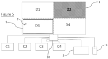
- Figure 5 shows a further embodiment.
- the output display D2 which is non-active as shown (since the pointer icon is in D3), and has applied to it an obfuscation.
- a pattern of diagonal lines is applied which causes the material presented by D2 to be fully or partially indiscernible (or discernible with difficulty). It may be that the computer system C2, which is connected to D2, contains sensitive data. If the user causes the pointer to move back to D2, then the obfuscation is removed, and the selection signal re-applied.
- a selection signal (and / or any obfuscation) may be caused to be generated as part of the data sent by one some or all of the computer systems when the pointer icon passes from one output display to another, as opposed to this being part of the functionality of the switching apparatus.
- the switching apparatus may monitor the position of the pointer icon, and signal to a relevant computer system when the pointer icon is positioned in its domain.
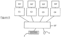
- FIG. 6 shows a computer network in which each of computer systems C1, C2, C3 and C4 has a its own monitor D1', D2', D3' and D4', which monitors are positioned side-by-side.
- a switching apparatus 10' is provided which is a separate unit to the monitors and to the computer systems, and the switching apparatus 10' comprises a number of ports or connectors which allow the computer systems to be connected to the switching apparatus 10' .
- the switching apparatus implements the same or similar functionality to that described above in relation to the switching apparatus 10.
- the pointer icon When, for example, the user causes the pointer icon to re-position pointer to an adjacent monitor the pointer appears to jump the gap between the display screens.
- the pointer icon may be caused to appear at a predetermined position (such as a central position) in the ⁇ new' display monitor when its position is caused to exceed the area of the previous monitor.
- the switching device may be arranged to allow a user some degree of user-configurability, which may include selecting preferred characteristics (be they visual, audio and/haptic) of how selected display outputs and non-active outputs are indicated to the user.
- the computer systems are separate in their own rights, and are not connected to one another such that there is data separation between them.
- Each computer system may be viewed having its own (data) domain which is distinct from domains of other of the computer systems.
- This characteristic includes that it is not normally possible to use a cut-and-paste or copy function to transfer material (such as text) shown in one output display to a location in another (despite the fact that this may appear to possible, especially when there are multiple display outputs (each from a different computer system) shown on different regions of a single visual display unit), and there is a single/common user input device (such as a mouse and a keyboard).
- the user may be able to configure how a selected computer system is shown as being selected and/or how non-selected computer systems are indicated to the user.
- Each computer system may be viewed as a data domain, and in the above embodiments the user is advantageously able to differentiate, to the user, by data domain.
Landscapes
- Engineering & Computer Science (AREA)
- Theoretical Computer Science (AREA)
- General Engineering & Computer Science (AREA)
- Physics & Mathematics (AREA)
- General Physics & Mathematics (AREA)
- Human Computer Interaction (AREA)
- Computer Hardware Design (AREA)
- Multimedia (AREA)
- Digital Computer Display Output (AREA)
- Input From Keyboards Or The Like (AREA)
Applications Claiming Priority (1)
| Application Number | Priority Date | Filing Date | Title |
|---|---|---|---|
| GB2210437.6A GB2620636A (en) | 2022-07-15 | 2022-07-15 | Switching apparatus |
Publications (1)
| Publication Number | Publication Date |
|---|---|
| EP4307100A1 true EP4307100A1 (de) | 2024-01-17 |
Family
ID=84540101
Family Applications (1)
| Application Number | Title | Priority Date | Filing Date |
|---|---|---|---|
| EP23184538.9A Withdrawn EP4307100A1 (de) | 2022-07-15 | 2023-07-10 | Schaltgerät |
Country Status (3)
| Country | Link |
|---|---|
| US (1) | US20250013411A1 (de) |
| EP (1) | EP4307100A1 (de) |
| GB (1) | GB2620636A (de) |
Citations (4)
| Publication number | Priority date | Publication date | Assignee | Title |
|---|---|---|---|---|
| US20130038674A1 (en) * | 2011-08-08 | 2013-02-14 | Xtreme Labs Inc. | System and method for distributing and interacting with images in a network |
| EP2682859A2 (de) * | 2012-07-06 | 2014-01-08 | LG Electronics, Inc. | Mobiles Endgerät, Bildanzeigevorrichtung und Verfahren zur Bereitstellung einer Benutzerschnittstelle damit |
| US20150077369A1 (en) * | 2013-09-17 | 2015-03-19 | Ricoh Company, Ltd. | Information processing apparatus and information processing system |
| US20200065053A1 (en) * | 2017-05-02 | 2020-02-27 | Barco N.V. | Presentation server, data relay method and method for generating virtual pointer |
Family Cites Families (8)
| Publication number | Priority date | Publication date | Assignee | Title |
|---|---|---|---|---|
| US6469690B1 (en) * | 2000-04-20 | 2002-10-22 | International Business Machines Corporation | Data sharing for multi-CPU mouse/keyboard switcher |
| US7545361B2 (en) * | 2005-04-28 | 2009-06-09 | International Business Machines Corporation | Automatically switching input and display devices between multiple workstations |
| US20070152972A1 (en) * | 2006-01-05 | 2007-07-05 | Aten International Co., Ltd. | KVM switch system capable of invoking OSD menu by dedicated key |
| US20080062121A1 (en) * | 2006-09-08 | 2008-03-13 | Aten Interational Co., Ltd. | Shuttle control system for controlling kvm switch and method thereof |
| US7917674B2 (en) * | 2008-10-21 | 2011-03-29 | Aten International Co., Ltd. | KVM switch with PIP functions using remote desktop sharing technique |
| US20100097326A1 (en) * | 2008-10-21 | 2010-04-22 | Liang yu-ting | Keyboard-video-mouse switch system with interactive display |
| TWI757762B (zh) * | 2020-06-04 | 2022-03-11 | 宏正自動科技股份有限公司 | 多視窗顯示的切換方法以及切換系統 |
| CN113467866A (zh) * | 2021-03-31 | 2021-10-01 | 联想(北京)有限公司 | 处理方法及装置 |
-
2022
- 2022-07-15 GB GB2210437.6A patent/GB2620636A/en active Pending
-
2023
- 2023-07-05 US US18/347,011 patent/US20250013411A1/en not_active Abandoned
- 2023-07-10 EP EP23184538.9A patent/EP4307100A1/de not_active Withdrawn
Patent Citations (4)
| Publication number | Priority date | Publication date | Assignee | Title |
|---|---|---|---|---|
| US20130038674A1 (en) * | 2011-08-08 | 2013-02-14 | Xtreme Labs Inc. | System and method for distributing and interacting with images in a network |
| EP2682859A2 (de) * | 2012-07-06 | 2014-01-08 | LG Electronics, Inc. | Mobiles Endgerät, Bildanzeigevorrichtung und Verfahren zur Bereitstellung einer Benutzerschnittstelle damit |
| US20150077369A1 (en) * | 2013-09-17 | 2015-03-19 | Ricoh Company, Ltd. | Information processing apparatus and information processing system |
| US20200065053A1 (en) * | 2017-05-02 | 2020-02-27 | Barco N.V. | Presentation server, data relay method and method for generating virtual pointer |
Also Published As
| Publication number | Publication date |
|---|---|
| GB2620636A (en) | 2024-01-17 |
| GB202210437D0 (en) | 2022-08-31 |
| US20250013411A1 (en) | 2025-01-09 |
Similar Documents
| Publication | Publication Date | Title |
|---|---|---|
| US10091456B2 (en) | On-screen display systems | |
| US8473654B2 (en) | Computer input switching device | |
| JP5023217B2 (ja) | 複数のコンピュータを管理する装置及びシステム | |
| US5790127A (en) | Supervising activations states in application sharing | |
| US9542006B2 (en) | Secure KM switch | |
| US7770131B2 (en) | Subsystem, shared-control apparatus and method | |
| US20060048062A1 (en) | Software and method providing graphic user interface for graphics adapter configuration | |
| US7168049B2 (en) | System and method for allocating computing resources | |
| US20140223490A1 (en) | Apparatus and method for intuitive user interaction between multiple devices | |
| EP2431854A2 (de) | Bildanzeigevorrichtung, Bildanzeigesystem und Bildanzeigeverfahren | |
| CN101551739B (zh) | 切换器及屏幕显示系统与方法 | |
| GB2314245A (en) | Graphical user interface | |
| US7496846B2 (en) | Computer presentation and command integration apparatus | |
| KR20020010863A (ko) | 가상 데스크탑들간의 전환 | |
| US20170255357A1 (en) | Display control device | |
| EP4307100A1 (de) | Schaltgerät | |
| JPH0818948A (ja) | ビデオ監視制御方法及び装置 | |
| AU2013310588B2 (en) | Display control method, computer program, display control device and image display system | |
| US20100315328A1 (en) | Integrated control system with multiple media sources and corresponding displays | |
| US20090251413A1 (en) | Computer Switching Device | |
| Rodgers et al. | Smart sticky widgets: Pseudo-haptic enhancements for multi-monitor displays | |
| GB2323738A (en) | Video signal mixing device | |
| JP5718105B2 (ja) | 切替器 | |
| US20070018963A1 (en) | Tablet hot zones | |
| KR101535415B1 (ko) | 듀얼 컴퓨터의 디스플레이 제어시스템 |
Legal Events
| Date | Code | Title | Description |
|---|---|---|---|
| PUAI | Public reference made under article 153(3) epc to a published international application that has entered the european phase |
Free format text: ORIGINAL CODE: 0009012 |
|
| STAA | Information on the status of an ep patent application or granted ep patent |
Free format text: STATUS: THE APPLICATION HAS BEEN PUBLISHED |
|
| AK | Designated contracting states |
Kind code of ref document: A1 Designated state(s): AL AT BE BG CH CY CZ DE DK EE ES FI FR GB GR HR HU IE IS IT LI LT LU LV MC ME MK MT NL NO PL PT RO RS SE SI SK SM TR |
|
| STAA | Information on the status of an ep patent application or granted ep patent |
Free format text: STATUS: REQUEST FOR EXAMINATION WAS MADE |
|
| 17P | Request for examination filed |
Effective date: 20240717 |
|
| RBV | Designated contracting states (corrected) |
Designated state(s): AL AT BE BG CH CY CZ DE DK EE ES FI FR GB GR HR HU IE IS IT LI LT LU LV MC ME MK MT NL NO PL PT RO RS SE SI SK SM TR |
|
| STAA | Information on the status of an ep patent application or granted ep patent |
Free format text: STATUS: EXAMINATION IS IN PROGRESS |
|
| 17Q | First examination report despatched |
Effective date: 20250103 |
|
| STAA | Information on the status of an ep patent application or granted ep patent |
Free format text: STATUS: THE APPLICATION HAS BEEN WITHDRAWN |
|
| 18W | Application withdrawn |
Effective date: 20250331 |