EP4307623A2 - Procédé et dispositif de transmission de données, support de stockage et dispositif électronique - Google Patents
Procédé et dispositif de transmission de données, support de stockage et dispositif électronique Download PDFInfo
- Publication number
- EP4307623A2 EP4307623A2 EP23205724.0A EP23205724A EP4307623A2 EP 4307623 A2 EP4307623 A2 EP 4307623A2 EP 23205724 A EP23205724 A EP 23205724A EP 4307623 A2 EP4307623 A2 EP 4307623A2
- Authority
- EP
- European Patent Office
- Prior art keywords
- symbols
- dft
- symbol pairs
- conjugate
- symbol
- Prior art date
- Legal status (The legal status is an assumption and is not a legal conclusion. Google has not performed a legal analysis and makes no representation as to the accuracy of the status listed.)
- Pending
Links
Images





Classifications
-
- H—ELECTRICITY
- H04—ELECTRIC COMMUNICATION TECHNIQUE
- H04L—TRANSMISSION OF DIGITAL INFORMATION, e.g. TELEGRAPHIC COMMUNICATION
- H04L25/00—Baseband systems
- H04L25/02—Details ; arrangements for supplying electrical power along data transmission lines
- H04L25/0202—Channel estimation
- H04L25/0224—Channel estimation using sounding signals
-
- H—ELECTRICITY
- H04—ELECTRIC COMMUNICATION TECHNIQUE
- H04L—TRANSMISSION OF DIGITAL INFORMATION, e.g. TELEGRAPHIC COMMUNICATION
- H04L5/00—Arrangements affording multiple use of the transmission path
- H04L5/003—Arrangements for allocating sub-channels of the transmission path
- H04L5/0044—Allocation of payload; Allocation of data channels, e.g. PDSCH or PUSCH
-
- H—ELECTRICITY
- H04—ELECTRIC COMMUNICATION TECHNIQUE
- H04L—TRANSMISSION OF DIGITAL INFORMATION, e.g. TELEGRAPHIC COMMUNICATION
- H04L27/00—Modulated-carrier systems
- H04L27/26—Systems using multi-frequency codes
- H04L27/2601—Multicarrier modulation systems
- H04L27/2602—Signal structure
- H04L27/2605—Symbol extensions, e.g. Zero Tail, Unique Word [UW]
-
- H—ELECTRICITY
- H04—ELECTRIC COMMUNICATION TECHNIQUE
- H04L—TRANSMISSION OF DIGITAL INFORMATION, e.g. TELEGRAPHIC COMMUNICATION
- H04L27/00—Modulated-carrier systems
- H04L27/26—Systems using multi-frequency codes
- H04L27/2601—Multicarrier modulation systems
- H04L27/2602—Signal structure
- H04L27/261—Details of reference signals
- H04L27/2613—Structure of the reference signals
- H04L27/26132—Structure of the reference signals using repetition
-
- H—ELECTRICITY
- H04—ELECTRIC COMMUNICATION TECHNIQUE
- H04L—TRANSMISSION OF DIGITAL INFORMATION, e.g. TELEGRAPHIC COMMUNICATION
- H04L27/00—Modulated-carrier systems
- H04L27/26—Systems using multi-frequency codes
- H04L27/2601—Multicarrier modulation systems
- H04L27/2626—Arrangements specific to the transmitter only
- H04L27/2627—Modulators
- H04L27/2628—Inverse Fourier transform modulators, e.g. inverse fast Fourier transform [IFFT] or inverse discrete Fourier transform [IDFT] modulators
-
- H—ELECTRICITY
- H04—ELECTRIC COMMUNICATION TECHNIQUE
- H04L—TRANSMISSION OF DIGITAL INFORMATION, e.g. TELEGRAPHIC COMMUNICATION
- H04L27/00—Modulated-carrier systems
- H04L27/26—Systems using multi-frequency codes
- H04L27/2601—Multicarrier modulation systems
- H04L27/2626—Arrangements specific to the transmitter only
- H04L27/2627—Modulators
- H04L27/2634—Inverse fast Fourier transform [IFFT] or inverse discrete Fourier transform [IDFT] modulators in combination with other circuits for modulation
- H04L27/2636—Inverse fast Fourier transform [IFFT] or inverse discrete Fourier transform [IDFT] modulators in combination with other circuits for modulation with FFT or DFT modulators, e.g. standard single-carrier frequency-division multiple access [SC-FDMA] transmitter or DFT spread orthogonal frequency division multiplexing [DFT-SOFDM]
-
- H—ELECTRICITY
- H04—ELECTRIC COMMUNICATION TECHNIQUE
- H04L—TRANSMISSION OF DIGITAL INFORMATION, e.g. TELEGRAPHIC COMMUNICATION
- H04L27/00—Modulated-carrier systems
- H04L27/26—Systems using multi-frequency codes
- H04L27/2601—Multicarrier modulation systems
- H04L27/2647—Arrangements specific to the receiver only
- H04L27/2649—Demodulators
- H04L27/265—Fourier transform demodulators, e.g. fast Fourier transform [FFT] or discrete Fourier transform [DFT] demodulators
-
- H—ELECTRICITY
- H04—ELECTRIC COMMUNICATION TECHNIQUE
- H04L—TRANSMISSION OF DIGITAL INFORMATION, e.g. TELEGRAPHIC COMMUNICATION
- H04L5/00—Arrangements affording multiple use of the transmission path
- H04L5/003—Arrangements for allocating sub-channels of the transmission path
- H04L5/0048—Allocation of pilot signals, i.e. of signals known to the receiver
-
- H—ELECTRICITY
- H04—ELECTRIC COMMUNICATION TECHNIQUE
- H04L—TRANSMISSION OF DIGITAL INFORMATION, e.g. TELEGRAPHIC COMMUNICATION
- H04L5/00—Arrangements affording multiple use of the transmission path
- H04L5/0001—Arrangements for dividing the transmission path
- H04L5/0003—Two-dimensional division
- H04L5/0005—Time-frequency
- H04L5/0007—Time-frequency the frequencies being orthogonal, e.g. OFDM(A) or DMT
Definitions
- the present disclosure relates to the field of communication, and for example, to a data transmission method and device, a storage medium, and an electronic device.
- Channel estimation accuracy greatly influences demodulation performance.
- Channel estimation accuracy is usually influenced by a pilot solution and a channel estimation method.
- a channel estimation method in a related art has the following shortcoming.
- a pilot occupies a certain time-frequency resource and serves as a kind of overhead.
- SNR Signal Noise Ratio
- pilot collision seriously impairs the grant-free access performance.
- more pilots are usually required to be designed to reduce the collision probability, and more pilots usually means that more time-frequency resources need to be occupied by the pilots and the pilot detection complexity is higher.
- Embodiments of the present disclosure provide a data transmission method and device, a storage medium, and an electronic device, to solve the problems of time-frequency resource waste and inaccurate channel estimation caused by a pilot collision in the related art.
- a data transmission method which may include that: M conjugate symbol pairs are generated, where M is more than or equal to 1; and the symbol pairs in the conjugate relationship are transmitted.
- another data transmission method may include that: M symbols [ d 0 ,d 1 ,...d M-1 ] are generated; the M symbols [ d 0 ,d 1 ,...d M-1 ] are converted to generate M symbols [ e 0 ,e 1 ,...e M-1 ]; and [ d 0 ,d 1 ,...d M-1 ] and [ e 0 ,e 1 ,...e M-1 ] are transmitted, where M is more than or equal to 1.
- another data transmission method may include that: M conjugate symbol pairs are received, where M is more than or equal to 1; and channel estimation is performed by use of the symbol pairs.
- a data transmission device which may include: a generation module, configured to generate M conjugate symbol pairs, where M is more than or equal to 1; and a transmitting module, configured to transmit the conjugate symbol pairs.
- another data transmission device may include: a first generation module, configured to generate M symbols [ d 0 ,d 1 ,...d M-1 ]; a second generation module, configured to convert the M symbols [ d 0 ,d 1 ,...d M-1 ] to generate M symbols [ e 0 ,e 1 ,...e M-1 ]; and a transmitting module, configured to transmit [ d 0 ,d 1 ,...d M-1 ] and [ e 0 ,e 1 ,...e M-1 ], where M is more than or equal to 1.
- another data transmission device may include: a receiving module, configured to receive M conjugate symbol pairs, where M is more than or equal to 1; and an estimation module, configured to perform channel estimation by use of the symbol pairs.
- a storage medium in which a computer program may be stored, the computer program being configured to run to execute the method in any abovementioned embodiment.
- an electronic device which may include a memory and a processor.
- a computer program may be stored in the memory.
- the processor may be configured to run the computer program to execute the method in any abovementioned embodiment.
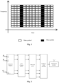
- each cell is a Resource Element (RE) of an OFDM/DFT-S-OFDM/SC-FDMA symbol, i.e., a subcarrier resource of the OFDM/DFT-S-OFDM/SC-FDMA symbol. Since a subcarrier belongs to a frequency domain, an RE may also be called a frequency-domain RE.
- RE Resource Element
- Fig. 2 is a schematic diagram of OFDM modulation according to the related art of the present disclosure.
- Multi-carrier OFDM modulation is shown in Fig. 2 .
- Digital amplitude-phase modulation symbols i.e., xPhase Shift Keying (xPSK)/x Quadrature Amplitude Modulation (xQAM) symbols, for example, Binary Phase Shift Keying (BPSK), Quadrature Phase Shift Keying (QPSK), 16 Quadrature Amplitude Modulation (16QAM)
- each RE directly carries a digital amplitude-phase modulation symbol, or the M digital amplitude-phase modulation symbols are carried in the OFDM symbol (because the OFDM symbol includes the M subcarriers herein), or the OFDM symbol carries the M digital amplitude-phase modulation symbols.
- [] T refers to a transposition operation.
- D [ d 0 ,d 1 ,...d M-1 ] is a digital amplitude-phase modulation symbol and is directly mapped to a subcarrier.
- SC-FDMA modulation may substantially keep high properties of multi-carrier OFDM and may also have the key advantages of low Peak-to-Average Power Radio/Cubic Metric (PAPR/CM) of a single-carrier signal. Therefore, SC-FDMA is adopted as a carrier modulation method for uplink transmission in an LTE standard. The following two SC-FDMA signal generation methods may be adopted.
- Fig. 3 is a schematic diagram of a frequency-domain generation method for an SC-FDMA signal according to the related art of the present disclosure, as shown in Fig. 3 .
- DFT Discrete Fourier Transform
- Fig. 4 is a schematic diagram of a time-domain generation method for an SC-FDMA signal according to the related art of the present disclosure, as shown in Fig. 4 .
- Fig. 3 illustrates a frequency-domain generation method for SC-FDMA, i.e., DFT-S-OFDM modulation.
- the M digital amplitude-phase modulation symbols D [ d 0 ,d 1 ,...d M-1 ] in the DFT-S-OFDM modulation symbol are transmitted in a time domain rather than directly carried in a frequency-domain RE.
- DFT() refers to a DFT-spread transform function or a DFT-spread transform function/operation.
- An accurate operation rule for DFT may be represented with a matrix operation.
- Q is an M ⁇ M matrix, i.e., a square matrix with M rows and M columns.
- Row indexes include a first row to an Mth row
- column indexes include a first column to an Mth column.
- An element in an (n+1)th row and an (m+1)th column is e j 2 ⁇ M nm , where M > m ⁇ 0 and M > n > 0 .
- T refers to the transposition operation.
- Fig. 4 illustrates a time-domain generation method for SC-FDMA. This method involves no DFT and Inverse Fast Fourier Transform (IFFT) operations, is easier to implement and suitable for some scenarios requiring low implementation complexity, and includes two conditions, i.e., a condition in which there is no block duplication and a condition in which there is block duplication.
- IFFT Inverse Fast Fourier Transform
- the M digital amplitude-phase modulation symbols D [ d 0 ,d 1 ,...d M-1 ] are directly transmitted in the time domain rather than directly carried in the RE.
- IDFT Inverse Discrete Fourier Transform
- the frequency-domain generation method i.e., DFT-S-OFDM modulation
- the time-domain generation method and frequency-domain generation method for SC-FDMA are equivalent.
- pilot enhancement design includes that:
- pilot collision greatly influences the detection performance of the multiple users. For reducing the influence of the pilot collision, more pilots are usually required to be designed to reduce the collision probability, and more pilots usually means that more time-frequency resources may be occupied by the pilots and the pilot detection complexity is higher.
- a network architecture in which the embodiment of the present application may be implemented includes a transmitting side and a receiving side.
- the transmitting side transmits data to the receiving side.
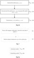
- Fig. 5 is a flowchart of a data transmission method according to an embodiment of the present disclosure. As shown in Fig. 5 , the flow includes operation 502 and operation 504.
- M conjugate symbol pairs are generated, where M is more than or equal to 1.
- the M conjugate symbol pairs are transmitted, and then a receiver may perform channel estimation by use of the symbol pairs, so that the problems of time-frequency resource waste caused by transmitting a specific pilot symbol and inaccurate channel estimation caused by a pilot collision in the related art are solved, and the resource utilization rate is increased.
- an executor of the operations may be, but not limited to, a base station, a terminal or a transmitter, etc.
- the M conjugate symbol pairs include, but not limited to, the following symbol pairs: M directly conjugate symbol pairs; M negatively conjugate symbol pairs; M weighted conjugate symbol pairs; M symbol pairs including A directly conjugate symbol pairs and M-A negatively or weighted conjugate symbol pairs, where A is more than or equal to 1; M symbol pairs including A negatively conjugate symbol pairs and M-A weighted conjugate symbol pairs, where A is more than or equal to 1; M conjugate symbol pairs, obtained by weighting, by use of a weighted value or a weighted vector, one or two symbols in each symbol pair in M directly conjugate symbol pairs; and M conjugate symbol pairs, obtained by weighting, by use of a weighted value or a weighted vector, one or more symbols in multiple symbol pairs in M directly conjugate symbol pairs.
- the M conjugate symbol pairs may be generated in one of the following manners.
- Fig. 6a is a schematic diagram of generating M conjugate symbol pairs according to an embodiment. As shown in Fig. 6a , nine forms are illustrated:
- Spreading processing refers to spreading the symbol by use of a spreading sequence.
- spreading a symbol d by use of a spreading sequence [ c 0 ,c 1 ,...c L-1 ] with a length L refers to an operation of multiplying the symbol d by each element in the spreading sequence to generate L symbols [ d ⁇ c 0 ,d ⁇ c 1 ...d ⁇ c L-1 ].
- conjugation may be performed before permutation, or conjugation may be performed after permutation.
- a value of W is equal to one of M, E, F and G.
- a conjugate of a real number is the real number itself, for the condition that all the modulation symbols are real numbers, for example, BPSK modulation symbols are valued to be -1 or +1 only, the conjugation operation in the embodiment may be omitted. This is because the results obtained by conjugating the real numbers are still the real numbers.
- the method may further include one of the following operations:
- M modulation symbols include BPSK modulation symbols, ⁇ /2 shifted BPSK modulation symbols, QPSK modulation symbols or Quadrature Amplitude Modulation (QAM) symbols. If the M modulation symbols adopt ⁇ /2 shifted BPSK modulation, reduction in a PAPR/CM of a transmitted signal is facilitated better.
- spreading processing is performed on symbols of the conjugate symbol pairs by use of a spreading sequence; or, after the M weighted conjugate symbol pairs are obtained, spreading processing is performed on symbols of the conjugate symbol pairs by use of a spreading sequence.
- the spreading sequence is obtained in one of the following manners: configuration by a system, indication by a receiver of the symbol pairs, independent selection by a transmitter of a sender of the symbol pairs, independent generation by the transmitter of the sender of the symbol pairs, random selection by the transmitter of the sender of the symbol pairs, random generation by the transmitter of the sender of the symbol pairs, and determination by the transmitter of the sender of the symbol pairs according to bits formed by performing Cyclic Redundancy Check (CRC) coding on information bits. That the spreading sequence is, by the transmitter of the sender, independently selected, independently generated, randomly selected or determined according to the bits formed by performing CRC coding on the information bits is a characteristic of grant-free access.
- CRC Cyclic Redundancy Check
- that the spreading sequence is determined according to the bits formed by performing CRC coding on the information bits is favorable for a process that the receiver in a grant-free access solution reconstructs bits that are correctly decoded and eliminates errors. Since all the bits in a CRC codeword are correct after correct decoding and the spreading sequence is determined by the bits of the CRC codeword, determination of the spreading sequence used by the transmitter of the sender may be facilitated.
- the weighted value or the weighted vector is obtained in one of the following manners: configuration by a system, indication by a receiver of the symbol pairs, independent selection by a transmitter of a sender of the symbol pairs, independent generation by the transmitter of the sender of the symbol pairs, random selection by the transmitter of the sender of the symbol pairs, random generation by the transmitter of the sender of the symbol pairs, and determination by the transmitter of the sender of the symbol pairs according to the bits formed by performing CRC coding on the information bits. That the weighted value or the weighted vector is, by the transmitter of the sender, independently selected, independently generated, randomly selected or determined according to the bits formed by performing CRC coding on the information bits is a characteristic of grant-free access.
- weighted value or the weighted vector is determined according to the bits formed by performing CRC coding on the information bits is favorable for the process that the receiver in the grant-free access solution reconstructs the bits that are correctly decoded and eliminates errors. Since all the bits in the CRC codeword are correct after correct decoding and the weighted value or the weighted vector is determined by the bits of the CRC codeword, determination of the weighted value or weighted vector used by the transmitter of the sender may be facilitated.
- the operation that the conjugate symbol pairs are transmitted includes that: the conjugate symbol pairs are carried by use of frequency-domain REs, where two REs respectively carry two symbols in one conjugate symbol pair, and the frequency-domain REs include one of: REs under multi-carrier OFDM modulation, REs under SC-FDMA modulation, and REs under single-carrier DFT-S-OFDM modulation.
- positions of the two REs carrying one conjugate symbol pair are adjacent or at an interval shorter than a predetermined symbol interval.
- the M conjugate symbol pairs include one of: M modulation symbols and M symbols obtained by conjugating the M modulation symbols; and M symbols obtained by performing spreading processing on the B modulation symbols and M symbols obtained by conjugating the M symbols obtained by performing the spreading processing, where B is more than or equal to 1.
- the M conjugate symbol pairs include one of: M symbols obtained by performing DFT on M modulation symbols and M symbols obtained by conjugating the M symbols obtained by performing the DFT; M symbols obtained by performing DFT and spreading processing on the C modulation symbols and M symbols obtained by conjugating the M symbols obtained by performing the DFT and the spreading processing, where C is more than or equal to 1; and M symbols obtained by performing spreading processing and DFT on the D modulation symbols and M symbols obtained by conjugating the M symbols obtained by performing the spreading processing and the DFT, where D is more than or equal to 1.
- the M conjugate symbol pairs include one of: M symbols obtained by performing DFT on M modulation symbols and M symbols obtained by performing DFT after conjugation and permutation of the M modulation symbols; M symbols obtained by performing DFT and spreading processing on the E modulation symbols and M symbols obtained by performing DFT and spreading processing after conjugation and permutation of the E modulation symbols, where E is more than or equal to 1; M symbols obtained by performing spreading processing and DFT on the F modulation symbols and M symbols obtained by performing spreading processing and DFT after conjugation and permutation of the F modulation symbols, where F is more than or equal to 1; and M symbols obtained by performing spreading processing and DFT on the G modulation symbols and M symbols obtained by performing spreading processing, conjugation and permutation, and DFT on the G modulation symbols, where G is more than or equal to 1.
- a conjugate of a real number is the real number itself, for the condition that all the modulation symbols are real numbers, for example, BPSK modulation symbols valued to be -1 or +1 only, the conjugation operation in the embodiment may be omitted. This is because the conjugate of a real number is the real number itself.
- the operation that the conjugate symbol pairs are transmitted includes that: the conjugate symbol pairs are transmitted by use of one antenna of a transmitter.
- the transmitter may have one or more transmitting antennae. If the transmitter has multiple transmitting antennae, it may be applicable to use only one antenna for transmitting; alternatively, it may also be applicable to use multiple antennae for transmitting the same symbol respectively or use multiple antennae for transmitting versions, obtained by weighting through different weighted values, of the same symbol respectively.
- the embodiment On the transmitting side, the embodiment also provides another data transmission method. Referring to Fig. 6b , the flow includes the following operations.
- the M symbols [ d 0 ,d 1 ,...d M-1 ] are transformed to generate M symbols [ e 0 ,e 1 ,...e M-1 ] .
- the operation that the M symbols [ d 0 ,d 1 ,...d M-1 ] are transformed to generate the M symbols [ e 0 ,e 1 ,...e M-1 ] includes one of the following operations:
- the M symbols [ d 0 ,d 1 ,...d M-1 ] are M modulation symbols.
- the M modulation symbols include one of a BPSK modulation symbol, a ⁇ /2 shifted BPSK modulation symbol, a QPSK modulation symbol or a QAM symbol.
- the operation that [ d 0 ,d 1 ,...d M-1 ] and [ e 0 ,e 1 ,...e M-1 ] are transmitted includes one of the following operations:
- the spreading sequence is obtained in one of the following manners: configuration by a system, indication by a receiver of symbol pairs, independent selection by a transmitter of a sender of the symbol pairs, independent generation by the transmitter of the sender of the symbol pairs, random selection by the transmitter of the sender of the symbol pairs, random generation by the transmitter of the sender of the symbol pairs and determination by the transmitter of the sender of the symbol pairs according to bits formed by performing CRC coding on information bits. That the spreading sequence is, by the transmitter of the sender, independently selected, independently generated, randomly selected or determined according to the bits formed by performing CRC coding on the information bits is a characteristic of grant-free access.
- that the spreading sequence is determined according to the bits formed by performing CRC coding on the information bits is favorable for a process that the receiver in a grant-free access solution reconstructs bits that are correctly decoded and eliminates errors. Since all the bits in a CRC codeword are correct after correct decoding and the spreading sequence is determined by the bits of the CRC codeword, determination of the spreading sequence used by the transmitter of the sender may be facilitated.
- the specified value is obtained in one of the following manners: configuration by a system, indication by a receiver of the symbol pairs, independent selection by a transmitter of a sender of the symbol pairs, independent generation by the transmitter of the sender of the symbol pairs, random selection by the transmitter of the sender of the symbol pairs, random generation by the transmitter of the sender of the symbol pairs, and determination by the transmitter of the sender of the symbol pairs according to the bits formed by performing CRC coding on the information bits. That the specified value is, by the transmitter of the sender, independently selected, independently generated, randomly selected or determined according to the bits formed by performing CRC coding on the information bits is a characteristic of grant-free access.
- that the specified value is determined according to the bits formed by performing CRC coding on the information bits is favorable for the process that the receiver in the grant-free access solution reconstructs the bits that are correctly decoded and eliminates errors. Since all the bits in the CRC codeword are correct after correct decoding and the specified value is determined by the bits of the CRC codeword, determination of the specified value used by the transmitter of the sender may be facilitated.
- the operation that [ d 0 ,d 1 ,...d M-1 ] and [ e 0 ,e 1 ,...e M-1 ] are transmitted includes that: [ d 0 ,d 1 ,...d M-1 ] and [ e 0 ,e 1 ,...e M-1 ] are transmitted in one of an SC-FDMA manner and a single-carrier DFT-S-OFDM manner.
- Fig. 7 is a flowchart of another data transmission method according to an embodiment of the present disclosure. The flow is implemented on a receiving side corresponding to Fig. 5 , Fig. 6a or Fig. 6b , and as shown in Fig. 7 , includes operation 702 and operation 704.
- channel estimation is performed by use of the symbol pairs.
- the M conjugate symbol pairs are carried in 2M frequency-domain REs, the REs including one of: REs under multi-carrier OFDM modulation, REs under SC-FDMA modulation, and REs under single-carrier DFT-S-OFDM modulation.
- positions of two REs carrying a symbol pair are adjacent or at an interval shorter than a predetermined symbol interval.
- the method may further include the operation as follows. At least one of the following operations is executed by use of a channel estimation result of channel estimation: channel equalization, demodulation, decoding, and CRC.
- the solution may further include the following operations.
- a first symbol and second symbol corresponding to two symbols of a symbol pair are acquired. The first symbol is multiplied by the second symbol to obtain a square of a channel estimation value, and a root extraction operation is executed on the square of the channel estimation value to obtain the channel estimation value and a negative value of the channel estimation value.
- two obtained equalization results are merged as a first equalization result.
- the computer software product is stored in a storage medium (for example, a Read-Only Memory (ROM)/Random Access Memory (RAM), a magnetic disk and an optical disk), including multiple instructions configured to enable a computer device (which may be a mobile phone, a computer, a server, a network device or the like) to execute the methods in one or more embodiments of the present disclosure.
- a storage medium for example, a Read-Only Memory (ROM)/Random Access Memory (RAM), a magnetic disk and an optical disk
- the embodiment also provides a data transmission device, which is configured to implement the abovementioned embodiment.
- a data transmission device which is configured to implement the abovementioned embodiment.
- module may be a combination of software and/or hardware capable of realizing a preset function.
- the device described in the following embodiment may be implemented with software, implementation with hardware or a combination of the software and the hardware is also possible and conceivable.
- the embodiment provides a structure block diagram of a data transmission device.
- the device is applied to a sender, and as shown in Fig. 8a , includes:
- the M conjugate symbol pairs include one of:
- the M conjugate symbol pairs include one of:
- the conjugation may be performed before the permutation, or the conjugation may be performed after the permutation.
- the spreading processing refers to spreading symbols by use of a spreading sequence.
- a conjugate of a real number is the real number itself, for the condition that all the modulation symbols are real numbers, for example, BPSK modulation symbols valued to be -1 or +1 only, the conjugation operation in the embodiment may be omitted. This is because the conjugate of a real number is the real number itself.
- the embodiment also provides another data transmission device.
- the device includes a first generation module 820, configured to generate M symbols [ d 0 ,d 1 ,...d M-1 ]; a second generation module 822, configured to convert the M symbols [ d 0 ,d 1 ,...d M-1 ] to generate M symbols [ e 0 ,e 1 ,...e M-1 ]; and a transmitting module 824, configured to transmit [ d 0 ,d 1 ,...d M-1 ] and [ e 0 ,e 1 ,...e M-1 ], where M is more than or equal to 1.
- the embodiment provides a structure block diagram of another data transmission device.
- the device is applied to a receiver, and as shown in Fig. 8c , includes: a receiving module 840, configured to receive M conjugate symbol pairs, where M is more than or equal to 1; and an estimation module 840, configured to perform channel estimation by use of the symbol pairs.
- the device for the receiver may further include an execution module, configured to, after the estimation module performs channel estimation by use of the symbol pairs, execute at least one of the following operations by use of a channel estimation result of channel estimation: channel equalization, demodulation, decoding, and CRC.
- an execution module configured to, after the estimation module performs channel estimation by use of the symbol pairs, execute at least one of the following operations by use of a channel estimation result of channel estimation: channel equalization, demodulation, decoding, and CRC.
- Fig. 8d is a structure block diagram of a data transmission system according to an embodiment of the present disclosure. As shown in Fig. 8d , the system includes at least one data transmission device for the sender (Fig. 8d illustrates a scenario of simultaneous connection with two senders) and a data transmission device for the receiver.
- the one or more modules may be implemented through software or hardware and, under the latter condition, may be implemented in, but not limited to, the following manner: the modules are all positioned in the same processor, or the one or more modules are positioned in different processors in any combination form respectively.
- the present application is described according to optional embodiments of the present application and in combination with implementation modes and application scenarios.
- the solution of the embodiment is implemented based on the following characteristics: the effect generated by a channel over transmission symbols in a frequency domain is the conduction of "point multiplication" over transmission symbols.
- point multiplication channels in the frequency domain are strongly correlated in a coherence bandwidth and coherence time, and point multiplication channels experienced by symbols at adjacent or close time of the same or close subcarriers are substantially equal.
- channel refers to generalized channel and includes multipath, as well as time and frequency offsets caused by Doppler and other factors, and the frequency offset causes different phase rotations implemented by point multiplication over RE symbols at different moments.
- Symbols carried in a multi-carrier OFDM or SC-FDMA/DFT-S-OFDM based frequency-domain subcarrier (or RE) may simultaneously include M conjugate symbol pairs, where M is more than or equal to 1.
- Fig. 9 is a schematic diagram of generating conjugate symbol pairs according to an embodiment.
- each cell in the figure is REs under an OFDM/SC-FDMA/DFT-S-OFDM modulation technology
- each RE carries a data symbol
- the symbols carried in two adjacent or close REs (cells) are conjugate or symbols generated by further processing over conjugate symbols, further processing including multiplication by a number or multiplication by a weighted value or phase rotation, etc.
- a kth subcarrier symbol in a symbol sequence S [ s 0 , s 1 ,...
- the figure includes a data symbol s k and s k ⁇ obtained by conjugating the data symbol s k after duplication; or, the data symbol s k and a symbol ⁇ s k ⁇ obtained by conjugating the data symbol s k after duplication and then multiplying a conjugate by minus one; or, the data symbol s k and a symbol js k ⁇ obtained by conjugating the data symbol s k after duplication and then multiplying the conjugate by j.
- s k and s k ⁇ are directly conjugate, s k and ⁇ s k ⁇ are negatively conjugate, and s k and js k ⁇ are weighted conjugate.
- S D
- the method of the embodiment may be simply and directly applied to multi-carrier OFDM only by duplicating a digital amplitude-phase modulation symbol in an RE and then performing conjugation.
- conjugating the symbol block D means conjugating each element in the symbol block.
- Fig. 10 is a schematic diagram of conjugation for multi-carrier OFDM modulation according to an embodiment, as shown in Fig.
- D and D * are directly mapped to M subcarriers of two adjacent or close multi-carrier OFDM symbols, and D and D* may adopt different sequences, or in other words, D and D * may be subjected to permutation.
- the method of the embodiment may be applied to SC-FDMA/DFT-S-OFDM because a low PAPR/CM of a transmitted signal may be ensured and reduction in the cost of a transmitter and enlargement of coverage are facilitated.
- a digital amplitude-phase modulation symbol is carried in a time domain rather than directly carried in a frequency-domain subcarrier, so that only duplicating and conjugating the digital amplitude-phase modulation symbol in the time domain may not ensure a duplicate conjugate relationship in the frequency-domain subcarrier. Therefore, if a conjugation method for DFT-S-OFDM-SC-FDMA, processing on the transmitting side is slightly more complex than multi-carrier OFDM.
- a frequency-domain generation method for SC-FDMA i.e., DFT-S-OFDM
- DFT-S-OFDM because frequency-domain symbols carried in a frequency-domain subcarrier/frequency-domain RE may be explicitly generated in a signal generation process of the frequency-domain generation method, like multi-carrier OFDM, the symbols in the frequency-domain subcarrier may be directly duplicated for conjugation, namely frequency-domain symbols S generated by performing DFT on "time-domain modulation symbols D" may be directly conjugated.
- Fig. 11 is a schematic diagram of a conjugate symbol pair generation method based on a DFT-S-OFDM time-domain generation method according to an embodiment.
- Fig. 11 is a schematic diagram of a conjugate symbol pair generation method based on a DFT-S-OFDM time-domain generation method according to an embodiment.
- S and S * are generated by a DFT-S-OFDM based conjugate symbol pair generation method 1
- S and S * are transmitted through adjacent or close symbols, and S and S* are carried in the frequency domain.
- D and D r ⁇ are generated by a DFT-S-OFDM based conjugate symbol pair generation method 2
- D and D r ⁇ are transmitted through adjacent or close symbols, and D and D r ⁇ are carried in the frequency domain.
- D r ⁇ d 0 ⁇ , d 1 ⁇ ... d M ⁇ 1 ⁇ , namely D r ⁇ is a symbol sequence generated after operations of "conjugation and permutation to a negative sequence" are executed on D.
- DFT() refers to a DFT-spread function or a DFT-spread function/operation.
- An accurate operation rule for DFT may be represented with a matrix operation.
- Q is an M ⁇ M matrix, i.e., a square matrix with M rows and M columns. Row indexes from 1 to M, and column indexes from 1 to M.
- An element in an (n+1)th row and an (m+1)th column is e j 2 ⁇ M nm , M > m ⁇ 0 and M > n ⁇ 0 .
- T refers to a transposition operation.
- the time-domain symbol D may be conjugated and permuted to the negative sequence at first.
- Fig. 12 is a schematic diagram of a conjugate symbol pair generation method based on an SC-FDMA time-domain generation method according to an embodiment. However, the method is more applicable to the time-domain generation method because the generation process is simpler and more direct, as shown in Fig. 12 .
- the method of conjugating the "time-domain symbol” and permuting the "time-domain symbol” to the negative sequence requires one more DFT operation, compared with the method of directly conjugating the frequency-domain symbol, as shown in Fig. 11 .
- D [ d 0 ,d 1 ,...d M- 1 ] are digital amplitude-phase modulation symbols
- D r ⁇ d 0 ⁇ , d 1 ⁇ ... d M ⁇ 1 ⁇ is a symbol sequence generated after the operations of "conjugation and permutation to the negative sequence" are executed on D
- D and D r ⁇ are modulated to (be carried in) two adjacent or close SC-FDMA symbols, or D and D r ⁇ are transmitted through two adjacent or close SC-FDMA symbols.
- the time-domain symbol D may also be conjugated and permuted to an opposite sequence at first.
- DFT(D) and DFT D n ⁇ are conjugate to a certain extent, although not directly conjugate.
- cyclic shift includes cyclic left shift or cyclic right shift.
- a conjugate of a real number is the real number itself, for the condition that all the modulation symbols are real numbers, for example, BPSK modulation symbols valued to be -1 or +1 only, the conjugation operation in the embodiment may be omitted. This is because the conjugate of a real number is the real number itself.
- the method of the embodiment may be combined with "DFT-S-OFDM/SC-FDMA applying ⁇ /2-BPSK (pi/2-BPSK) modulation".
- DFT-S-OFDM/SC-FDMA applying ⁇ /2-BPSK (pi/2-BPSK) modulation usually has a lower PAPR/CM and is more favorable for uplink transmission. The following possible variations are included.
- a conjugate data symbol may further be prefixed with a "minus” or multiplied by a number.
- prefixing with the "minus” is equivalent to multiplication by -1, and is a particular case of multiplication by a number.
- Multiplication by a number may be multiplication by another number, for example, [j,-j, exp(j*pi/4), exp(j*pi/3), etc.].
- different conjugate versions may be multiplied by different numbers. For example, the first duplicate conjugate version is multiplied by -1, the second duplicate conjugate is multiplied by i and the third duplicate conjugate is multiplied by -i.
- y ak H 1 s 1 k + H 2 s 2 k + n ak
- H 1 s 1 k + H 2 s 2 k + n ak ⁇ H 1 ⁇ s 1 k + H 2 ⁇ s 2 k ⁇ n bk ⁇ H 1 ⁇ H 1 ⁇ s 1 k + H 2 + H 2 ⁇ s 2 k + n ak ⁇ n bk ⁇
- M conjugate symbol pairs are generated, for example, four symbols generated by prefixing one symbol in four symbols of every two directly conjugate symbol pairs s 2 k + 1 s 2 k + 1 ⁇ s 2 k + 2 s 2 k + 2 ⁇ with a minus, for example, every two conjugate symbol pairs are weighted to obtain s 2 k + 1 , s 2 k + 1 ⁇ , s 2 k + 2 , ⁇ s 2 k + 2 ⁇ , or s 2 k + 1 , ⁇ s 2 k + 1 ⁇ , s 2 k + 2 , s 2 k + 2 ⁇ , or s 2 k + 1 , s 2 k + 1 ⁇ , ⁇ s 2 k + 2 , s 2 k + 2 ⁇ or ⁇ s 2 k + 1 , s 2 k + 1 ⁇ , ⁇ s 2 k + 2 , s 2 k + 2 ⁇ or
- the user 1 uses s 2 k + 1 s 2 k + 1 ⁇ s 2 k + 2 s 2 k + 2 ⁇ and the user 2 uses s 2 k + 1 , s 2 k + 1 ⁇ , s 2 k + 2 , ⁇ s 2 k + 2 ⁇ .
- a base station may assign different weighted values for different users.
- multiple weighting manners may be defined, for example, two different weighting manners are defined, and a terminal randomly selects one of them. For example, one of the following weights may be randomly selected for a conjugate symbol pair of the user:
- the weight selected by the user is required to be known during reconstruction, which requires weight information selected by the user to be included in "codeword bits formed by performing CRC coding on information bits".
- two inclusion manners or weight determination manners may be adopted.
- One bit in the codeword bits formed by performing CRC coding on the information bits may be adopted to determine the specific weight to be selected. For example, if the bit is 0, the first weight is selected, and if the bit is 1, the second weight is selected.
- a certain operation is executed on the codeword bits formed by performing CRC coding on the information bits to generate a bit, if the bit is 0, the first weight is selected, and if the bit is 1, the second weight is selected.
- FIG. 13 is a schematic diagram of positions of a conjugate symbol pair according to an embodiment, as shown in Fig. 13 .
- Fig. 14 is a schematic diagram of spreading after duplication and conjugation according to an embodiment, as shown in Fig. 14 .
- sequence despreading may be Matched Filter-Despreading (MF-Despreading), ZeroForcing-Despreading (ZF-Despreading) and Minimum Mean Square Error-Despreading (MMSE-Despreading).
- the inter-user interference may be maximally suppressed after sequence despreading, a user signal to be demodulated is relatively clean after the inter-user interference is suppressed, and then channel estimation is performed by use of the conjugation method for further equalization and demodulation decoding.
- This is a key of application of the embodiment to a grant-free multiuser access scenario.
- the spreading sequence is, by the transmitter of the sender, independently selected, independently generated, randomly selected or determined according to the bits formed by performing CRC coding on the information bits.
- that the spreading sequence is determined according to the bits formed by performing CRC coding on the information bits is favorable for a process that the receiver in a grant-free access solution reconstructs bits that are correctly decoded and eliminates errors. Since all the bits in a CRC codeword are correct after correct decoding and the spreading sequence is determined by the bits of the CRC codeword, determination of the spreading sequence used by the transmitter of the sender may be facilitated.
- Fig. 15 is a schematic diagram of implementing conjugation in an OFDM modulation process according to an embodiment.
- symbol spreading may refer to spreading a symbol before subcarrier mapping
- symbol spreading may refer to spreading a symbol after subcarrier mapping
- symbol spreading may refer to spreading a symbol after IFFT
- symbol spreading may refer to spreading a symbol added with a cyclic prefix.
- Fig. 16 is a schematic diagram of implementing conjugation in a DFT-S-OFDM modulation process according to an embodiment.
- symbol spreading may refer to spreading a symbol before DFT
- symbol spreading may refer to spreading a symbol after DFT
- symbol spreading may refer to spreading a symbol after subcarrier mapping
- symbol spreading may refer to spreading a symbol after IFFT
- symbol spreading may refer to spreading a symbol added with a cyclic prefix.
- Fig. 17 is a schematic diagram of implementing conjugation in a time-domain generation process for an SC-FDMA signal according to an embodiment.
- symbol spreading may refer to spreading a symbol before frequency translation
- symbol spreading may refer to spreading a symbol after frequency translation
- symbol spreading may refer to spreading a symbol added with a cyclic prefix.
- a transmitted data frame includes a simple duplication of the data symbol, so that only a conjugation operation is additionally executed on the data symbol that is originally simply duplicated when the embodiment is applied.
- the embodiment is applicable to a single-antenna technology and applicable to a single-antenna transmitter. If the transmitter on the transmitting side has only one transmitting antenna, symbols of a signal transmitted through the transmitting antenna in frequency-domain subcarriers may include both a "data symbol” and a "symbol generated by conjugating the data symbol".
- the technology of the embodiment may also be applied.
- the simplest manner is that a signal in each code block or each transmission block is transmitted by use of only one transmitting antenna and the signal is not transmitted through the other antennae.
- Symbols in the signal transmitted through one transmitting antenna in frequency-domain subcarriers may include both a "data symbol” and a "symbol generated by conjugating the data symbol".
- the receiver estimates a channel by multiplication of received symbols (REs) at adjacent or close moments according to a conjugation property.
- REs received symbols
- y k 1 H k 1 ⁇ s k + n k 1
- y k 2 H k 2 ⁇ s k ⁇ + n k 2 ⁇ .
- n ⁇ k H k 1 ⁇ s k ⁇ n k 1 + H k 2 ⁇ s k ⁇ ⁇ n k 2 + n k 1 n k 2 .
- y k 1 y k 2 includes Hk rather than H k finally to be equalized.
- involved y k 1 y k 2 is required to be averaged because n ⁇ k is also averaged and n ⁇ k may be small after averaging.
- the "conjugate symbol pair" is merged. By merging, the SNR of the symbol may be improved.
- Data obtained by performing equalization and merging twice is transmitted for demodulation decoding. If the data is correctly decoded, then it represents that the equalization is performed correctly and the estimate corresponding to the real channel has been adopted for equalization. If the data is incorrectly decoded, then it represents that the equalization is performed incorrectly and a reverse channel has been adopted for equalization. This is the cost of the method of the embodiment, namely the complexity in equalization and demodulation decoding may be increased.
- the plus or minus that the channel is prefixed with may be determined by use of these reference signals, so that the phase ambiguity of +H and -H of channel estimation may be avoided.
- Decoding is required to be performed only once after determination, so that the number of decoding times is reduced. It is to be noted that these reference signals are not general Demodulation Reference Signals (DMRSs) but only for eliminating the phase ambiguity.
- DMRSs Demodulation Reference Signals
- the transmitting side may adopt a convolutional code or a Polar code. This is because decoding of the convolutional code and the Polar code is relatively special, two decoding results may be obtained by performing decoding only once and then performing some processing on bits obtained by decoding, namely a +H equalization result is decoded and a -H equalization result is decoded, and then CRC may be performed twice to judge which is the correct decoding.
- a digital amplitude-phase modulation symbol (for example, BPSK/QPSK/8PSK/16QAM/64QAM) is directly arranged in a frequency-domain subcarrier, and thus the conjugation method may be easily applied.
- a modulation symbol d k and a conjugate d k ⁇ [conjugate of d k ] of the modulation symbol are required to be arranged in two adjacent REs of a subcarrier.
- ODMA Optical Access
- Fig. 18 is a schematic diagram of carrying a data symbol and a pilot symbol in LTE according to an embodiment.
- Fig. 19 is a schematic diagram of carrying a data symbol and a pilot symbol in an NB-loT according to an embodiment.
- an RE in dark grey carries a DMRS.
- channel estimation is performed by use of data, so that a reference signal overhead may be reduced, and the data is transmitted through all REs.
- the RE originally for arranging the reference signal is configured to arrange a symbol in a conjugate data symbol pair and the other symbol in the conjugate data symbol pair is arranged in an adjacent RE.
- the contents carried in the fourth and eleventh OFDM symbols are changed, and no DMRSs but conjugate versions of the digital amplitude-phase modulation symbols in the adjacent OFDM symbols are carried.
- the fourth OFDM symbol carries a conjugate of a third OFDM digital amplitude-phase modulation symbol
- the eleventh OFDM symbol carries a conjugate of a tenth OFDM digital amplitude-phase modulation symbol.
- the receiver may perform channel estimation by use of D 3 and D 3 ⁇ , as well as D 10 and D 10 ⁇ .
- the conjugate symbol pairs are merged to improve the SNR.
- Fig. 19 is a schematic diagram of carrying a data symbol and a pilot symbol in an NB-loT according to an embodiment. Similarly, a mode 1 and mode 2 of a single-tone OFDM transmission manner in an NB-loT standard in Fig. 19 are shown, and conjugate data symbol pairs are adopted for channel estimation instead of reference signals, to improve the spectrum efficiency.
- symbol duplication is originally required to improve the received SNR (the receiver merges duplicate symbols to improve the SNR of the final symbol).
- simple duplication may be replaced with "conjugation after duplication", so that the method of "channel estimation by conjugation" in the embodiment may be applied to a poor coverage scenario to achieve higher channel estimation accuracy.
- Fig. 20 is a schematic diagram of duplicating transmitted symbols according to an embodiment.
- the transmitted symbols are duplicated once, and the 7 OFDM symbols are duplicated once to obtain 14 symbols, so that the SNR of the 7 symbols may be improved by 3dB.
- the receiver may perform channel estimation for further equalization and demodulation decoding by use of the conjugation method only by replacing simple duplication with "conjugation after duplication".
- the spreading technology is further required to be combined in a multiuser scenario.
- the receiver performs despreading at first to suppress the inter-user interference as much as possible, then multiplies the conjugate symbol pairs for channel estimation and, after equalization, merges the duplicate symbols.
- simple duplication may be correspondingly replaced with "conjugation after duplication and then despreading", so that higher conjugation-based channel estimation accuracy may be achieved in the multiuser scenario, as shown in Fig. 14 .
- the solution is applied to single-carrier OFDM transmission, single-carrier OFDM transmission including DFT-S-OFDM and SC-FDMA transmission, including DFT-S-OFDM and SC-FDMA in the LTE standard.
- two DFT-S-OFDM/SC-FDMA symbols in an uplink PRB pair do not carry digital amplitude-phase modulation symbols but are configured to carry DMRS symbols.
- the two DFT-S-OFDM/SC-FDMA symbols are the fourth and eleventh OFDM symbols respectively.
- an index range of the 14 DFT-S-OFDM/SC-FDMA symbols is [1 ⁇ 14].
- the contents carried in the fourth and eleventh DFT-S-OFDM symbols are changed, and no DMRSs but conjugate versions of frequency-domain symbols S in the adjacent DFT-S-OFDM symbols are carried.
- the fourth DFT-S-OFDM symbol carries the conjugate version of the third OFDM frequency-domain symbol S3, i.e., S 3 ⁇ .
- the eleventh DFT-S-OFDM symbol carries the conjugate version of the tenth OFDM frequency-domain symbol S10, i.e., S 10 ⁇ .
- the receiver may perform channel estimation by use of S 3 and S 3 ⁇ , as well as S 10 and S 10 ⁇ .
- the SNR of the 12 symbols s 0 3 , s 1 3 , ... s 11 3 of S 3 may be improved by 3dB.
- the SNR of the 12 symbols s 0 10 , s 1 10 , ... s 11 10 of S 10 may also be improved by 3dB.
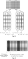
- Fig. 21 is a schematic diagram of a frame structure according to an embodiment.
- the time-domain generation method for SC-FDMA or the frequency-domain generation method i.e., DFT-S-OFDM
- the receiver may perform channel estimation by use of S 3 and S 3 ⁇ , as well as S 10 and S 10 ⁇ , as described above, and then performs equalization, merging and demodulation decoding.
- the final demodulation SNRs of S 3 and S 10 may also be 3dB higher than the other SC-FDMA/DST-S-OFDM frequency-domain symbols. Therefore, the SNR achieved by the modulation manner for D 3 and D 10 is higher than the SNR achieved by another duplication and conjugation free modulation manner, and furthermore, higher spectrum efficiency is achieved.
- a data pilot may be considered to be arranged in the front.
- the frame structure is shown in Fig. 22.
- Fig. 22 is a schematic diagram of another data frame according to an embodiment.
- the transmitted symbols are duplicated once, and the 7 SC-FDMA/DST-S-OFDM symbols are duplicated once to obtain 14 symbols, so that the SNR of the 7 symbols may be improved by 3dB.
- the receiver may perform channel estimation for further equalization and demodulation decoding by use of the conjugation method only by replacing simple duplication with "conjugation after duplication".
- the conjugation method and spreading are combined for application to grant-based multiuser access or grant-free multiuser access. It is applicable to multi-carrier OFDM or single-carrier DST-S-OFDM and SC-FDMA.
- the transmitting side generates two OFDM symbols at first through the conjugation method of the embodiment.
- the OFDM symbols include multi-carrier OFDM or single-carrier DST-S-OFDM/SC-FDMA symbols. Symbols in the same subcarrier of the two OFDM symbols are conjugate. Then, the two OFDM symbols are spread to multiple OFDM symbols by use of the symbol spreading technology.
- the symbols before spreading and after spreading are shown in Fig. 23.
- Fig. 23 is a schematic diagram of spreading conjugate symbols according to an embodiment. In Fig. 23 , each of the 7 OFDM symbols is duplicated and conjugated to generate 14 OFDM symbols, and then the 14 OFDM symbols are spread by use of a sequence with a length 4 one by one to generate 56 OFDM symbols.
- the receiving side reduces the inter-user interference as much as possible by use of the sequence despreading technology (for example, the sequence despreading technology includes MF, ZF and MMSE), and then performs channel estimation by use of the conjugation method of the embodiment for further equalization and demodulation decoding.
- the sequence despreading technology includes MF, ZF and MMSE
- the spreading sequence is, by the transmitter of the sender, independently selected, independently generated, randomly selected or determined according to the bits formed by performing CRC coding on the information bits.
- that the spreading sequence is determined according to the bits formed by performing CRC coding on the information bits is favorable for a process that the receiver in a grant-free access solution reconstructs bits that are correctly decoded and eliminates errors. Since all the bits in a CRC codeword are correct after correct decoding and the spreading sequence is determined by the bits of the CRC codeword, determination of the spreading sequence used by the transmitter of the sender may be facilitated.
- channel estimation is performed by use of no pilot (reference signal) but only data, so that the pilot overhead may be reduced, and the spectrum efficiency may be improved.
- This advantage is achieved for both grant-based and grant-free scenarios, for example, Ultra Low Latency and Reliable Communication (uRLLC) or other conventional Physical Uplink Shared Channel (PUSCH) enhancement.
- uRLLC Ultra Low Latency and Reliable Communication
- PUSCH Physical Uplink Shared Channel
- the working SNR of the grant-based scenario is relatively low and modulation symbol duplication has been required to ensure the performance, the spectrum efficiency and the performance may be improved more obviously by the method of the embodiment.
- the influence of a pilot collision in the grant-free scenario may be avoided. Or, few reference signals are adopted for other purposes. For example, if channel estimation still depends on the data, a small number of reference signals are adopted to avoid the phase ambiguity of +H and -H of channel estimation.
- a conjugate of a real number is the real number itself, for the condition that all the modulation symbols are real numbers, for example, BPSK modulation symbols valued to be -1 or +1 only, the conjugation operation in the embodiment may be omitted. This is because the conjugate of a real number is the real number itself.
- the embodiment of the present disclosure also provides a storage medium, in which a computer program is stored, the computer program being configured to run to execute the method in any embodiment of the present disclosure.
- the storage medium may be configured to store a computer program configured to execute the method in any embodiment of the present disclosure, for example, executing the following operations.
- M conjugate symbol pairs are generated, where M is more than or equal to 1.
- the storage medium may include, but not limited to, one or more media capable of storing computer programs such as a Universal Serial Bus (USB) flash disk, a ROM, a RAM, a mobile hard disk, a magnetic disk or an optical disk.
- USB Universal Serial Bus
- the embodiment of the present disclosure also provides an electronic device, which includes a memory and a processor.
- a computer program is stored in the memory.
- the processor is configured to run the computer program to execute the method in any embodiment of the present disclosure.
- the electronic device may further include a transmission device and an input/output device.
- the transmission device is connected with the processor, and the input/output device is connected with the processor.
- the processor in the embodiment may be configured to execute the following operations through the computer program.
- M conjugate symbol pairs are generated, where M is more than or equal to 1.
- one or more modules or one or more operations of the present disclosure may be implemented through a universal computing device. They may be concentrated in a single computing device or distributed in a network formed by multiple computing devices. In an embodiment, they may be implemented by program codes executable for the computing devices and thus may be stored in a storage device for execution with the computing devices. Moreover, in some cases, the shown or described operations may be executed in sequences different from those described here, or may form one or more integrated circuit modules respectively, or multiple modules or operations therein may form a single integrated circuit module for implementation. The present disclosure is not limited to any specific hardware and software combination.
Landscapes
- Engineering & Computer Science (AREA)
- Signal Processing (AREA)
- Computer Networks & Wireless Communication (AREA)
- Physics & Mathematics (AREA)
- Discrete Mathematics (AREA)
- General Physics & Mathematics (AREA)
- Mathematical Physics (AREA)
- Power Engineering (AREA)
- Digital Transmission Methods That Use Modulated Carrier Waves (AREA)
- Error Detection And Correction (AREA)
- Detection And Prevention Of Errors In Transmission (AREA)
Applications Claiming Priority (4)
| Application Number | Priority Date | Filing Date | Title |
|---|---|---|---|
| CN201810011799 | 2018-01-05 | ||
| CN201810425568.6A CN110011948B (zh) | 2018-01-05 | 2018-05-04 | 数据传输方法及装置、存储介质、电子装置 |
| PCT/CN2019/070491 WO2019134689A1 (fr) | 2018-01-05 | 2019-01-04 | Procédé et dispositif de transmission de données, support d'informations et dispositif électronique |
| EP19735957.3A EP3737059A4 (fr) | 2018-01-05 | 2019-01-04 | Procédé et dispositif de transmission de données, support d'informations et dispositif électronique |
Related Parent Applications (1)
| Application Number | Title | Priority Date | Filing Date |
|---|---|---|---|
| EP19735957.3A Division EP3737059A4 (fr) | 2018-01-05 | 2019-01-04 | Procédé et dispositif de transmission de données, support d'informations et dispositif électronique |
Publications (2)
| Publication Number | Publication Date |
|---|---|
| EP4307623A2 true EP4307623A2 (fr) | 2024-01-17 |
| EP4307623A3 EP4307623A3 (fr) | 2024-04-10 |
Family
ID=67144061
Family Applications (1)
| Application Number | Title | Priority Date | Filing Date |
|---|---|---|---|
| EP23205724.0A Pending EP4307623A3 (fr) | 2018-01-05 | 2019-01-04 | Procédé et dispositif de transmission de données, support de stockage et dispositif électronique |
Country Status (2)
| Country | Link |
|---|---|
| EP (1) | EP4307623A3 (fr) |
| WO (1) | WO2019134689A1 (fr) |
Families Citing this family (1)
| Publication number | Priority date | Publication date | Assignee | Title |
|---|---|---|---|---|
| CN113938174B (zh) * | 2021-10-18 | 2024-04-12 | 哈尔滨工业大学 | 时域两分量wfrft信号传输与合并方法 |
Family Cites Families (8)
| Publication number | Priority date | Publication date | Assignee | Title |
|---|---|---|---|---|
| US7272108B2 (en) * | 2002-08-01 | 2007-09-18 | Mediatek, Inc. | Channel estimation in orthogonal frequency-division multiplexing (OFDM) systems |
| US7724835B2 (en) * | 2004-05-17 | 2010-05-25 | Qualcomm Incorporated | Space-time block coding in orthogonal frequency division communication systems |
| AU2006203698A1 (en) * | 2005-08-26 | 2007-03-15 | Nec Australia Pty Ltd | Transmit diversity scheme |
| TWI458288B (zh) * | 2007-02-21 | 2014-10-21 | Koninkl Philips Electronics Nv | 經縮放與旋轉之Alamouti編碼 |
| US8902831B2 (en) * | 2008-06-17 | 2014-12-02 | Centre Of Excellence In Wireless Technology | Methods and systems for interference mitigation |
| KR101497154B1 (ko) * | 2008-06-26 | 2015-03-02 | 엘지전자 주식회사 | Sc-fdma 시스템에서 전송 다이버시티를 이용한 데이터 전송장치 및 방법 |
| US8532047B2 (en) * | 2010-08-12 | 2013-09-10 | Samsung Electronics Co., Ltd. | Methods and apparatus for uplink control transmit diversity |
| GB2513839A (en) * | 2013-03-28 | 2014-11-12 | Sony Corp | Transmitter and method of transmitting |
-
2019
- 2019-01-04 WO PCT/CN2019/070491 patent/WO2019134689A1/fr not_active Ceased
- 2019-01-04 EP EP23205724.0A patent/EP4307623A3/fr active Pending
Also Published As
| Publication number | Publication date |
|---|---|
| WO2019134689A1 (fr) | 2019-07-11 |
| EP4307623A3 (fr) | 2024-04-10 |
Similar Documents
| Publication | Publication Date | Title |
|---|---|---|
| CN103595664B (zh) | 一种多接收天线系统中信道估计方法和装置 | |
| US12395393B2 (en) | Transmitter device and receiver device for a wireless communication system | |
| Au et al. | Joint code-frequency index modulation for IoT and multi-user communications | |
| US11388033B2 (en) | Data transmission method and device, storage medium, and electronic device | |
| WO2021254634A1 (fr) | Forme d'onde chirp orthogonale généralisée | |
| EP3829125A1 (fr) | Procédé et dispositif de modulation de données, et support d'informations informatique | |
| CN101969368B (zh) | 一种应答信号检测方法及装置 | |
| US10979263B2 (en) | Data processing method and device | |
| Ali et al. | On improved DFT-based low-complexity channel estimation algorithms for LTE-based uplink NB-IoT systems | |
| CN102457463B (zh) | 频偏估计方法及装置 | |
| Li et al. | A modified Hadamard based SLM without side information for PAPR reduction in OFDM systems | |
| Na et al. | PAPR reduction scheme for FBMC-OQAM without side information | |
| US20260032029A1 (en) | Methods and systems for generating otfdm symbol using spread data/ control and rs | |
| EP2852079B1 (fr) | Dispositif de réception et procédé de réception | |
| CN114172779B (zh) | 一种信道估计方法、装置、设备和存储介质 | |
| WO2019134689A1 (fr) | Procédé et dispositif de transmission de données, support d'informations et dispositif électronique | |
| CN119363538A (zh) | 信号生成方法、装置、通信系统 | |
| CN119363537A (zh) | 信号生成方法、装置和通信系统 | |
| Nahar et al. | PAPR reduction using eight factors rotating phase shift technique based on local search algorithm in OFDM | |
| Kushwah et al. | Performance Estimation of 2* 4 MIMO-MC-CDMA Using Convolution Code in Different Modulation Technique using ZF Detection Scheme | |
| US12101216B2 (en) | Data sending method and apparatus, data receiving method and apparatus, data transmission system, and storage medium | |
| US20240380550A1 (en) | Data processing method and apparatus, and related device | |
| Huang et al. | Multiple access design for bistatic backscatter communications based on single carrier block transmission | |
| Xia et al. | An Embedded Single-Pilot-Aided Channel Estimation Scheme Based on Interference Position Indices for AFDM-IM in Delay-Doppler Channels | |
| Al‐Saggaf et al. | Machine Learning Aided Channel Equalization in Filter Bank Multi‐Carrier Communications for 5G |
Legal Events
| Date | Code | Title | Description |
|---|---|---|---|
| PUAI | Public reference made under article 153(3) epc to a published international application that has entered the european phase |
Free format text: ORIGINAL CODE: 0009012 |
|
| STAA | Information on the status of an ep patent application or granted ep patent |
Free format text: STATUS: THE APPLICATION HAS BEEN PUBLISHED |
|
| AC | Divisional application: reference to earlier application |
Ref document number: 3737059 Country of ref document: EP Kind code of ref document: P |
|
| AK | Designated contracting states |
Kind code of ref document: A2 Designated state(s): AL AT BE BG CH CY CZ DE DK EE ES FI FR GB GR HR HU IE IS IT LI LT LU LV MC MK MT NL NO PL PT RO RS SE SI SK SM TR |
|
| REG | Reference to a national code |
Ref country code: DE Ref legal event code: R079 Free format text: PREVIOUS MAIN CLASS: H04L0025020000 Ipc: H04L0027260000 |
|
| PUAL | Search report despatched |
Free format text: ORIGINAL CODE: 0009013 |
|
| AK | Designated contracting states |
Kind code of ref document: A3 Designated state(s): AL AT BE BG CH CY CZ DE DK EE ES FI FR GB GR HR HU IE IS IT LI LT LU LV MC MK MT NL NO PL PT RO RS SE SI SK SM TR |
|
| RIC1 | Information provided on ipc code assigned before grant |
Ipc: H04L 5/00 20060101ALN20240304BHEP Ipc: H04L 25/02 20060101ALI20240304BHEP Ipc: H04L 27/26 20060101AFI20240304BHEP |
|
| STAA | Information on the status of an ep patent application or granted ep patent |
Free format text: STATUS: REQUEST FOR EXAMINATION WAS MADE |
|
| 17P | Request for examination filed |
Effective date: 20241010 |
|
| RBV | Designated contracting states (corrected) |
Designated state(s): AL AT BE BG CH CY CZ DE DK EE ES FI FR GB GR HR HU IE IS IT LI LT LU LV MC MK MT NL NO PL PT RO RS SE SI SK SM TR |
|
| STAA | Information on the status of an ep patent application or granted ep patent |
Free format text: STATUS: EXAMINATION IS IN PROGRESS |
|
| 17Q | First examination report despatched |
Effective date: 20260206 |