EP4307653B1 - Kamerastruktur und elektronische vorrichtung - Google Patents
Kamerastruktur und elektronische vorrichtung Download PDFInfo
- Publication number
- EP4307653B1 EP4307653B1 EP22790900.9A EP22790900A EP4307653B1 EP 4307653 B1 EP4307653 B1 EP 4307653B1 EP 22790900 A EP22790900 A EP 22790900A EP 4307653 B1 EP4307653 B1 EP 4307653B1
- Authority
- EP
- European Patent Office
- Prior art keywords
- axis
- gimbal support
- gimbal
- group
- carrier
- Prior art date
- Legal status (The legal status is an assumption and is not a legal conclusion. Google has not performed a legal analysis and makes no representation as to the accuracy of the status listed.)
- Active
Links
Images







Classifications
-
- H—ELECTRICITY
- H04—ELECTRIC COMMUNICATION TECHNIQUE
- H04N—PICTORIAL COMMUNICATION, e.g. TELEVISION
- H04N23/00—Cameras or camera modules comprising electronic image sensors; Control thereof
- H04N23/50—Constructional details
-
- H—ELECTRICITY
- H04—ELECTRIC COMMUNICATION TECHNIQUE
- H04N—PICTORIAL COMMUNICATION, e.g. TELEVISION
- H04N23/00—Cameras or camera modules comprising electronic image sensors; Control thereof
- H04N23/60—Control of cameras or camera modules
- H04N23/68—Control of cameras or camera modules for stable pick-up of the scene, e.g. compensating for camera body vibrations
- H04N23/682—Vibration or motion blur correction
- H04N23/685—Vibration or motion blur correction performed by mechanical compensation
- H04N23/687—Vibration or motion blur correction performed by mechanical compensation by shifting the lens or sensor position
-
- G—PHYSICS
- G03—PHOTOGRAPHY; CINEMATOGRAPHY; ANALOGOUS TECHNIQUES USING WAVES OTHER THAN OPTICAL WAVES; ELECTROGRAPHY; HOLOGRAPHY
- G03B—APPARATUS OR ARRANGEMENTS FOR TAKING PHOTOGRAPHS OR FOR PROJECTING OR VIEWING THEM; APPARATUS OR ARRANGEMENTS EMPLOYING ANALOGOUS TECHNIQUES USING WAVES OTHER THAN OPTICAL WAVES; ACCESSORIES THEREFOR
- G03B30/00—Camera modules comprising integrated lens units and imaging units, specially adapted for being embedded in other devices, e.g. mobile phones or vehicles
-
- G—PHYSICS
- G03—PHOTOGRAPHY; CINEMATOGRAPHY; ANALOGOUS TECHNIQUES USING WAVES OTHER THAN OPTICAL WAVES; ELECTROGRAPHY; HOLOGRAPHY
- G03B—APPARATUS OR ARRANGEMENTS FOR TAKING PHOTOGRAPHS OR FOR PROJECTING OR VIEWING THEM; APPARATUS OR ARRANGEMENTS EMPLOYING ANALOGOUS TECHNIQUES USING WAVES OTHER THAN OPTICAL WAVES; ACCESSORIES THEREFOR
- G03B5/00—Adjustment of optical system relative to image or object surface other than for focusing
- G03B5/06—Swinging lens about normal to the optical axis
-
- H—ELECTRICITY
- H04—ELECTRIC COMMUNICATION TECHNIQUE
- H04N—PICTORIAL COMMUNICATION, e.g. TELEVISION
- H04N23/00—Cameras or camera modules comprising electronic image sensors; Control thereof
- H04N23/50—Constructional details
- H04N23/54—Mounting of pick-up tubes, electronic image sensors, deviation or focusing coils
-
- H—ELECTRICITY
- H04—ELECTRIC COMMUNICATION TECHNIQUE
- H04N—PICTORIAL COMMUNICATION, e.g. TELEVISION
- H04N23/00—Cameras or camera modules comprising electronic image sensors; Control thereof
- H04N23/57—Mechanical or electrical details of cameras or camera modules specially adapted for being embedded in other devices
-
- H—ELECTRICITY
- H04—ELECTRIC COMMUNICATION TECHNIQUE
- H04N—PICTORIAL COMMUNICATION, e.g. TELEVISION
- H04N23/00—Cameras or camera modules comprising electronic image sensors; Control thereof
- H04N23/60—Control of cameras or camera modules
- H04N23/68—Control of cameras or camera modules for stable pick-up of the scene, e.g. compensating for camera body vibrations
- H04N23/681—Motion detection
- H04N23/6812—Motion detection based on additional sensors, e.g. acceleration sensors
-
- G—PHYSICS
- G03—PHOTOGRAPHY; CINEMATOGRAPHY; ANALOGOUS TECHNIQUES USING WAVES OTHER THAN OPTICAL WAVES; ELECTROGRAPHY; HOLOGRAPHY
- G03B—APPARATUS OR ARRANGEMENTS FOR TAKING PHOTOGRAPHS OR FOR PROJECTING OR VIEWING THEM; APPARATUS OR ARRANGEMENTS EMPLOYING ANALOGOUS TECHNIQUES USING WAVES OTHER THAN OPTICAL WAVES; ACCESSORIES THEREFOR
- G03B2205/00—Adjustment of optical system relative to image or object surface other than for focusing
- G03B2205/0007—Movement of one or more optical elements for control of motion blur
- G03B2205/0023—Movement of one or more optical elements for control of motion blur by tilting or inclining one or more optical elements with respect to the optical axis
-
- G—PHYSICS
- G03—PHOTOGRAPHY; CINEMATOGRAPHY; ANALOGOUS TECHNIQUES USING WAVES OTHER THAN OPTICAL WAVES; ELECTROGRAPHY; HOLOGRAPHY
- G03B—APPARATUS OR ARRANGEMENTS FOR TAKING PHOTOGRAPHS OR FOR PROJECTING OR VIEWING THEM; APPARATUS OR ARRANGEMENTS EMPLOYING ANALOGOUS TECHNIQUES USING WAVES OTHER THAN OPTICAL WAVES; ACCESSORIES THEREFOR
- G03B2205/00—Adjustment of optical system relative to image or object surface other than for focusing
- G03B2205/0053—Driving means for the movement of one or more optical element
- G03B2205/0069—Driving means for the movement of one or more optical element using electromagnetic actuators, e.g. voice coils
-
- H—ELECTRICITY
- H04—ELECTRIC COMMUNICATION TECHNIQUE
- H04N—PICTORIAL COMMUNICATION, e.g. TELEVISION
- H04N23/00—Cameras or camera modules comprising electronic image sensors; Control thereof
- H04N23/60—Control of cameras or camera modules
- H04N23/68—Control of cameras or camera modules for stable pick-up of the scene, e.g. compensating for camera body vibrations
- H04N23/682—Vibration or motion blur correction
- H04N23/685—Vibration or motion blur correction performed by mechanical compensation
Definitions
- This application relates to the field of camera technologies, and specifically, to a camera structure and an electronic device.
- a shaking amount corresponding to hand shaking can be decomposed into three directions X, Y, and Z in space, with a total of 6 degrees of freedom (movement along an X/Y/Z axis and rotation around the X/Y/Z axis: Rx, Ry, Rz).
- the shaking of the other 5 degrees of freedom has a significant impact on handheld photography, especially for night shooting and video shooting, ultimately affecting the imaging effect and consumer experience.
- micro gimbal cameras used in the electronic devices are two-axis gimbals, which can only prevent shaking of 4 degrees of freedom and cannot prevent shaking (Rz) rotating along the Z axis. Therefore, when there is shaking in the Rz direction, the imaging quality of the micro gimbal cameras is poor.
- Document CN 112 198 735 A discloses a lens assembly driven by a first driving module and a second driving module that performs movements in multiple different directions.
- Embodiments of this application aim to provide a camera structure that can solve the problem of a poor anti-shake effect of a micro gimbal camera in related technologies.
- an embodiment of this application provides a camera structure, including a universal shaft, an outer gimbal support, an inner gimbal support accommodated in the outer gimbal support, a gimbal carrier, a first driving mechanism, a second driving mechanism, and a camera module, where
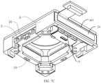
- a function of the outer magnet yoke 24 is to increase the driving force of the first driving mechanism 101, in order to improve the anti-shake effect of the camera structure provided in the embodiments of this application along the Rx axis and the Ry axis.
- the flexible circuit 2302 can form a planar spring structure to enable relative movement of the first sub-circuit board 2301 and the second sub-circuit board 2303.
- the second ball 11 can only rotate around the Z axis, so that when the gimbal carrier is under stress, the gimbal carrier can only rotate around the Z axis, thereby improving the accuracy of anti-shake along the Rz axis direction.
- an end of the second curved baffle 1002 can be provided with a rotation limit portion 1003 to limit the rotation of the gimbal carrier 10 relative to the inner gimbal support 5 along the Rz axis direction.
- the gimbal carrier 10 is clamped between the rolling supporting bracket 18 and the inner gimbal support 5 to limit the axial movement of the camera module 103 along the Z axis driven by the inner gimbal support 5, thereby improving the accuracy of the camera structure.
- a groove or through hole can be provided on the bottom surface of the gimbal carrier 10 that is attached to the rolling supporting bracket 18, and the second ball 19 can be clamped in the groove or the through hole to reduce the friction between the rolling supporting bracket 18 and the gimbal carrier 10, thereby improving the sensitivity of the second driving mechanism 102 to drive the gimbal carrier 10.
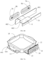
- the rolling supporting bracket 18 is an integrated structure, which specifically includes: a buckle structure 1801 configured to buckle with the inner gimbal support 5, a platform 1803 configured to support the second ball 19, and an installation plate 1805 configured to fix the first magnet yoke 22.
- the installation plate 1805 is provided with a third through hole to ensure that the buckle structure on the inner gimbal support 5 passes through the third through hole and is fixedly connected to the installation plate 1805 and the first magnet yoke 22.
- the first magnet yoke 22 can be fixed to the inner gimbal support 5 by clamping between the inner gimbal support 5 and the installation plate 1805, and the installation plate 1805 is provided with a spacing portion 1808 protruding towards the direction away from the gimbal carrier 10.
- the spacing portion 1808 separates the installation plate 1805 into two parts, so that when the first magnet group 21 is installed on one side of the installation plate 1805 facing away from the gimbal carrier 10, by separating the magnets of the first magnet group 21 through the spacing portion 1808 and limiting the magnets in the first magnet group 21, the fixed strength of the magnets in the first magnet group 21 can be improved.
- the camera structure can drive the camera module to rotate in the Rx direction, the Ry direction, and the Rz direction.
- the camera structure can also be combined with corresponding algorithm processing to achieve translation shake along the X axis and the Y axis.
- the occupied space of the circuit board is reduced, the overall volume of the camera structure is reduced, and more space is allowed for layout of other devices, such as increasing battery size and capacity to improve the battery life of a mobile phone, and indirectly improving the use experience of a consumer;
- a gimbal carrier structure and a driving structure thereof that can rotate in the Rz direction are disposed in the middle of the camera structure; and movement of the gimbal carrier structure and the driving structure thereof is independent of the movement along Rx and Ry, which can effectively reduce a crosstalk impact of three-axis synchronous drive;
- the gimbal carrier 10 is provided with the second driving coil group 15 and the driving element, which can be led out through the first circuit board 23 to connect to an external circuit.
- the first driving coil group 7 and the first position feedback element group 8 are disposed on a side of the camera structure and fixed on the outer gimbal support 9, which can be directly led out to connect to the external circuit.
- a clamping portion supporting structure with double-sided clamping of the first ball 4 can reduce the impact of multi degree of freedom vibration, thereby reducing changes in camera external parameters and providing strong support for multi camera fusion algorithms.
- the electronic device in the embodiments of this application may be a mobile electronic device or may be a non-mobile electronic device.
- the mobile electronic device may be a mobile phone, a tablet computer, a notebook computer, a palm computer, an in-vehicle electronic device, a wearable device, an ultra-mobile personal computer (UMPC), a netbook, or a personal digital assistant (PDA), and the non-mobile electronic device may be a personal computer (PC), a television (TV), a teller machine, or an automated machine, which are not specifically limited in the embodiments of this application.
- PC personal computer
- TV television
- teller machine teller machine
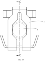
- the electronic device provided in embodiments of this application includes any camera structure shown in FIG. 1 to FIG. 8B , and has the same beneficial effect as any camera structure shown in FIG. 1 to FIG. 8B . To avoid repetition, it will not be repeated here.
Landscapes
- Engineering & Computer Science (AREA)
- Multimedia (AREA)
- Signal Processing (AREA)
- Physics & Mathematics (AREA)
- General Physics & Mathematics (AREA)
- Accessories Of Cameras (AREA)
- Studio Devices (AREA)
- Adjustment Of Camera Lenses (AREA)
Claims (15)
- Eine Kamerastruktur, die Folgendes beinhaltet: eine Gelenkwelle (2), eine äußere Kardanlagerung (9), eine in der äußeren Kardanlagerung (9) aufgenommene innere Kardanlagerung (5), einen Kardanträger (10), einen ersten Antriebsmechanismus (101), einen zweiten Antriebsmechanismus (102) und ein Kameramodul (103); wobei das Kameramodul (103) mit der äußeren Kardanlagerung (9) bewegbar verbunden ist und das Kameramodul (103) mit dem Kardanträger (10) fest verbunden ist;zwei lagernde Abschnitte (25) der Gelenkwelle (2), die axial entlang einer ersten Achse verteilt sind, und wobei zwei lagernde Abschnitte (25) der Gelenkwelle (2), die axial entlang einer zweiten Achse verteilt sind, mit der inneren Kardanlagerung (5) gelenkig verbunden sind, wobei sich die erste Achse mit der zweiten Achse schneidet;der erste Antriebsmechanismus (101) mit der äußeren Kardanlagerung (9) und der inneren Kardanlagerung (5) verbunden ist, um die innere Kardanlagerung (5) anzutreiben, sodass sie relativ zu der äußeren Kardanlagerung (9) entlang der ersten Achse und/oder der zweiten Achse rotiert;der Kardanträger (10) mit einem unteren Abschnitt der inneren Kardanlagerung (5) verschiebbar verbunden ist; und dadurch gekennzeichnet, dassder zweite Antriebsmechanismus (102) mit der inneren Kardanlagerung (5) und dem Kardanträger (10) verbunden ist, um den Kardanträger (10) anzutreiben, sodass er relativ zu der inneren Kardanlagerung (5) entlang einer dritten Achse rotiert, wobei die dritte Achse zu der ersten Achse und der zweiten Achse senkrecht ist.
- Kamerastruktur gemäß Anspruch 1, wobei es einen ersten Aufnahmeraum zwischen einer ersten inneren Seitenwand der äußeren Kardanlagerung (9) und einer ersten äußeren Seitenwand der inneren Kardanlagerung (5) gibt und der erste Antriebsmechanismus (101) und der zweite Antriebsmechanismus (102) in dem ersten Aufnahmeraum angeordnet sind.
- Kamerastruktur gemäß Anspruch 2, wobei der erste Antriebsmechanismus (101) Folgendes beinhaltet: ein erstes Magnetjoch (22), eine erste Antriebsspulengruppe (7) und eine erste Magnetgruppe (21); wobeidie erste Antriebsspulengruppe (7) an der äußeren Kardanlagerung (9) befestigt ist, das erste Magnetjoch (22) an der ersten äußeren Seitenwand der inneren Kardanlagerung (5) befestigt ist, die erste Magnetgruppe (21) an dem ersten Magnetjoch (22) befestigt ist und die erste Magnetgruppe (21) mit der ersten Antriebsspulengruppe (7) übereinstimmt; undmindestens zwei Spulen der ersten Antriebsspulengruppe (7) mit einem Intervall entlang einer ersten Richtung angeordnet sind, wobei die erste Richtung zu der dritten Achse senkrecht ist, wobei die erste Antriebsspulengruppe (7) auf zwei entgegengesetzten Seiten einer Symmetrieachse der inneren Kardanlagerung (5) verteilt ist und wobei die Symmetrieachse in einer gleichen Richtung wie eine Richtung von der ersten äußeren Seitenwand der inneren Kardanlagerung (5) zu der ersten inneren Seitenwand der äußeren Kardanlagerung (9) verläuft; wobei in einem Fall, dass die erste Antriebsspulengruppe (7) mit Strom erregt wird, eine Wechselwirkungskraft zwischen der ersten Antriebsspulengruppe (7) und der ersten Magnetgruppe (21) generiert wird, und wobei die erste Magnetgruppe (21) dazu konfiguriert ist, die innere Kardanlagerung (5) basierend auf der Wechselwirkungskraft anzutreiben, sodass sie relativ zu der äußeren Kardanlagerung (9) entlang der ersten Achse und/oder entlang der zweiten Achse rotiert.
- Kamerastruktur gemäß Anspruch 3, die ferner Folgendes beinhaltet:eine erste Positionsrückmeldungselementgruppe (8A, 8B), die dazu konfiguriert ist,einen Rotationsbetrag der inneren Kardanlagerung (5) relativ zu der äußeren Kardanlagerung (9) entlang der ersten Achse oder der zweiten Achse zu detektieren,wobei die erste Positionsrückmeldungselementgruppe (8A, 8B) in einem Magnetfeldbereich der ersten Magnetgruppe (21) und der ersten Antriebsspulengruppe (7) angeordnet ist.
- Kamerastruktur gemäß Anspruch 3, wobei der erste Antriebsmechanismus (101) ferner Folgendes beinhaltet: ein äußeres Magnetjoch (24); wobei
das äußere Magnetjoch (24) an der äußeren Kardanlagerung (9) befestigt ist und dazu konfiguriert ist, einen Magnetkreis mit der ersten Magnetgruppe (21) zu bilden. - Kamerastruktur gemäß Anspruch 2, wobei der zweite Antriebsmechanismus (102) Folgendes beinhaltet: ein zweites Magnetjoch (22), eine zweite Antriebsspulengruppe (15) und eine zweite Magnetgruppe (17); wobeidie zweite Antriebsspulengruppe (15) an dem Kardanträger (10) befestigt ist, das zweite Magnetjoch (22) an der ersten äußeren Seitenwand der inneren Kardanlagerung (5) befestigt ist, die zweite Magnetgruppe (17) an dem zweiten Magnetjoch (22) befestigt ist und die zweite Magnetgruppe (17) mit der zweiten Antriebsspulengruppe (15) übereinstimmt; undmindestens zwei Spulen der zweiten Antriebsspulengruppe (15) mit einem Intervall entlang einer ersten Richtung angeordnet sind, wobei die erste Richtung zu der dritten Achse senkrecht ist, wobei die zweite Antriebsspulengruppe (15) auf zwei entgegengesetzten Seiten einer Symmetrieachse des Kardanträgers (10) verteilt ist und wobei die Symmetrieachse in einer gleichen Richtung wie eine Richtung von der ersten äußeren Seitenwand der inneren Kardanlagerung (5) zu der ersten inneren Seitenwand der äußeren Kardanlagerung (9) verläuft; wobeiin einem Fall, dass die zweite Antriebsspulengruppe (15) mit Strom erregt wird, eine Wechselwirkungskraft zwischen der zweiten Antriebsspulengruppe (15) und der zweiten Magnetgruppe (17) generiert wird, und wobei die zweite Magnetgruppe (17) dazu konfiguriert ist, den Kardanträger (10) basierend auf der Wechselwirkungskraft anzutreiben, sodass er relativ zu der inneren Kardanlagerung (5) entlang der dritten Achse rotiert.
- Kamerastruktur gemäß Anspruch 6, die ferner Folgendes beinhaltet:
eine zweite Positionsrückmeldungselementgruppe (16), die dazu konfiguriert ist, einen Rotationsbetrag des Kardanträgers (10) relativ zu der inneren Kardanlagerung (5) entlang der dritten Achse zu detektieren, wobei die zweite Positionsrückmeldungselementgruppe (16) in einem Magnetfeldbereich der zweiten Magnetgruppe (17) und der zweiten Antriebsspulengruppe (15) angeordnet ist. - Kamerastruktur gemäß Anspruch 6, wobei der erste Antriebsmechanismus (101) ferner Folgendes beinhaltet: ein inneres Magnetjoch; wobei
das innere Magnetjoch an dem Kardanträger (10) befestigt ist und dazu konfiguriert ist, einen Magnetkreis mit der zweiten Magnetgruppe (17) zu bilden. - Kamerastruktur gemäß Anspruch 1, wobei jeder von den lagernden Abschnitten (25) mit einem ersten Durchgangsloch (251) versehen ist und eine axiale Richtung des ersten Durchgangslochs (251) senkrecht zu der dritten Achse ist; unddie Kamerastruktur ferner Folgendes beinhaltet: eine Adapterstruktur, wobei die Adapterstruktur einen Klemmabschnitt (3) und eine erste Kugel (4) beinhaltet; wobei die erste Kugel (4) innerhalb des ersten Durchgangslochs (251) angeordnet ist und zwischen zwei Seitenwänden des Klemmabschnitts (3) eingeklemmt ist; undder Klemmabschnitt (3) dazu konfiguriert ist, mit der äußeren Kardanlagerung (9) oder der inneren Kardanlagerung (5) fest verbunden zu werden.
- Kamerastruktur gemäß Anspruch 9, wobei die Adapterstruktur ferner Folgendes beinhaltet: eine Führungsplatte (302), wobei die Führungsplatte (302) mit einer ersten Seitenwand des Klemmabschnitts (3) fest verbunden ist und sich zu einer Richtung einer zweiten Seitenwand des Klemmabschnitts (3) erstreckt, und wobei die erste Seitenwand des Klemmabschnitts (3) und die zweite Seitenwand des Klemmabschnitts (3) zwei entgegensetzte Seitenwände des Klemmabschnitts (3) sind; und/oder die Adapterstruktur ferner Folgendes beinhaltet: eine Beschränkungsplatte (304), wobei die Beschränkungsplatte (304) an einem Ende des Klemmabschnitts (3) befestigt ist, das von der Gelenkwelle (2) entfernt ist, um einen Rotationswinkel des lagernden Abschnitts (25) zu beschränken, sodass er in einem Fall, dass der lagernde Abschnitt (25) relativ zu dem Klemmabschnitt (3) rotiert wird, weniger als ein voreingestellter Winkel ist.
- Kamerastruktur gemäß Anspruch 9 oder 10, wobei die äußere Kardanlagerung (9) und die innere Kardanlagerung (5) mit Klemmnuten (501, 901) versehen sind, die mit dem Klemmabschnitt (3) übereinstimmen, und wobei der Klemmabschnitt (3) in den Klemmnuten (501, 901) eingeklemmt ist, um den lagernden Abschnitt (25) mit der äußeren Kardanlagerung (9) oder der inneren Kardanlagerung (5) gelenkig zu verbinden.
- Kamerastruktur gemäß Anspruch 1, wobei das Kameramodul (103) eine Kamerakomponente (20) und eine erste Leiterplatte (23) beinhaltet; wobei die Kamerakomponente (20) an dem Kardanträger (10) befestigt ist; und die erste Leiterplatte (23) auf einer Seite der Kamerakomponente (20) befestigt ist, die von dem Kardanträger (10) entfernt ist, und die erste Leiterplatte (23) mit der äußeren Kardanlagerung (9) bewegbar verbunden ist.
- Kamerastruktur gemäß Anspruch 12, wobei die erste Leiterplatte (23) Folgendes beinhaltet: eine erste Teilleiterplatte (2301), eine zweite Teilleiterplatte (2303) und eine flexible Schaltung (2302); wobeidie zweite Teilleiterplatte (2303) die erste Teilleiterplatte (2301) umgibt und die erste Teilleiterplatte (2301) und die zweite Teilleiterplatte (2303) in einer gleichen Ebene liegen; unddie erste Teilleiterplatte (2301) mit der zweiten Teilleiterplatte (2303) über die flexible Schaltung (2302) bewegbar verbunden ist.
- Kamerastruktur gemäß Anspruch 1, wobei mindestens zwei erste gekrümmte Leitbleche (504) auf dem unteren Abschnitt der inneren Kardanlagerung (5) angeordnet sind und ein Ring, an dem die mindestens zwei ersten Leitbleche (504) liegen, koaxial mit der dritten Achse ist; undmindestens zwei zweite gekrümmte Leitbleche (1002), die sich in einer Eins-zu-Eins-Entsprechung mit den mindestens zwei ersten gekrümmten Leitblechen (504) befinden, auf dem Kardanträger (10) angeordnet sind, und eine erste gekrümmte Leiterplatte (504) und eine zweite gekrümmte Leiterplatte (1002) eine Gruppe gekrümmter Leiterplatten bilden; unddie Kamerastruktur ferner Folgendes beinhaltet: eine zweite Kugel (11), wobei eine zweite Kugel (11) in einer Gruppe gekrümmter Leiterplatten eingeklemmt ist;wobei die Kamerastruktur ferner Folgendes beinhaltet: eine rollende lagernde Halterung (18); wobeidie rollende lagernde Halterung (18) an der inneren Kardanlagerung (5) befestigt ist und an einer Seite des Kardanträgers (10) anliegt, die von der inneren Kardanlagerung (5) weg gerichtet ist, um die Bewegung des Kardanträgers (10) entlang einer Richtung der dritten Achse zu beschränken.
- Eine elektronische Vorrichtung, die die Kamerastruktur gemäß einem der Ansprüche 1 bis 14 beinhaltet.
Applications Claiming Priority (2)
| Application Number | Priority Date | Filing Date | Title |
|---|---|---|---|
| CN202110417591.2A CN112954185B (zh) | 2021-04-19 | 2021-04-19 | 摄像头结构及电子设备 |
| PCT/CN2022/086345 WO2022222791A1 (zh) | 2021-04-19 | 2022-04-12 | 摄像头结构及电子设备 |
Publications (3)
| Publication Number | Publication Date |
|---|---|
| EP4307653A1 EP4307653A1 (de) | 2024-01-17 |
| EP4307653A4 EP4307653A4 (de) | 2024-10-09 |
| EP4307653B1 true EP4307653B1 (de) | 2025-07-09 |
Family
ID=76232983
Family Applications (1)
| Application Number | Title | Priority Date | Filing Date |
|---|---|---|---|
| EP22790900.9A Active EP4307653B1 (de) | 2021-04-19 | 2022-04-12 | Kamerastruktur und elektronische vorrichtung |
Country Status (6)
| Country | Link |
|---|---|
| US (1) | US12477225B2 (de) |
| EP (1) | EP4307653B1 (de) |
| JP (1) | JP7651009B2 (de) |
| CN (1) | CN112954185B (de) |
| ES (1) | ES3037691T3 (de) |
| WO (1) | WO2022222791A1 (de) |
Families Citing this family (5)
| Publication number | Priority date | Publication date | Assignee | Title |
|---|---|---|---|---|
| CN113286062B (zh) * | 2021-04-19 | 2023-07-07 | 维沃移动通信有限公司 | 摄像头结构和电子设备 |
| CN112954185B (zh) | 2021-04-19 | 2023-04-07 | 维沃移动通信有限公司 | 摄像头结构及电子设备 |
| CN114125217B (zh) * | 2021-11-04 | 2024-09-24 | 维沃移动通信有限公司 | 摄像头模组及电子设备 |
| CN114401361B (zh) * | 2021-12-28 | 2024-06-28 | 维沃移动通信有限公司 | 摄像头结构及电子设备 |
| WO2025166493A1 (zh) * | 2024-02-05 | 2025-08-14 | 瑞声光电科技(常州)有限公司 | 一种防抖机构以及摄像模组 |
Family Cites Families (23)
| Publication number | Priority date | Publication date | Assignee | Title |
|---|---|---|---|---|
| JP2013246413A (ja) * | 2012-05-29 | 2013-12-09 | Sony Corp | 像ぶれ補正装置及び撮像装置 |
| JP2015121755A (ja) * | 2013-12-25 | 2015-07-02 | キヤノン株式会社 | 像振れ補正装置、レンズ装置、および、撮像装置 |
| JP6311434B2 (ja) * | 2014-04-25 | 2018-04-18 | ミツミ電機株式会社 | アクチュエーター、カメラモジュール、及びカメラ付き携帯端末 |
| JP6460745B2 (ja) * | 2014-11-21 | 2019-01-30 | 日本電産サンキョー株式会社 | 振れ補正機能付き光学ユニット |
| KR20170050924A (ko) * | 2015-11-02 | 2017-05-11 | 삼성전자주식회사 | 3축 조정 소형 짐벌 |
| KR20170065235A (ko) * | 2015-12-03 | 2017-06-13 | 삼성전자주식회사 | 소형 카메라 짐벌 |
| US20170302852A1 (en) * | 2016-04-13 | 2017-10-19 | Jason Tze Wah Lam | Three Axis Gimbals Stabilized Action Camera Lens Unit |
| JP6779104B2 (ja) * | 2016-11-10 | 2020-11-04 | 日本電産サンキョー株式会社 | 振れ補正機能付き光学ユニット |
| CN107315302B (zh) * | 2017-08-25 | 2020-03-31 | 高瞻创新科技有限公司 | 一种具有多自由度的电路板及防抖微型致动器 |
| CN107340667B (zh) * | 2017-08-25 | 2020-04-21 | 高瞻创新科技有限公司 | 一种整合相机模组的防抖微型云台 |
| KR102799830B1 (ko) | 2018-09-05 | 2025-04-28 | 엘지이노텍 주식회사 | 카메라 모듈 |
| JP7290457B2 (ja) * | 2019-04-24 | 2023-06-13 | ニデックインスツルメンツ株式会社 | 振れ補正機能付き光学ユニット |
| JP7344679B2 (ja) * | 2019-06-14 | 2023-09-14 | ニデックインスツルメンツ株式会社 | 振れ補正機能付き光学ユニット |
| JP7320403B2 (ja) * | 2019-08-09 | 2023-08-03 | ニデックインスツルメンツ株式会社 | 振れ補正機能付き光学ユニット |
| JP7330808B2 (ja) * | 2019-08-09 | 2023-08-22 | ニデックインスツルメンツ株式会社 | 振れ補正機能付き光学ユニット |
| CN113669563B (zh) * | 2020-04-30 | 2025-02-14 | 新思考电机有限公司 | 两轴倾斜装置、照相装置以及电子设备 |
| CN111586269B (zh) * | 2020-05-07 | 2022-02-18 | Oppo广东移动通信有限公司 | 成像装置及电子设备 |
| CN111917966B (zh) * | 2020-08-26 | 2025-01-28 | 河南皓泽电子股份有限公司昆山分公司 | 摄像模组及其电子设备 |
| JP7467286B2 (ja) * | 2020-08-31 | 2024-04-15 | ニデックインスツルメンツ株式会社 | 振れ補正機能付き光学ユニット |
| CN112198735B (zh) | 2020-12-01 | 2021-02-19 | 常州市瑞泰光电有限公司 | 一种镜头驱动装置 |
| CN112822363B (zh) * | 2020-12-31 | 2022-10-14 | 维沃移动通信有限公司 | 摄像头模组及电子设备 |
| CN113286062B (zh) * | 2021-04-19 | 2023-07-07 | 维沃移动通信有限公司 | 摄像头结构和电子设备 |
| CN112954185B (zh) * | 2021-04-19 | 2023-04-07 | 维沃移动通信有限公司 | 摄像头结构及电子设备 |
-
2021
- 2021-04-19 CN CN202110417591.2A patent/CN112954185B/zh active Active
-
2022
- 2022-04-12 ES ES22790900T patent/ES3037691T3/es active Active
- 2022-04-12 EP EP22790900.9A patent/EP4307653B1/de active Active
- 2022-04-12 JP JP2023562591A patent/JP7651009B2/ja active Active
- 2022-04-12 WO PCT/CN2022/086345 patent/WO2022222791A1/zh not_active Ceased
-
2023
- 2023-10-18 US US18/381,421 patent/US12477225B2/en active Active
Also Published As
| Publication number | Publication date |
|---|---|
| US20240048846A1 (en) | 2024-02-08 |
| CN112954185B (zh) | 2023-04-07 |
| WO2022222791A1 (zh) | 2022-10-27 |
| JP2024514144A (ja) | 2024-03-28 |
| US12477225B2 (en) | 2025-11-18 |
| ES3037691T3 (en) | 2025-10-06 |
| JP7651009B2 (ja) | 2025-03-25 |
| EP4307653A4 (de) | 2024-10-09 |
| EP4307653A1 (de) | 2024-01-17 |
| CN112954185A (zh) | 2021-06-11 |
Similar Documents
| Publication | Publication Date | Title |
|---|---|---|
| EP4307653B1 (de) | Kamerastruktur und elektronische vorrichtung | |
| US12455498B2 (en) | Photographing apparatus, electronic device, and control method of photographing apparatus | |
| US11095819B2 (en) | Camera module having electromagnetic driving assembly | |
| CN112954186B (zh) | 摄像头结构及电子设备 | |
| CN107277307B (zh) | 摄像模块 | |
| CN113286062B (zh) | 摄像头结构和电子设备 | |
| US12013589B2 (en) | Lens driving device, and camera module and optical device comprising same | |
| EP4016984A1 (de) | Optisches bildstabilisierungsmodul und elektronische vorrichtung | |
| CN111953881A (zh) | 镜头模组 | |
| WO2016006780A1 (ko) | 카메라 렌즈 모듈 | |
| EP4171007B1 (de) | Kameramodul und elektronische vorrichtung | |
| CN118612538A (zh) | 驱动马达、摄像模组以及电子设备 | |
| KR20210092572A (ko) | 카메라 모듈 | |
| CN113099086B (zh) | 摄像头装置和电子设备 | |
| JP2025124758A (ja) | カメラモジュール | |
| CN119071616B (zh) | 摄像头模组及电子设备 | |
| CN120614527A (zh) | 图像传感器模组、摄像模组和电子设备 | |
| WO2026001586A1 (zh) | 一种折叠电路板结构、防抖云台、摄像装置及电子设备 | |
| CN120835194A (zh) | 马达、摄像模组及电子设备 | |
| KR20240169949A (ko) | 카메라 장치 및 광학 기기 |
Legal Events
| Date | Code | Title | Description |
|---|---|---|---|
| STAA | Information on the status of an ep patent application or granted ep patent |
Free format text: STATUS: THE INTERNATIONAL PUBLICATION HAS BEEN MADE |
|
| PUAI | Public reference made under article 153(3) epc to a published international application that has entered the european phase |
Free format text: ORIGINAL CODE: 0009012 |
|
| STAA | Information on the status of an ep patent application or granted ep patent |
Free format text: STATUS: REQUEST FOR EXAMINATION WAS MADE |
|
| 17P | Request for examination filed |
Effective date: 20231010 |
|
| AK | Designated contracting states |
Kind code of ref document: A1 Designated state(s): AL AT BE BG CH CY CZ DE DK EE ES FI FR GB GR HR HU IE IS IT LI LT LU LV MC MK MT NL NO PL PT RO RS SE SI SK SM TR |
|
| DAV | Request for validation of the european patent (deleted) | ||
| DAX | Request for extension of the european patent (deleted) | ||
| REG | Reference to a national code |
Ref country code: DE Ref legal event code: R079 Ipc: G03B0017560000 Ref document number: 602022017432 Country of ref document: DE Free format text: PREVIOUS MAIN CLASS: H04N0005225000 |
|
| A4 | Supplementary search report drawn up and despatched |
Effective date: 20240910 |
|
| RIC1 | Information provided on ipc code assigned before grant |
Ipc: H04N 23/57 20230101ALI20240904BHEP Ipc: G03B 17/56 20210101AFI20240904BHEP |
|
| GRAP | Despatch of communication of intention to grant a patent |
Free format text: ORIGINAL CODE: EPIDOSNIGR1 |
|
| STAA | Information on the status of an ep patent application or granted ep patent |
Free format text: STATUS: GRANT OF PATENT IS INTENDED |
|
| INTG | Intention to grant announced |
Effective date: 20250414 |
|
| GRAS | Grant fee paid |
Free format text: ORIGINAL CODE: EPIDOSNIGR3 |
|
| GRAA | (expected) grant |
Free format text: ORIGINAL CODE: 0009210 |
|
| STAA | Information on the status of an ep patent application or granted ep patent |
Free format text: STATUS: THE PATENT HAS BEEN GRANTED |
|
| AK | Designated contracting states |
Kind code of ref document: B1 Designated state(s): AL AT BE BG CH CY CZ DE DK EE ES FI FR GB GR HR HU IE IS IT LI LT LU LV MC MK MT NL NO PL PT RO RS SE SI SK SM TR |
|
| REG | Reference to a national code |
Ref country code: GB Ref legal event code: FG4D |
|
| REG | Reference to a national code |
Ref country code: CH Ref legal event code: EP |
|
| REG | Reference to a national code |
Ref country code: IE Ref legal event code: FG4D |
|
| REG | Reference to a national code |
Ref country code: DE Ref legal event code: R096 Ref document number: 602022017432 Country of ref document: DE |
|
| REG | Reference to a national code |
Ref country code: NL Ref legal event code: FP |
|
| REG | Reference to a national code |
Ref country code: ES Ref legal event code: FG2A Ref document number: 3037691 Country of ref document: ES Kind code of ref document: T3 Effective date: 20251006 |
|
| PG25 | Lapsed in a contracting state [announced via postgrant information from national office to epo] |
Ref country code: PT Free format text: LAPSE BECAUSE OF FAILURE TO SUBMIT A TRANSLATION OF THE DESCRIPTION OR TO PAY THE FEE WITHIN THE PRESCRIBED TIME-LIMIT Effective date: 20251110 |
|
| REG | Reference to a national code |
Ref country code: AT Ref legal event code: MK05 Ref document number: 1812367 Country of ref document: AT Kind code of ref document: T Effective date: 20250709 |
|
| PG25 | Lapsed in a contracting state [announced via postgrant information from national office to epo] |
Ref country code: IS Free format text: LAPSE BECAUSE OF FAILURE TO SUBMIT A TRANSLATION OF THE DESCRIPTION OR TO PAY THE FEE WITHIN THE PRESCRIBED TIME-LIMIT Effective date: 20251109 |
|
| PG25 | Lapsed in a contracting state [announced via postgrant information from national office to epo] |
Ref country code: NO Free format text: LAPSE BECAUSE OF FAILURE TO SUBMIT A TRANSLATION OF THE DESCRIPTION OR TO PAY THE FEE WITHIN THE PRESCRIBED TIME-LIMIT Effective date: 20251009 |
|
| REG | Reference to a national code |
Ref country code: LT Ref legal event code: MG9D |
|
| PG25 | Lapsed in a contracting state [announced via postgrant information from national office to epo] |
Ref country code: AT Free format text: LAPSE BECAUSE OF FAILURE TO SUBMIT A TRANSLATION OF THE DESCRIPTION OR TO PAY THE FEE WITHIN THE PRESCRIBED TIME-LIMIT Effective date: 20250709 |
|
| PG25 | Lapsed in a contracting state [announced via postgrant information from national office to epo] |
Ref country code: FI Free format text: LAPSE BECAUSE OF FAILURE TO SUBMIT A TRANSLATION OF THE DESCRIPTION OR TO PAY THE FEE WITHIN THE PRESCRIBED TIME-LIMIT Effective date: 20250709 |
|
| PG25 | Lapsed in a contracting state [announced via postgrant information from national office to epo] |
Ref country code: HR Free format text: LAPSE BECAUSE OF FAILURE TO SUBMIT A TRANSLATION OF THE DESCRIPTION OR TO PAY THE FEE WITHIN THE PRESCRIBED TIME-LIMIT Effective date: 20250709 |
|
| PG25 | Lapsed in a contracting state [announced via postgrant information from national office to epo] |
Ref country code: GR Free format text: LAPSE BECAUSE OF FAILURE TO SUBMIT A TRANSLATION OF THE DESCRIPTION OR TO PAY THE FEE WITHIN THE PRESCRIBED TIME-LIMIT Effective date: 20251010 |
|
| PG25 | Lapsed in a contracting state [announced via postgrant information from national office to epo] |
Ref country code: SE Free format text: LAPSE BECAUSE OF FAILURE TO SUBMIT A TRANSLATION OF THE DESCRIPTION OR TO PAY THE FEE WITHIN THE PRESCRIBED TIME-LIMIT Effective date: 20250709 |
|
| PG25 | Lapsed in a contracting state [announced via postgrant information from national office to epo] |
Ref country code: LV Free format text: LAPSE BECAUSE OF FAILURE TO SUBMIT A TRANSLATION OF THE DESCRIPTION OR TO PAY THE FEE WITHIN THE PRESCRIBED TIME-LIMIT Effective date: 20250709 |
|
| PG25 | Lapsed in a contracting state [announced via postgrant information from national office to epo] |
Ref country code: BG Free format text: LAPSE BECAUSE OF FAILURE TO SUBMIT A TRANSLATION OF THE DESCRIPTION OR TO PAY THE FEE WITHIN THE PRESCRIBED TIME-LIMIT Effective date: 20250709 Ref country code: PL Free format text: LAPSE BECAUSE OF FAILURE TO SUBMIT A TRANSLATION OF THE DESCRIPTION OR TO PAY THE FEE WITHIN THE PRESCRIBED TIME-LIMIT Effective date: 20250709 |
|
| PG25 | Lapsed in a contracting state [announced via postgrant information from national office to epo] |
Ref country code: RS Free format text: LAPSE BECAUSE OF FAILURE TO SUBMIT A TRANSLATION OF THE DESCRIPTION OR TO PAY THE FEE WITHIN THE PRESCRIBED TIME-LIMIT Effective date: 20251009 |
|
| PG25 | Lapsed in a contracting state [announced via postgrant information from national office to epo] |
Ref country code: SM Free format text: LAPSE BECAUSE OF FAILURE TO SUBMIT A TRANSLATION OF THE DESCRIPTION OR TO PAY THE FEE WITHIN THE PRESCRIBED TIME-LIMIT Effective date: 20250709 |
|
| PGFP | Annual fee paid to national office [announced via postgrant information from national office to epo] |
Ref country code: GB Payment date: 20260303 Year of fee payment: 5 |
|
| PG25 | Lapsed in a contracting state [announced via postgrant information from national office to epo] |
Ref country code: DK Free format text: LAPSE BECAUSE OF FAILURE TO SUBMIT A TRANSLATION OF THE DESCRIPTION OR TO PAY THE FEE WITHIN THE PRESCRIBED TIME-LIMIT Effective date: 20250709 |
|
| PGFP | Annual fee paid to national office [announced via postgrant information from national office to epo] |
Ref country code: IT Payment date: 20260320 Year of fee payment: 5 |
|
| PGFP | Annual fee paid to national office [announced via postgrant information from national office to epo] |
Ref country code: NL Payment date: 20260317 Year of fee payment: 5 |
|
| PGFP | Annual fee paid to national office [announced via postgrant information from national office to epo] |
Ref country code: FR Payment date: 20260309 Year of fee payment: 5 |
|
| PG25 | Lapsed in a contracting state [announced via postgrant information from national office to epo] |
Ref country code: CZ Free format text: LAPSE BECAUSE OF FAILURE TO SUBMIT A TRANSLATION OF THE DESCRIPTION OR TO PAY THE FEE WITHIN THE PRESCRIBED TIME-LIMIT Effective date: 20250709 |
|
| PG25 | Lapsed in a contracting state [announced via postgrant information from national office to epo] |
Ref country code: EE Free format text: LAPSE BECAUSE OF FAILURE TO SUBMIT A TRANSLATION OF THE DESCRIPTION OR TO PAY THE FEE WITHIN THE PRESCRIBED TIME-LIMIT Effective date: 20250709 Ref country code: SK Free format text: LAPSE BECAUSE OF FAILURE TO SUBMIT A TRANSLATION OF THE DESCRIPTION OR TO PAY THE FEE WITHIN THE PRESCRIBED TIME-LIMIT Effective date: 20250709 |