EP4308351B1 - Appareil de fraisage multi-profil et dispositif d'usinage - Google Patents
Appareil de fraisage multi-profil et dispositif d'usinage Download PDFInfo
- Publication number
- EP4308351B1 EP4308351B1 EP22714846.7A EP22714846A EP4308351B1 EP 4308351 B1 EP4308351 B1 EP 4308351B1 EP 22714846 A EP22714846 A EP 22714846A EP 4308351 B1 EP4308351 B1 EP 4308351B1
- Authority
- EP
- European Patent Office
- Prior art keywords
- milling
- milling device
- use position
- profile
- centrifugal
- Prior art date
- Legal status (The legal status is an assumption and is not a legal conclusion. Google has not performed a legal analysis and makes no representation as to the accuracy of the status listed.)
- Active
Links
Images

Classifications
-
- B—PERFORMING OPERATIONS; TRANSPORTING
- B27—WORKING OR PRESERVING WOOD OR SIMILAR MATERIAL; NAILING OR STAPLING MACHINES IN GENERAL
- B27D—WORKING VENEER OR PLYWOOD
- B27D5/00—Other working of veneer or plywood specially adapted to veneer or plywood
- B27D5/006—Trimming, chamfering or bevelling edgings, e.g. lists
-
- B—PERFORMING OPERATIONS; TRANSPORTING
- B27—WORKING OR PRESERVING WOOD OR SIMILAR MATERIAL; NAILING OR STAPLING MACHINES IN GENERAL
- B27G—ACCESSORY MACHINES OR APPARATUS FOR WORKING WOOD OR SIMILAR MATERIALS; TOOLS FOR WORKING WOOD OR SIMILAR MATERIALS; SAFETY DEVICES FOR WOOD WORKING MACHINES OR TOOLS
- B27G13/00—Cutter blocks; Other rotary cutting tools
- B27G13/005—Tools composed of two or more rotating discs
- B27G13/007—Tools composed of two or more rotating discs which are adjustable relatively to each other
-
- B—PERFORMING OPERATIONS; TRANSPORTING
- B23—MACHINE TOOLS; METAL-WORKING NOT OTHERWISE PROVIDED FOR
- B23C—MILLING
- B23C2210/00—Details of milling cutters
- B23C2210/02—Connections between the shanks and detachable cutting heads
-
- B—PERFORMING OPERATIONS; TRANSPORTING
- B23—MACHINE TOOLS; METAL-WORKING NOT OTHERWISE PROVIDED FOR
- B23C—MILLING
- B23C2210/00—Details of milling cutters
- B23C2210/24—Overall form of the milling cutter
- B23C2210/244—Milling cutters comprised of disc-shaped modules or multiple disc-like cutters
-
- B—PERFORMING OPERATIONS; TRANSPORTING
- B23—MACHINE TOOLS; METAL-WORKING NOT OTHERWISE PROVIDED FOR
- B23C—MILLING
- B23C2270/00—Details of milling machines, milling processes or milling tools not otherwise provided for
- B23C2270/04—Use of centrifugal force
Definitions
- the invention relates to a multi-profile milling device for machining workpieces and a machining device.
- the DE 19 915 672 A1 which forms the basis for the two-part version of independent claim 1, discloses a multi-profile milling device for machining workpiece edges.
- This multi-profile milling device comprises two milling devices, each of which has a milling tool with different machining profiles.
- a first milling device is arranged in a working position in order to machine the workpiece edge with a first machining profile.
- a second milling device can be moved axially to the first milling device between a rest position and a working position, whereby the machining profile of the second milling device superimposes the machining profile of the first milling device for the machining process.
- the adjusting movement of the second milling device takes place via a coupling fork which is controlled by a pneumatic cylinder.
- To lock the second milling device during the machining process it is positioned without play, in particular in the working position, by means of a hydraulic clamping device.
- Such a hydraulic clamping device has a complex structure and increases the costs of this multi-
- the invention is based on the object of proposing a multi-profile milling device which has a simplified structural design and enables flexible integration into a machining device.
- the invention is based on the object of proposing a machining device which has a high operational reliability in multi-profile milling.
- a multi-profile milling device is defined in claim 1.
- a machining device is defined in claim 13. Subclaims relate to specific embodiments.
- a multi-profile milling device for machining workpieces which are preferably made of wood, wood materials, plastic, composite material and/or the like, in particular for machining edges of the workpieces, with a first milling device which is provided in a working position and can be coupled to a drive shaft, and with at least one second milling device which is movable relative to the first milling device between a use position and a non-use position, wherein a locking device with at least one centrifugal force element is provided and the at least one centrifugal force element locks the at least one second milling device in the use position or the non-use position during a rotational movement of the milling devices.
- multi-profile milling device workpieces, in particular edges of workpieces, can be machined with different machining profiles, for example different radii or bevels.
- the second milling device being movable axially to the second milling device, whereby Machining process, a superposition of the different machining profiles is provided.
- the at least one centrifugal force element of the locking device forms a fixation of the second milling device in that the centrifugal force element, due to a centrifugal force generated during the rotational movement, locks the second milling device in the use position or the non-use position.
- the multi-profile milling device also enables multi-profile machining of a peripheral edge on the workpiece, for example the peripheral edge that borders a narrow side of a plate-shaped workpiece.
- a preferred embodiment of the multi-profile milling device can provide that the first milling device and the at least one second milling device are arranged coaxially to one another and the locking device is arranged to act between the milling devices.
- the coaxial arrangement of the two milling devices allows a simple structural design of the multi-profile milling device to be achieved, in which the second milling device is provided so that it can move axially relative to the first milling device. Since the locking device acts between the milling devices, a compact design can also be achieved.
- the at least one second milling device is axially displaceable and rotationally fixedly coupled to the first milling device.
- a torque transmitted to the first milling device can be transmitted to the second milling device and at the same time the axial displaceability of the second milling device between the use position and the non-use position can be enabled.
- the locking device has at least two centrifugal force elements, wherein at least a first centrifugal force element locks the second milling device in the use position and at least a second Centrifugal force element locks the second milling device in the non-use position.
- At least one centrifugal force element can be provided for locking the second milling device in the use position or in the non-use position, so that the second milling device is securely locked during the machining process.
- the at least two centrifugal force elements in the multi-profile milling device can be arranged spaced apart from one another in an axial direction.
- This axial spacing of the at least two centrifugal force elements allows for precise positioning of the second milling device in the use position and in the non-use position with a defined distance between the centrifugal force elements.
- a short adjustment path can also be formed between the use position and the non-use position.
- the multi-profile milling device can be provided with the at least two centrifugal force elements each being accommodated in a recess on the outer circumference of the first milling device and with at least one depression being formed on an inner circumference of the second milling device, which depression is positioned relative to the at least one first centrifugal force element in the use position of the second milling device and relative to the at least one second centrifugal force element in the non-use position of the second milling device.
- this also allows the locking device to be installed directly between the milling devices.
- the locking device can be protected between the milling devices so that reduced interference due to dirt, dust, sawdust or the like can be achieved.
- the at least one centrifugal force element is accommodated in a recess on the outer circumference of the first milling device and at least two recesses are formed on the inner circumference of the second milling device at an axial distance from one another, wherein in the use position of the second milling device a first recess is positioned relative to the centrifugal force element and in the non-use position a second recess is positioned relative to the centrifugal force element.
- This design of the locking device can achieve a reduction in the centrifugal force elements.
- the multi-profile milling device that at least one centrifugal force element is transferred into a locking position by the rotary movement of the milling devices, in which the at least one centrifugal force element is arranged partially in the recess on the outer circumference of the first milling device and partially in the at least one corresponding recess on the inner circumference of the second milling device.
- the at least one centrifugal force element makes it possible for the at least one centrifugal force element to securely lock the second milling device during the rotational movement of the milling devices and to release the at least one second milling device during a standstill for transfer between the use position or the non-use position.
- the at least one centrifugal force element is designed as a ball or as a cylindrical body, the radially outward-facing end face of which is rounded or conical.
- the corresponding recess can be designed as a bore with a minimally larger diameter than the spherical or cylindrical centrifugal force element.
- axial play of the spherical or cylindrical centrifugal force element can be minimized or eliminated.
- a further preferred embodiment of the multi-profile milling device can provide that the at least one recess on the inner circumference of the second milling device in the longitudinal section of the second milling device has an inclined surface arranged on the side of the use position and is preferably V-shaped.
- a particularly preferred embodiment of the multi-profile milling device can provide that the at least one first centrifugal force element in the locking position acts on the inclined surface of the at least one recess in such a way that an axial force component is formed which presses the second milling device in the use position against at least one stop defining the use position.
- This design allows a defined axial stop to be formed for the use position, so that the second milling device can be positioned without play during the machining process.
- the stop can be formed in conjunction with at least one stop element between the first and second milling devices.
- the at least one centrifugal force element is dimensioned in such a way that the axial force component generated by the centrifugal force is greater than the axial forces generated by the machining process.
- the at least one second centrifugal force element acts in the locking position on a further inclined surface of the recess arranged on the side of the non-use position in such a way that an axial force component presses the second milling device in the non-use position against at least one stop defining the non-use position.
- the at least one stop defining the use position and/or the non-use position can have at least one point-shaped or cam-shaped stop surface.
- the stop is formed by three point-shaped or cam-shaped stop surfaces.
- a defined stop plane can be formed, which enables precise positioning of the second milling device, in particular in the position of use.
- the at least one stop can be arranged between an outer circumference of the first milling device and an inner circumference of the second Milling device can be arranged in a concealed manner. In this way, the at least one stop can be protected against contamination.
- a further advantageous embodiment of the multi-profile milling device can provide that the at least one stop defining the use position is provided so as to be axially displaceable by an adjusting device.
- an axial position of the stop surfaces relative to one another can be changed, for example by means of an eccentric, whereby a precise axial positioning of the second milling device can be provided.
- a depth of the recess is designed in such a way that the at least one spherical or cylindrical centrifugal force element is arranged at least halfway in the recess in the locking position.
- a minimal axial play can be formed between the at least one spherical centrifugal force element and the recess, since the centrifugal force element remains in the recess with the largest diameter in the locking position. In this way, an axial movement of the centrifugal force element can be prevented in the locking position.
- a feeler roller can also be provided, which is mounted in a rotationally decoupled manner on the first milling device and/or the drive shaft.
- This sensing roller can be used to provide a guided movement of the multi-profile milling device to the workpiece during the machining process, which ensures a uniform and thus high-quality processing results can be achieved.
- a processing device for machining workpieces which are preferably made of wood, wood materials, plastic, composite material and/or the like, in particular for machining edges of the workpieces, having a workpiece support for receiving at least one workpiece, a multi-profile milling device for carrying out the machining process on the workpiece, a drive device for driving the multi-profile milling device and a conveyor device for bringing about a relative movement between the workpiece and the multi-profile milling device, wherein the multi-profile milling device is designed according to one of the previously described embodiments.
- the processing device with such a multi-profile milling device enables the processing of workpieces, in particular edges of workpieces, with different processing profiles.
- the processing profiles can have different radii or chamfers, for example. In this way, set-up times for changing tools for different processing profiles can be avoided and thus time- and cost-saving processing of the workpieces can be achieved.
- a preferred further development of the processing device can provide that an adjusting device is provided which controls an adjusting movement of the at least one second milling device between the use position or the non-use position.
- automation of multi-profile machining can be achieved by controlling the adjusting device, for example, by a control system, so that the axial adjusting movement of the second milling device depending on the machining profile to be generated.
- a sensor device can be provided which detects a setting position of the at least one second milling device.
- Such a sensor device enables the precise detection of the setting position of the second milling device, so that the machining process can be controlled based on the detection signal.
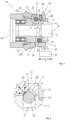
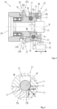
- FIG 1 shows a side view of an embodiment of a multi-profile milling device 10 according to the disclosure and Figure 2 a perspective partial exploded view of the multi-profile milling device 10 with a dismantled sensing roller 26.
- a multi-profile milling device 10 is intended for machining workpieces with different machining profiles or milling profiles.
- the multi-profile milling device 10 is intended for machining edges of the workpieces.
- the multi-profile milling device 10 is connected via a corresponding interface to a Figure 1 indicated processing device 20.
- the processing device 20 can be any machine tool for processing workpieces.
- the processing device 20 is designed as a wood processing device.
- the processing device 20 can be designed as a continuous machine or as a stationary machine tool.
- the workpieces are processed in a continuous process, with the workpieces being moved relative to the multi-profile milling device 10 by a transport device.
- the multi-profile milling device 10 can be arranged to be movable relative to the workpiece in an X, Y and/or Z direction by an adjusting device.
- a stationary machine tool the workpiece can be held stationary and the multi-profile milling device 10 can be movable relative to the workpiece by an adjusting device.
- the processing device can also be designed as a CNC-controlled processing device or a CNC-controlled machining center.
- the workpieces to be processed are in particular workpieces that are at least partially made of wood, wood materials, plastic, composite material or the like. These can be different workpieces, for example solid wood or chipboard, lightweight panels, Sandwich panels, skirting boards, profiles or the like.
- the workpieces are preferably plate-shaped workpieces.
- the present invention is not limited to the processing of such workpieces and materials.
- the multi-profile milling device 10 comprises a first milling device 11, a second milling device 12 and a feeler roller 26.
- the two milling devices 11, 12 are each formed by a base body which is arranged coaxially to one another and can be rotated about a common axis of rotation R.
- the milling devices 11, 12 each form a substantially rotationally symmetrical body.
- the first milling device 11 can be coupled to a drive shaft 13 in a rotationally fixed manner to transmit a torque, for example by means of a screw connection.
- the first milling device 11 and the drive shaft 13 can also be integrally formed.
- the drive shaft 13 can be coupled to a drive device of the processing device 20 by means of an interface (not shown in detail).
- the drive shaft 13 can also be a component of the processing device 20 and can be coupled to the first milling device 11 in a rotationally fixed manner via an interface.
- the second milling device 12 is provided coaxially to the first milling device 11 and is arranged with an inner circumference 14 on an outer circumference 16 of the first milling device 11.
- the outer circumference 16 of the first milling device 11 and the inner circumference 14 of the second milling device 12 are formed at least in sections parallel to the common axis of rotation R.
- the second milling device 12 is provided on the outer circumference 14 of the first milling device 11 so that it can be axially displaced relative to the first milling device 11.
- a torque introduced via the drive shaft 13 can be transmitted via the first milling device 11 to the second milling device 12 so that the two milling devices 11, 12 are in synchronism.
- the Synchronous operation can be achieved, for example, by means of a driver or a shaped profile.
- the second milling device 12 is both axially displaceable and rotationally fixedly coupled to the first milling device 11.
- a first milling tool 18 is provided on a front side of the first milling device 11, which forms a first machining profile 19 for machining the workpiece.
- the first machining profile 19 is designed as a defined milling radius or a defined milling chamfer for machining the workpiece edge.
- the first milling tool 18 can be detachably attached to the first milling device 11 by fastening means.
- the first milling tool 18 is arranged in a fixed working position and mills an edge of the workpiece onto the corresponding first machining profile 19 by means of a rotary movement about the axis of rotation R and a relative movement between the workpiece and the multi-profile milling device 10.
- a second milling tool 21 is provided, which forms a second machining profile 22 for machining the workpiece.
- the second machining profile 22 is designed as a milling radius or a milling chamfer that differs from the first machining profile 19.
- the second machining profile 22 of the second milling tool 21 can have a smaller milling radius than the first machining profile 19 of the first milling tool 18.
- the second milling tool 21 can be fastened to the second milling device 12 by fastening means.
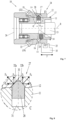
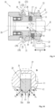
- FIGS 3 and 5 show sectional views of the multi-profile milling device 10, in which Figure 3 the second milling device 12 is provided in a use position 24 and in Figure 5 the first milling device 11 is provided in the working position. Due to the axial displacement the second milling device 12 relative to the first milling device 11, this is from the in Figure 3 shown use position 24 into the Figure 5 shown non-use position 23.
- the second milling tool 21 is arranged in a working position such that cutting elements of the second milling tool 21 of the second milling device 12 engage in spaces between cutting elements of the first milling tool 18 of the first milling device 11, so that the second machining profile 22 of the second milling tool 21 superimposes the first machining profile 19 of the first milling tool 18.
- the multi-profile milling device 10 is consequently set up such that the second machining profile 22 of the second milling tool 21 superimposes the first machining profile 19 of the first milling tool 18 in such a way that the workpiece is machined by the second machining profile 22 when the second milling device 12 is in the use position 24. This ensures that, although both milling tools 18, 21 machine a workpiece simultaneously, only the machining profile 22 of the second milling tool 21 is transferred to the workpiece.
- the multi-profile milling device 10 also has the sensing roller 26.
- the sensing roller 26 is mounted on the first milling device 11 in a rotationally decoupled manner, for example by one or more roller bearings.
- the sensing roller 26 can thus carry out the rolling movement on the workpiece surface independently of the rotational movement of the milling devices 11, 12.
- the sensing roller 26 can, for example, be mounted in a front-side bore in the first milling device 11.
- the first and second milling devices 11, 12 have the same base diameter. so that with each of the milling devices 11, 12 the machining process can be carried out in cooperation with the feeler roller 26.
- FIG 3 shows a locking device 27 which locks the second milling device 12 in the axial direction during the rotary movement of the milling devices 11, 12.
- the locking device 27 has several centrifugal force elements 28, 29 and is arranged to act between the two milling devices 11, 12 during the rotary movement.
- a first centrifugal force element 28 locks the second milling device 12 in the use position 24 ( Figure 3 ) and a second centrifugal force element 29 locks the second milling device 12 in the non-use position 23 ( Figure 5 ).
- the centrifugal force elements 28, 29 are arranged at a distance a from one another in an axial direction on the outer circumference 16 of the first milling device 11.
- the centrifugal force elements 28, 29 are thus provided on the outer circumference 16 in two axially spaced planes that run perpendicular to the axis of rotation R.
- the distance a can preferably be relatively small in order to form the shortest possible travel between the use position 24 and the non-use position 23.
- the centrifugal force elements 28, 29 can at least partially overlap in a radial plane within the distance a. It can be advantageous to use centrifugal force elements 28, 29 with the smallest possible diameter.
- centrifugal force elements 28, 29 can be used.
- the centrifugal force elements 28, 29 can also be made of a material with a high density, e.g. hard metal.
- the centrifugal force elements 28, 29 are preferably arranged on the first milling device 11 in such a way that an imbalance is prevented.
- centrifugal force elements 28, 29 can be provided in a common plane perpendicular to the axis of rotation R on the outer circumference 16 of the first milling device 11, even if only one centrifugal force element 28, 29 is described below.
- the centrifugal force elements 28, 29 are each accommodated in a recess 31 on the outer circumference 16 of the first milling device 11.
- the recesses 31 are designed in particular as bores.
- a recess 32 corresponding to the centrifugal force elements 28, 29 is formed on the inner circumference 14 of the second milling device 12, which can be positioned by the axial displacement of the second milling device 12 relative to the first milling device 11 to the centrifugal force elements 28, 29.
- the recess 32 can be formed in an axial plane over the entire circumference of the inner circumference 14.
- the recess can be a groove or a slot. It can also be provided that several recesses 32 are formed in a common axial plane on the inner circumference 14, wherein the recesses 32 are each aligned with corresponding centrifugal force elements 28, 29.
- the recess 32 is positioned relative to the first centrifugal force element 28, so that when the milling devices 11, 12 rotate, the first centrifugal force element 28 is transferred into a locking position 33 due to the centrifugal force, in which the first centrifugal force element 28 is arranged both partially in the recess 31 and in the recess 32.
- the axial locking of the second milling device 12 in the use position 23 is formed in this way.
- the centrifugal force elements 28, 29 are each designed as a Ball.
- the diameter of the spherical centrifugal force elements 28, 29 is designed to be minimally smaller than a diameter or an axial width of the recess 31.
- axial play of the centrifugal force elements 28, 29 in the recesses 31 is minimal and at the same time a radial movement of the centrifugal force elements 28, 29 is possible.
- the centrifugal force elements 28, 29 are formed in particular from a metallic material.
- the recess 32 is V-shaped in the longitudinal section of the multi-profile milling device 10.
- the depth of the V-shaped recess 32 can be designed in such a way that the spherical centrifugal force elements 28, 29 are arranged at least halfway in the recess 31 in the locking position 33.
- the V-shaped design of the recess 32 in conjunction with a stop element 30 and two stops 15a, 15b of a recess 15 between the first and second milling devices 11, 12 results in the second milling device 12 being centered in the use position 24 and the non-use position 23 when the centrifugal force element 28, 29 is arranged in the locking position 33 during the rotational movement and rests against one of the inclined surfaces 32a, 32b of the V-shaped recess 32. Due to this centering, the second milling tool 18 is precisely positioned in the use position 24 or the non-use position 23 during the machining process on the workpiece.
- FIG 4 shows a detailed view of the locking device 27 according to detail A in Figure 3 , in which the centrifugal force element 28 is transferred to the locking position 33 and the second milling device 12 is locked in the use position 24.
- the recess 32 is arranged in such a way to the centrifugal force element 28 that the Centrifugal force element 28 only acts on the inclined surface 32a of the V-shaped recess 32 arranged on the side of the use position 24.
- the radially acting centrifugal force F r is deflected on the inclined surface 32a and an axial force component F a is formed, which presses the second milling device 12 with the stop element 30 against the stop 15a defining the use position 24.
- F a and F r together result in the normal force F n , which acts perpendicularly on the side wall 32a.
- the second milling device 12 is automatically released when the speed is reduced or the multi-profile milling device 10 comes to a standstill, so that the axial movement of the second milling device 12 is possible.
- Figure 5 shows a schematic sectional view of the multi-profile milling device 10 with the second milling tool 12 in the non-use position 23 and Figure 6 a detailed view of the locking device 27 according to detail B in Figure 5 .
- the recess 32 is positioned relative to the second centrifugal force element 29, so that during the rotary movement of the milling devices 11, 12, the second centrifugal force element 29 is transferred due to the centrifugal force into the locking position 33, in which the second centrifugal force element 29 is arranged both partially in the recess 31 and in the recess 32.
- an axial locking of the second milling device 12 in the non-use position 23 is formed in this way.
- the centrifugal force element 29 in the locking position 33 only acts on the inclined surface 32b of the V-shaped recess 32 arranged on the side of the non-use position 23.
- the radially acting centrifugal force F r is deflected at the inclined surface 32b and generates the axial force component F a , which presses the second milling device 12 with the stop element 30 against the stop 15b defining the non-use position 23.
- the locking device 27 of this first embodiment of the multi-profile milling device 10 can alternatively be designed in such a way that the second milling device 12 is locked in the non-use position 23 by the contact of the second centrifugal force element 29 on both inclined surfaces 32a, 32b of the recess 32. In this case, it is not provided that the stop element 30 touches the stop 15b in the non-use position 23.
- FIGS 7 to 10 show sectional views of an alternative embodiment of the multi-profile milling device 10, wherein in Figure 7 the second milling device 12 is arranged in the use position 24 and in Figure 9 in the non-use position 23.
- the Figures 8 and 10 show detailed views of the locking device 27.
- the positioning of the second milling device 12 in the use position 24 and in the non-use position 23 is carried out exclusively by the centrifugal force elements 28 and 29.
- the centrifugal force elements 28, 29 are cylindrical with a conical front side.
- the cylindrical shape makes it possible to increase the mass and thus the centrifugal force with the same diameter compared to spherical centrifugal force elements 28, 29.
- the centrifugal force elements 28, 29 can also be designed as a ball.
- the spherical centrifugal force elements 28, 29 of the first embodiment of the multi-profile milling device 10 can be designed as such cylindrical centrifugal force elements 28, 29.
- the centrifugal force element 28 or 29 acts with the conical front side on both inclined surfaces 32a, 32b of the V-shaped recess 32.
- two axial force components F a are generated in axially opposite directions, whereby the second milling device 12 is axially fixed.
- An axial limitation of a maximum adjustment path is provided in the direction of the use position 24 by a contact of the second milling device 12 with a shoulder of the first milling device 11.
- an axial limitation of the adjustment movement of the second milling device 12 is provided by a further shoulder 17, which is designed, for example, in the form of a snap ring.
- a stop element 30 can be provided on the second milling device 12, analogous to the first embodiment, the adjustment path of which is limited by the stop surfaces 15a, 15b of the recess 15. In this embodiment, however, the stop element 30 is provided exclusively for limiting a maximum axial adjustment path and not for positioning the second milling device 12 in the use position 24 or the non-use position 23.
- an adjusting device 35 can be provided on the processing device 20, which controls the axial adjusting movement.
- the adjusting device 35 can be designed by mechanical means or pneumatic means or by an electric or magnetic drive. As shown in the Figures 3 , 5 , 7 and 9 shown, the adjusting device 35 acts with a projection 25 on the second milling device 12 and changes its position in the axial direction y between the use position 24 and the non-use position 23.
- the adjusting movement can be carried out by the adjusting device 35 relative to the fixed processing device 20 or vice versa by an adjusting movement of the processing device 20 relative to a stationary adjusting device 35.
- the processing device can have a sensor device 34 ( Figure 1 ) for detecting the position of the second milling device 12.
- the sensor device 34 can have at least two sensors which detect the positioning of the second milling device 12 in the use position 24 and the non-use position 23.
- the sensor device 34 can transmit a sensor signal to a control device of the processing device and the processing process and/or the actuating movement of the second milling device 12 can be controlled depending on the control signal.
Landscapes
- Life Sciences & Earth Sciences (AREA)
- Engineering & Computer Science (AREA)
- Mechanical Engineering (AREA)
- Wood Science & Technology (AREA)
- Forests & Forestry (AREA)
- Adjustment And Processing Of Grains (AREA)
- Milling Processes (AREA)
Claims (15)
- Appareil de fraisage multi-profil (10) pour l'usinage par enlèvement de copeaux de pièces à usiner qui sont formées de préférence en bois, matériaux dérivés du bois, matière plastique, matériau composite et/ou similaires, notamment pour l'usinage de bords des pièces à usiner, avec un premier dispositif de fraisage (11) qui présente au moins un premier outil de fraisage (18) avec un premier profil d'usinage (19), le premier dispositif de fraisage (11) étant prévu dans une position de travail et étant apte à être relié à un arbre d'entraînement (13), et avec au moins un second dispositif de fraisage (12) qui présente au moins un second outil de fraisage (21) avec un second profil d'usinage (22), ledit au moins un second dispositif de fraisage (12) étant mobile par rapport au premier dispositif de fraisage (11) entre une position d'utilisation (24) et une position de non-utilisation (23),
caractérisé en ce que
un dispositif de blocage (27) est prévu avec au moins un élément centrifuge (28, 29) et ledit au moins un élément centrifuge (28, 29) bloque ledit au moins un second dispositif de fraisage (12) pendant un mouvement de rotation des dispositifs de fraisage (11, 12) dans la position d'utilisation (24) ou la position de non-utilisation (23). - Appareil de fraisage multi-profil selon la revendication 1, dans lequel le premier dispositif de fraisage (11) et ledit au moins un second dispositif de fraisage (12) sont de plus disposés coaxialement l'un par rapport à l'autre et le dispositif de blocage (27) est agencé de manière à agir entre les dispositifs de fraisage (11, 12).
- Appareil de fraisage multi-profil selon la revendication 1 ou la revendication 2, dans lequel ledit au moins un second dispositif de fraisage (12) est de plus relié au premier dispositif de fraisage (11) de manière coulissante axialement et résistante à la rotation.
- Appareil de fraisage multi-profil selon l'une quelconque des revendications précédentes, dans lequel le dispositif de blocage (27) présente en outre au moins deux éléments centrifuges (28, 29), dans lequel au moins un premier élément centrifuge (28) bloque le second dispositif de fraisage (12) dans la position d'utilisation (24) et au moins un second élément centrifuge (29) bloque le second dispositif de fraisage (12) dans la position de non-utilisation (23).
- Appareil de fraisage multi-profil selon la revendication 4, dans lequel lesdits au moins deux éléments centrifuges (28, 29) sont de plus respectivement logés dans un renfoncement (31) sur le pourtour extérieur (16) du premier dispositif de fraisage (11) et au moins un renfoncement (32) est formé sur un pourtour intérieur (14) du second dispositif de fraisage (12), lequel est positionné dans la position d'utilisation (24) du second dispositif de fraisage (12) par rapport audit au moins un premier élément centrifuge (28) et dans la position de non-utilisation (23) du second dispositif de fraisage (12) par rapport audit au moins un second élément centrifuge (29).
- Appareil de fraisage multi-profil selon l'une quelconque des revendications 1 à 3, dans lequel ledit au moins un élément centrifuge (28, 29) est de plus logé dans un renfoncement (31) sur le pourtour extérieur (16) du premier dispositif de fraisage (11) et au moins deux renfoncements (32) sont formés espacés axialement l'un de l'autre sur le pourtour intérieur (14) du second dispositif de fraisage (12), dans lequel, dans la position d'utilisation (24) du second dispositif de fraisage (12), un premier renfoncement (32) est positionné par rapport à l'élément centrifuge (28, 29) et un second renfoncement (32) est positionné par rapport à l'élément centrifuge (28, 29) dans la position de non-utilisation (23).
- Appareil de fraisage multi-profil selon la revendication 5 ou la revendication 6, dans lequel par le mouvement de rotation des dispositifs de fraisage (11, 12), au moins un élément centrifuge (28, 29) est de plus amené dans une position de blocage (33), dans laquelle ledit au moins un élément centrifuge (28, 29) est disposé partiellement dans le renfoncement (31) sur le pourtour extérieur (16) du premier dispositif de fraisage (11) et partiellement dans ledit au moins un renfoncement (32) correspondant sur le pourtour intérieur (14) du second dispositif de fraisage (12).
- Appareil de fraisage multi-profil selon l'une quelconque des revendications précédentes, dans lequel ledit au moins un élément centrifuge (28, 29) est de plus formé en tant que sphère ou en tant que corps cylindrique, dont la face frontale orientée radialement vers l'extérieur est arrondie ou conique.
- Appareil de fraisage multi-profil selon l'une quelconque des revendications 5 à 8, dans lequel ledit au moins un renfoncement (32) sur le pourtour intérieur (14) du second dispositif de fraisage (12) présente, de plus, en coupe longitudinale du second dispositif de fraisage (12), une des surfaces obliques (32a) disposées du côté de la position d'utilisation (24), de préférence en forme de V.
- Appareil de fraisage multi-profil selon la revendication 9, dans lequel ledit au moins un premier élément centrifuge (28) dans la position de blocage (33) agit de plus sur la surface oblique (32a) dudit au moins un renfoncement (32) de manière à former une composante de force axiale (Fa) qui appuie le second dispositif de fraisage (12) dans la position d'utilisation (24) contre au moins une butée (15a) définissant la position d'utilisation (24),
dans lequel de préférence, ladite au moins une butée (15a, 15b) définissant la position d'utilisation (24) et/ou la position de non-utilisation (23) présente de plus au moins une surface de butée en forme de point ou de came. - Appareil de fraisage multi-profil selon la revendication 10, dans lequel au moins ladite au moins une butée (15a) définissant la position d'utilisation (24) est de plus prévue de manière coulissante axialement par un dispositif d'ajustage.
- Appareil de fraisage multi-profil selon l'une quelconque des revendications 5 à 11, dans lequel une profondeur du renfoncement (32) est de plus formée de manière que ledit au moins un élément centrifuge (28, 29) de forme sphérique ou cylindrique soit disposé dans la position de blocage (33) au moins à moitié dans le renfoncement (31).
- Dispositif d'usinage (20) pour l'usinage par enlèvement de copeaux de pièces à usiner qui sont formées de préférence en bois, matériaux dérivés du bois, matière plastique, matériau composite et/ou similaire, notamment pour l'usinage de bords des pièces à usiner, présentant un support de pièce à usiner, pour recevoir au moins une pièce à usiner, un appareil de fraisage multi-profil (10), pour exécuter le processus d'usinage par enlèvement de copeaux sur la pièce à usiner, un dispositif d'entraînement, pour entraîner l'appareil de fraisage multi-profil (10) ainsi qu'un dispositif de transport, pour provoquer un mouvement relatif entre la pièce à usiner et l'appareil de fraisage multi-profil (10),
caractérisé en ce que
l'appareil de fraisage multi-profil (10) est conçu selon l'une quelconque des revendications 1 à 12. - Dispositif d'usinage selon la revendication 13, dans lequel un dispositif de réglage (35) est de plus prévu, lequel commande un mouvement de réglage dudit au moins un second dispositif de fraisage (12) entre la position d'utilisation (24) et la position de non-utilisation (23).
- Dispositif d'usinage selon la revendication 13 ou la revendication 14, dans lequel un dispositif capteur (34) est de plus prévu, lequel détecte une position de réglage dudit au moins un second dispositif de fraisage (12).
Applications Claiming Priority (2)
| Application Number | Priority Date | Filing Date | Title |
|---|---|---|---|
| DE102021106485.6A DE102021106485A1 (de) | 2021-03-17 | 2021-03-17 | Mehrprofilfräsvorrichtung und Bearbeitungseinrichtung |
| PCT/EP2022/056647 WO2022194839A1 (fr) | 2021-03-17 | 2022-03-15 | Appareil de fraisage multi-profil et dispositif d'usinage |
Publications (2)
| Publication Number | Publication Date |
|---|---|
| EP4308351A1 EP4308351A1 (fr) | 2024-01-24 |
| EP4308351B1 true EP4308351B1 (fr) | 2025-02-19 |
Family
ID=81327059
Family Applications (1)
| Application Number | Title | Priority Date | Filing Date |
|---|---|---|---|
| EP22714846.7A Active EP4308351B1 (fr) | 2021-03-17 | 2022-03-15 | Appareil de fraisage multi-profil et dispositif d'usinage |
Country Status (5)
| Country | Link |
|---|---|
| US (1) | US20240157594A1 (fr) |
| EP (1) | EP4308351B1 (fr) |
| CN (1) | CN117042941A (fr) |
| DE (1) | DE102021106485A1 (fr) |
| WO (1) | WO2022194839A1 (fr) |
Families Citing this family (2)
| Publication number | Priority date | Publication date | Assignee | Title |
|---|---|---|---|---|
| DE102023107302A1 (de) * | 2023-03-23 | 2024-09-26 | Wemhöner Surface Technologies GmbH & Co. KG | Fasenfräskopf |
| CN117773201B (zh) * | 2024-02-05 | 2024-07-12 | 朝阳飞马车辆设备股份公司 | 飞边铣削机 |
Citations (2)
| Publication number | Priority date | Publication date | Assignee | Title |
|---|---|---|---|---|
| WO2018137983A1 (fr) * | 2017-01-25 | 2018-08-02 | Ledermann Gmbh & Co. Kg | Tête d'outil et système d'outil doté d'une tête d'outil |
| EP3909710A1 (fr) * | 2020-05-13 | 2021-11-17 | Urban GmbH & Co. Maschinenbau KG | Tête de fraisage, machine de traitement et procédé de fonctionnement d'une machine de traitement |
Family Cites Families (8)
| Publication number | Priority date | Publication date | Assignee | Title |
|---|---|---|---|---|
| NO115510B (fr) * | 1965-06-09 | 1968-10-14 | P Faugli | |
| CH650431A5 (fr) * | 1983-02-09 | 1985-07-31 | Samvaz Sa | Outil de coupe a couteaux amovibles. |
| DE19649568C2 (de) | 1996-11-29 | 1999-04-29 | Mapal Fab Praezision | Drehantreibbares Werkzeug zur spanabtragenden Bearbeitung von Werkstückoberflächen |
| DE19915672C2 (de) | 1999-04-07 | 2002-05-29 | Homag Maschinenbau Ag | Vorrichtung zum Bearbeiten von Kanten eines plattenförmigen Werkstückes mit mehreren Spanwerkzeugen |
| DE202010010704U1 (de) | 2010-07-27 | 2011-11-14 | Ledermann Gmbh & Co. Kg | Bearbeitungsvorrichtung |
| ITBO20120346A1 (it) * | 2012-06-22 | 2013-12-23 | Biesse Spa | Gruppo di fresatura per la lavorazione di pannelli di legno o simili |
| EP3090823A1 (fr) | 2015-05-08 | 2016-11-09 | Ledermann GmbH & Co. KG | Outil combiné de fraisage et de raclage |
| DE102017123681C5 (de) * | 2017-10-11 | 2022-01-27 | Leitz Gmbh & Co. Kg | Fräswerkzeug zum Bearbeiten von Holz, Holzwerkstoffen, Kunststoffen oder Leichtmetallen |
-
2021
- 2021-03-17 DE DE102021106485.6A patent/DE102021106485A1/de active Pending
-
2022
- 2022-03-15 WO PCT/EP2022/056647 patent/WO2022194839A1/fr not_active Ceased
- 2022-03-15 US US18/282,209 patent/US20240157594A1/en active Pending
- 2022-03-15 CN CN202280021986.3A patent/CN117042941A/zh active Pending
- 2022-03-15 EP EP22714846.7A patent/EP4308351B1/fr active Active
Patent Citations (2)
| Publication number | Priority date | Publication date | Assignee | Title |
|---|---|---|---|---|
| WO2018137983A1 (fr) * | 2017-01-25 | 2018-08-02 | Ledermann Gmbh & Co. Kg | Tête d'outil et système d'outil doté d'une tête d'outil |
| EP3909710A1 (fr) * | 2020-05-13 | 2021-11-17 | Urban GmbH & Co. Maschinenbau KG | Tête de fraisage, machine de traitement et procédé de fonctionnement d'une machine de traitement |
Also Published As
| Publication number | Publication date |
|---|---|
| WO2022194839A1 (fr) | 2022-09-22 |
| EP4308351A1 (fr) | 2024-01-24 |
| CN117042941A (zh) | 2023-11-10 |
| DE102021106485A1 (de) | 2022-09-22 |
| US20240157594A1 (en) | 2024-05-16 |
Similar Documents
| Publication | Publication Date | Title |
|---|---|---|
| DE69305768T2 (de) | Werkzeugmaschine | |
| EP3310530B1 (fr) | Procédé et meuleuse pour le meulage de contours externes et internes de pièces dans un dispositif de serrage | |
| EP4308351B1 (fr) | Appareil de fraisage multi-profil et dispositif d'usinage | |
| EP0970770A1 (fr) | Dispositif et procédé pour l'usinage d'un alésage | |
| EP0182290A2 (fr) | Tête de fraisage | |
| WO2011015259A1 (fr) | Support d'outil avec porte-outils interchangeables et porte-outil | |
| EP3592489B1 (fr) | Butée destinée à un outil de perçage, de fraisage ou de lamage | |
| DE19900011B4 (de) | Vorrichtung zur gleichzeitigen Verzahnungs- und Bohrungsfeinbearbeitung an Getriebestirnzahnrädern | |
| WO2001098847A2 (fr) | Procede et dispositif pour la mesure et l'usinage de pieces | |
| DE3208536C2 (de) | Schleifmaschine | |
| EP3658330B1 (fr) | Outil de finissage | |
| EP2218545B1 (fr) | Dispositif et procédé de traitement précis d'une surface de pièce usinée à rotation symétrique | |
| DE1777084C3 (de) | Einrichtung zum Fertigdrehen des Halsabschnitts sowie der Kugel eines Kugelzapfen-Rohlings auf einer Drehmaschine | |
| EP3960407B1 (fr) | Procédé de positionnement d'une unité d'usinage sur une pièce, ainsi qu'agencement d'usinage | |
| EP3064330B1 (fr) | Dispositif de palpage réglable | |
| EP2883635B1 (fr) | Dispositif d'équilibrage et méthode d'équilibrage pour un magasin de stockage de tiges | |
| DE19912979C1 (de) | Werkzeugkopf für eine Drehmaschine | |
| DD275826A5 (de) | Werkzeugmaschine | |
| DE2907256A1 (de) | Werkzeug zur bearbeitung von bohrungen durch bildsames umformen | |
| DE102010031607B3 (de) | Gleitflächenbearbeitung einer elastisch verformten Gleitlagerschale | |
| DE10245071A1 (de) | Maschine zum Schruppen und Schlichten der Lagerzapfen von Kurbelwellen | |
| EP4188639B1 (fr) | Système pour aligner une pièce par rapport à un élément de machine | |
| DE2521014C3 (de) | Impulsstoßwerkzeug zur Schlichtbearbeitung von inneren Rotationsflächen von Werkstücken | |
| EP4215326B1 (fr) | Dispositif et procédé d'usinage d'une pièce | |
| EP2401104B1 (fr) | Dispositif d'usinage de pièces |
Legal Events
| Date | Code | Title | Description |
|---|---|---|---|
| STAA | Information on the status of an ep patent application or granted ep patent |
Free format text: STATUS: UNKNOWN |
|
| STAA | Information on the status of an ep patent application or granted ep patent |
Free format text: STATUS: THE INTERNATIONAL PUBLICATION HAS BEEN MADE |
|
| PUAI | Public reference made under article 153(3) epc to a published international application that has entered the european phase |
Free format text: ORIGINAL CODE: 0009012 |
|
| STAA | Information on the status of an ep patent application or granted ep patent |
Free format text: STATUS: REQUEST FOR EXAMINATION WAS MADE |
|
| 17P | Request for examination filed |
Effective date: 20231013 |
|
| AK | Designated contracting states |
Kind code of ref document: A1 Designated state(s): AL AT BE BG CH CY CZ DE DK EE ES FI FR GB GR HR HU IE IS IT LI LT LU LV MC MK MT NL NO PL PT RO RS SE SI SK SM TR |
|
| DAV | Request for validation of the european patent (deleted) | ||
| DAX | Request for extension of the european patent (deleted) | ||
| GRAP | Despatch of communication of intention to grant a patent |
Free format text: ORIGINAL CODE: EPIDOSNIGR1 |
|
| STAA | Information on the status of an ep patent application or granted ep patent |
Free format text: STATUS: GRANT OF PATENT IS INTENDED |
|
| INTG | Intention to grant announced |
Effective date: 20241010 |
|
| GRAS | Grant fee paid |
Free format text: ORIGINAL CODE: EPIDOSNIGR3 |
|
| GRAA | (expected) grant |
Free format text: ORIGINAL CODE: 0009210 |
|
| STAA | Information on the status of an ep patent application or granted ep patent |
Free format text: STATUS: THE PATENT HAS BEEN GRANTED |
|
| AK | Designated contracting states |
Kind code of ref document: B1 Designated state(s): AL AT BE BG CH CY CZ DE DK EE ES FI FR GB GR HR HU IE IS IT LI LT LU LV MC MK MT NL NO PL PT RO RS SE SI SK SM TR |
|
| REG | Reference to a national code |
Ref country code: GB Ref legal event code: FG4D Free format text: NOT ENGLISH |
|
| REG | Reference to a national code |
Ref country code: CH Ref legal event code: EP |
|
| REG | Reference to a national code |
Ref country code: DE Ref legal event code: R096 Ref document number: 502022002944 Country of ref document: DE |
|
| REG | Reference to a national code |
Ref country code: IE Ref legal event code: FG4D Free format text: LANGUAGE OF EP DOCUMENT: GERMAN |
|
| REG | Reference to a national code |
Ref country code: NL Ref legal event code: MP Effective date: 20250219 |
|
| PG25 | Lapsed in a contracting state [announced via postgrant information from national office to epo] |
Ref country code: RS Free format text: LAPSE BECAUSE OF FAILURE TO SUBMIT A TRANSLATION OF THE DESCRIPTION OR TO PAY THE FEE WITHIN THE PRESCRIBED TIME-LIMIT Effective date: 20250519 |
|
| PG25 | Lapsed in a contracting state [announced via postgrant information from national office to epo] |
Ref country code: FI Free format text: LAPSE BECAUSE OF FAILURE TO SUBMIT A TRANSLATION OF THE DESCRIPTION OR TO PAY THE FEE WITHIN THE PRESCRIBED TIME-LIMIT Effective date: 20250219 |
|
| PG25 | Lapsed in a contracting state [announced via postgrant information from national office to epo] |
Ref country code: PL Free format text: LAPSE BECAUSE OF FAILURE TO SUBMIT A TRANSLATION OF THE DESCRIPTION OR TO PAY THE FEE WITHIN THE PRESCRIBED TIME-LIMIT Effective date: 20250219 |
|
| PG25 | Lapsed in a contracting state [announced via postgrant information from national office to epo] |
Ref country code: ES Free format text: LAPSE BECAUSE OF FAILURE TO SUBMIT A TRANSLATION OF THE DESCRIPTION OR TO PAY THE FEE WITHIN THE PRESCRIBED TIME-LIMIT Effective date: 20250219 |
|
| REG | Reference to a national code |
Ref country code: LT Ref legal event code: MG9D |
|
| PG25 | Lapsed in a contracting state [announced via postgrant information from national office to epo] |
Ref country code: IS Free format text: LAPSE BECAUSE OF FAILURE TO SUBMIT A TRANSLATION OF THE DESCRIPTION OR TO PAY THE FEE WITHIN THE PRESCRIBED TIME-LIMIT Effective date: 20250619 Ref country code: NO Free format text: LAPSE BECAUSE OF FAILURE TO SUBMIT A TRANSLATION OF THE DESCRIPTION OR TO PAY THE FEE WITHIN THE PRESCRIBED TIME-LIMIT Effective date: 20250519 |
|
| PG25 | Lapsed in a contracting state [announced via postgrant information from national office to epo] |
Ref country code: NL Free format text: LAPSE BECAUSE OF FAILURE TO SUBMIT A TRANSLATION OF THE DESCRIPTION OR TO PAY THE FEE WITHIN THE PRESCRIBED TIME-LIMIT Effective date: 20250219 |
|
| PG25 | Lapsed in a contracting state [announced via postgrant information from national office to epo] |
Ref country code: HR Free format text: LAPSE BECAUSE OF FAILURE TO SUBMIT A TRANSLATION OF THE DESCRIPTION OR TO PAY THE FEE WITHIN THE PRESCRIBED TIME-LIMIT Effective date: 20250219 |
|
| PG25 | Lapsed in a contracting state [announced via postgrant information from national office to epo] |
Ref country code: PT Free format text: LAPSE BECAUSE OF FAILURE TO SUBMIT A TRANSLATION OF THE DESCRIPTION OR TO PAY THE FEE WITHIN THE PRESCRIBED TIME-LIMIT Effective date: 20250620 Ref country code: LV Free format text: LAPSE BECAUSE OF FAILURE TO SUBMIT A TRANSLATION OF THE DESCRIPTION OR TO PAY THE FEE WITHIN THE PRESCRIBED TIME-LIMIT Effective date: 20250219 |
|
| PG25 | Lapsed in a contracting state [announced via postgrant information from national office to epo] |
Ref country code: BG Free format text: LAPSE BECAUSE OF FAILURE TO SUBMIT A TRANSLATION OF THE DESCRIPTION OR TO PAY THE FEE WITHIN THE PRESCRIBED TIME-LIMIT Effective date: 20250219 Ref country code: GR Free format text: LAPSE BECAUSE OF FAILURE TO SUBMIT A TRANSLATION OF THE DESCRIPTION OR TO PAY THE FEE WITHIN THE PRESCRIBED TIME-LIMIT Effective date: 20250520 |
|
| P01 | Opt-out of the competence of the unified patent court (upc) registered |
Free format text: CASE NUMBER: UPC_APP_0940_4308351/2025 Effective date: 20250724 |
|
| PG25 | Lapsed in a contracting state [announced via postgrant information from national office to epo] |
Ref country code: SE Free format text: LAPSE BECAUSE OF FAILURE TO SUBMIT A TRANSLATION OF THE DESCRIPTION OR TO PAY THE FEE WITHIN THE PRESCRIBED TIME-LIMIT Effective date: 20250219 |
|
| PG25 | Lapsed in a contracting state [announced via postgrant information from national office to epo] |
Ref country code: SM Free format text: LAPSE BECAUSE OF FAILURE TO SUBMIT A TRANSLATION OF THE DESCRIPTION OR TO PAY THE FEE WITHIN THE PRESCRIBED TIME-LIMIT Effective date: 20250219 |
|
| PG25 | Lapsed in a contracting state [announced via postgrant information from national office to epo] |
Ref country code: DK Free format text: LAPSE BECAUSE OF FAILURE TO SUBMIT A TRANSLATION OF THE DESCRIPTION OR TO PAY THE FEE WITHIN THE PRESCRIBED TIME-LIMIT Effective date: 20250219 |
|
| PG25 | Lapsed in a contracting state [announced via postgrant information from national office to epo] |
Ref country code: CZ Free format text: LAPSE BECAUSE OF FAILURE TO SUBMIT A TRANSLATION OF THE DESCRIPTION OR TO PAY THE FEE WITHIN THE PRESCRIBED TIME-LIMIT Effective date: 20250219 Ref country code: EE Free format text: LAPSE BECAUSE OF FAILURE TO SUBMIT A TRANSLATION OF THE DESCRIPTION OR TO PAY THE FEE WITHIN THE PRESCRIBED TIME-LIMIT Effective date: 20250219 |
|
| REG | Reference to a national code |
Ref country code: CH Ref legal event code: H13 Free format text: ST27 STATUS EVENT CODE: U-0-0-H10-H13 (AS PROVIDED BY THE NATIONAL OFFICE) Effective date: 20251023 |
|
| PG25 | Lapsed in a contracting state [announced via postgrant information from national office to epo] |
Ref country code: RO Free format text: LAPSE BECAUSE OF FAILURE TO SUBMIT A TRANSLATION OF THE DESCRIPTION OR TO PAY THE FEE WITHIN THE PRESCRIBED TIME-LIMIT Effective date: 20250219 |
|
| PG25 | Lapsed in a contracting state [announced via postgrant information from national office to epo] |
Ref country code: SK Free format text: LAPSE BECAUSE OF FAILURE TO SUBMIT A TRANSLATION OF THE DESCRIPTION OR TO PAY THE FEE WITHIN THE PRESCRIBED TIME-LIMIT Effective date: 20250219 |
|
| PG25 | Lapsed in a contracting state [announced via postgrant information from national office to epo] |
Ref country code: LU Free format text: LAPSE BECAUSE OF NON-PAYMENT OF DUE FEES Effective date: 20250315 |
|
| REG | Reference to a national code |
Ref country code: DE Ref legal event code: R097 Ref document number: 502022002944 Country of ref document: DE |
|
| REG | Reference to a national code |
Ref country code: BE Ref legal event code: MM Effective date: 20250331 |
|
| PG25 | Lapsed in a contracting state [announced via postgrant information from national office to epo] |
Ref country code: MC Free format text: LAPSE BECAUSE OF FAILURE TO SUBMIT A TRANSLATION OF THE DESCRIPTION OR TO PAY THE FEE WITHIN THE PRESCRIBED TIME-LIMIT Effective date: 20250219 |
|
| PLBE | No opposition filed within time limit |
Free format text: ORIGINAL CODE: 0009261 |
|
| STAA | Information on the status of an ep patent application or granted ep patent |
Free format text: STATUS: NO OPPOSITION FILED WITHIN TIME LIMIT |
|
| PG25 | Lapsed in a contracting state [announced via postgrant information from national office to epo] |
Ref country code: FR Free format text: LAPSE BECAUSE OF NON-PAYMENT OF DUE FEES Effective date: 20250419 |
|
| PG25 | Lapsed in a contracting state [announced via postgrant information from national office to epo] |
Ref country code: BE Free format text: LAPSE BECAUSE OF NON-PAYMENT OF DUE FEES Effective date: 20250331 |
|
| PG25 | Lapsed in a contracting state [announced via postgrant information from national office to epo] |
Ref country code: CH Free format text: LAPSE BECAUSE OF NON-PAYMENT OF DUE FEES Effective date: 20250331 |
|
| PG25 | Lapsed in a contracting state [announced via postgrant information from national office to epo] |
Ref country code: IE Free format text: LAPSE BECAUSE OF NON-PAYMENT OF DUE FEES Effective date: 20250315 |
|
| 26N | No opposition filed |
Effective date: 20251120 |
|
| PGFP | Annual fee paid to national office [announced via postgrant information from national office to epo] |
Ref country code: DE Payment date: 20260323 Year of fee payment: 5 |
|
| PGFP | Annual fee paid to national office [announced via postgrant information from national office to epo] |
Ref country code: AT Payment date: 20260301 Year of fee payment: 5 |
|
| PGFP | Annual fee paid to national office [announced via postgrant information from national office to epo] |
Ref country code: IT Payment date: 20260320 Year of fee payment: 5 |