EP4308421B1 - Gonfleur à deux phases - Google Patents
Gonfleur à deux phases Download PDFInfo
- Publication number
- EP4308421B1 EP4308421B1 EP22718345.6A EP22718345A EP4308421B1 EP 4308421 B1 EP4308421 B1 EP 4308421B1 EP 22718345 A EP22718345 A EP 22718345A EP 4308421 B1 EP4308421 B1 EP 4308421B1
- Authority
- EP
- European Patent Office
- Prior art keywords
- cup
- outer diameter
- lid
- combustion
- axially extending
- Prior art date
- Legal status (The legal status is an assumption and is not a legal conclusion. Google has not performed a legal analysis and makes no representation as to the accuracy of the status listed.)
- Active
Links
Images


Classifications
-
- B—PERFORMING OPERATIONS; TRANSPORTING
- B60—VEHICLES IN GENERAL
- B60R—VEHICLES, VEHICLE FITTINGS, OR VEHICLE PARTS, NOT OTHERWISE PROVIDED FOR
- B60R21/00—Arrangements or fittings on vehicles for protecting or preventing injuries to occupants or pedestrians in case of accidents or other traffic risks
- B60R21/02—Occupant safety arrangements or fittings, e.g. crash pads
- B60R21/16—Inflatable occupant restraints or confinements designed to inflate upon impact or impending impact, e.g. air bags
- B60R21/26—Inflatable occupant restraints or confinements designed to inflate upon impact or impending impact, e.g. air bags characterised by the inflation fluid source or means to control inflation fluid flow
- B60R21/264—Inflatable occupant restraints or confinements designed to inflate upon impact or impending impact, e.g. air bags characterised by the inflation fluid source or means to control inflation fluid flow using instantaneous generation of gas, e.g. pyrotechnic
- B60R21/2644—Inflatable occupant restraints or confinements designed to inflate upon impact or impending impact, e.g. air bags characterised by the inflation fluid source or means to control inflation fluid flow using instantaneous generation of gas, e.g. pyrotechnic using only solid reacting substances, e.g. pellets, powder
-
- B—PERFORMING OPERATIONS; TRANSPORTING
- B60—VEHICLES IN GENERAL
- B60R—VEHICLES, VEHICLE FITTINGS, OR VEHICLE PARTS, NOT OTHERWISE PROVIDED FOR
- B60R21/00—Arrangements or fittings on vehicles for protecting or preventing injuries to occupants or pedestrians in case of accidents or other traffic risks
- B60R21/02—Occupant safety arrangements or fittings, e.g. crash pads
- B60R21/16—Inflatable occupant restraints or confinements designed to inflate upon impact or impending impact, e.g. air bags
- B60R21/26—Inflatable occupant restraints or confinements designed to inflate upon impact or impending impact, e.g. air bags characterised by the inflation fluid source or means to control inflation fluid flow
- B60R21/263—Inflatable occupant restraints or confinements designed to inflate upon impact or impending impact, e.g. air bags characterised by the inflation fluid source or means to control inflation fluid flow using a variable source, e.g. plural stage or controlled output
- B60R2021/2633—Inflatable occupant restraints or confinements designed to inflate upon impact or impending impact, e.g. air bags characterised by the inflation fluid source or means to control inflation fluid flow using a variable source, e.g. plural stage or controlled output with a plurality of inflation levels
-
- B—PERFORMING OPERATIONS; TRANSPORTING
- B60—VEHICLES IN GENERAL
- B60R—VEHICLES, VEHICLE FITTINGS, OR VEHICLE PARTS, NOT OTHERWISE PROVIDED FOR
- B60R21/00—Arrangements or fittings on vehicles for protecting or preventing injuries to occupants or pedestrians in case of accidents or other traffic risks
- B60R21/02—Occupant safety arrangements or fittings, e.g. crash pads
- B60R21/16—Inflatable occupant restraints or confinements designed to inflate upon impact or impending impact, e.g. air bags
- B60R21/26—Inflatable occupant restraints or confinements designed to inflate upon impact or impending impact, e.g. air bags characterised by the inflation fluid source or means to control inflation fluid flow
- B60R21/264—Inflatable occupant restraints or confinements designed to inflate upon impact or impending impact, e.g. air bags characterised by the inflation fluid source or means to control inflation fluid flow using instantaneous generation of gas, e.g. pyrotechnic
- B60R21/2644—Inflatable occupant restraints or confinements designed to inflate upon impact or impending impact, e.g. air bags characterised by the inflation fluid source or means to control inflation fluid flow using instantaneous generation of gas, e.g. pyrotechnic using only solid reacting substances, e.g. pellets, powder
- B60R2021/2648—Inflatable occupant restraints or confinements designed to inflate upon impact or impending impact, e.g. air bags characterised by the inflation fluid source or means to control inflation fluid flow using instantaneous generation of gas, e.g. pyrotechnic using only solid reacting substances, e.g. pellets, powder comprising a plurality of combustion chambers or sub-chambers
Definitions
- the present disclosure generally concerns an inflator for providing inflation gases for an inflatable vehicle safety device, such as an inflatable airbag. More particularly, the present disclosure concerns a dual stage inflator for an inflatable vehicle airbag.
- Inflatable occupant restraints or airbags are commonly included on motor vehicles to provide impact protection for occupants of the motor vehicle.
- one or more sensor within the vehicle measure abnormal deceleration, for example, and triggers inflation of the airbag within a few milliseconds with gas produced by a device commonly referred to as an "inflator".
- the inflated airbag cushions and protects the motor vehicle occupant from impact forces.
- inflators have been disclosed in the art for the inflation of airbags.
- One known inflator devices is shown and described in commonly assigned US Patent No. 6,189,927 (the '927 patent).
- the inflator of the '927 patent is an adaptive pyrotechnic inflator, or dual stage inflator, having gas generant materials in two chambers.
- the gas generant materials are independently activated by two ignition devices.
- the gas generant material-containing chambers of such ignitors may be referred to as "combustion chambers" as the gas generant material therein is combusted or otherwise reacted to produce gas used to inflate an associated occupant restraint.
- the invention is defined in claim 1.
- the present teachings provide a dual stage inflator for an inflatable vehicle safety device including a housing defining a first chamber containing a first gas generant material.
- An ignitor cup is disposed in the first chamber and defines an interior containing an ignitor material.
- a first ignitor device extends into the interior of the ignitor cup.
- a combustion cup and a lid are disposed in the first chamber and cooperate to define a second chamber containing a second gas generant material.
- the combustion cup includes a cup sidewall extending between a first axial end and a second axial end. The first axial end is an open end.
- the lid is normally in a closed position relative to the combustion cup to close the open end of the combustion cup and is moveable away from the combustion cup in response to an increase of pressure within the combustion cup for venting combustion gas out of the combustion cup.
- a second ignitor device extends into the combustion cup and closes the second axial end of the combustion cup.
- the combustion cup includes a first axially extending portion adjacent the first axial end having a first outer diameter and a second axially extending portion adjacent the second axial end having a second outer diameter greater than the first outer diameter.
- the lid includes a lid sidewall extending in an axial direction and radially overlapping at least a portion of the combustion cup including the first outer diameter.
- an inflator for an inflatable vehicle safety device including a cup having a cup sidewall and an open end.
- the cup sidewall extends between a first axial end and a second axial end.
- a lid cooperates with the cup sidewall to define a combustion chamber.
- the lid normally closes the combustion chamber and is movable away from the cup sidewall to vent combustion gas from the combustion chamber.
- a gas generant is disposed in the combustion chamber.
- An ignition device extends into the combustion chamber.
- the cup includes a first axially extending portion adjacent the first axial end having a first outer diameter and a second axially extending portion adjacent the second axial end having a greater second outer diameter.
- the lid includes an axially extending lid sidewall extending in an axial direction and radially overlapping at least a portion of the cup including the first outer diameter.
- connection to refers to any form of interaction between two or more entities, including mechanical, electrical, magnetic, electromagnetic, fluid, and thermal interaction. Two components may be coupled to each other even though they are not in direct contact with each other.
- adjacent refers to items that are in close physical proximity with each other, although the items may not necessarily be in direct contact.
- Exemplary as used herein means serving as a typical or representative example or instance, and does not necessarily mean special or preferred.
- a dual stage inflator for an inflatable occupant protection device such as an airbag in accordance with the present teachings is illustrated and generally identified at reference character 10.
- the inflator 10 shown in the drawings is a dual-stage inflator particularly adapted for a passenger side front airbag. It will be understood, however, that various aspects of the present teachings may be readily adapted for use with driver side front airbags and other airbags.
- the inflator 10 is generally illustrated to have a cylindrical external outline and to include a housing 12 formed of two structural components, i.e., a first housing portion or base portion 14 and a second housing portion or diffuser cap portion 16.
- the housing 12 may have a generally circular cross section.
- the first and second housing portions 14 and 16 may be formed of aluminum or other suitable material and may be secured to one another by inertia welded, for example, and welding or otherwise suitably connected to one another.
- the housing 12 may have a diameter of approximately 65.8mm and a length L of approximately 68mm.
- the second housing portion 16 may be considered an upper housing portion and the first housing portion 16 may be considered a lower housing portion.
- the second housing portion 16 is in the general shape of an inverted bowl and includes an end wall 20 and a cylindrical sidewall 22.
- the sidewall 22 includes a plurality of spaced gas exit ports 24.
- the first housing portion 14 includes first and second mounting openings, designated by the reference numerals 26 and 28, respectively, the use of which will be discussed in greater detail below.
- the first housing portion 14 may be integrally formed to include a peripheral mounting bracket 32 that extends radially outward from the housing 12.
- the housing 12 is configured to define a first chamber 34.
- the first chamber may be a generally cylindrical cavity 34.
- the first chamber 34 contains or houses a supply of a first gas generant material 36, typically in the form of a pyrotechnic, such as known for use in airbag inflators.
- a filter 40 Surrounding the first gas generant material 36 is a filter 40.
- the filter 40 may be formed of multiple layers or wraps of a metal screen.
- an adhesive-backed foil seal 42 Surrounding the filter 40 and generally adjacent an inner surface of the sidewall 22 is an adhesive-backed foil seal 42.
- the adhesive-backed foil seal 42 may hermetically seal the gas generant material 36 within the inflator 10, thereby protecting the gas generant material from ambient conditions, such as moisture.
- the inflator 10 may also includes a retainer 44 to retain the inflator components in proper relative arrangement within the inflator 10.
- An ignitor cup 46 is disposed within the first chamber 34. As illustrated, the first igniter cup 46 defines an ignition chamber 47 and may include a cylindrical sidewall 48. An igniter material 49 is contained within the ignitor cup 46.
- a first igniter device 50 is mounted to the housing 12 in a location within the first chamber 34 via the first mounting opening 26. Insofar as the present teachings are concerned, it will be understood that the first igniter device 50 may take the form of a known pyrotechnic initiator device. As such the first igniter device 50 may include a squib 52, a squib adapter or holder 54, whereby the first igniter device 50, and a squib seal 56.
- the ignitor device 50 is conventionally mounted to or is mated with the housing 12 by the squib adapter or holder 54.
- the squib seal 56 conventionally seals the squib 52 with the adapter 54.
- the igniter cup 46 may include an open upper end that is closed by a spacer member 58.
- the spacer member 58 may be generally cylindrical in shape with a closed lower end.
- the spacer member or igniter tube lid 58 may function to prevent the ignitor generant 49 from getting out of the igniter cup 46.
- This spacer member 58 has holes in the bottom that allow gases coming from the combustion to ignite the generant.
- the igniter cup 46 may be integrally formed to include a closed upper end.
- the igniter cup 46 may be formed of a gas-impermeable material, such as metal, with the cylindrical sidewall 48 including a plurality of spaced, preferably, generally uniformly spaced gas exit orifices 60.
- the gas exit orifices 60 may be normally (e.g., when the inflator is in a static or prior to actuation state) covered and the passage of material therethrough prevented by a pressure sensitive covering or barrier, such as by an adhesive-backed foil seal wrap or the like as is well known in the art.
- the covering may be selected to open or rupture upon the application of a predetermined pressure from the interior of the igniter cup 46.
- ignition of the igniter material 49 results in an increase in pressure within an interior of the igniter cup 46 with the subsequent predetermined rupturing or opening of the covering to permit passage of ignition products produced by the combustion of the igniter material 49 through the exit orifices 60, from the first igniter device 50 to the gas generant material 36 contained within the first chamber 34.
- the resulting contact by or between the ignition products and the first gas generant material 36 results in the ignition and reaction of the first gas generant material 36.
- the inflation gases produced pass through the filter 40, rupture the foil seal 42 and pass through the gas exit ports 24 (as signified by the arrows A in Figure 3 ) and out of the inflator 10 into an associated airbag cushion (not shown).
- the first chamber 34 also houses or contains a combustion cup 62 or second stage cup and a lid 64.
- the combustion cup 62 and lid 64 cooperate to define a sub chamber or second chamber or combustion chamber 66.
- the second chamber contains a second gas generant material 68.
- the second gas generant material 68 may be in the form of a pyrotechnic material and may be either the same or different in composition, shape, size or form, as compared to the first gas generant material 36.
- the combustion cup 62 includes a cup sidewall 69, a first axial end 70 and a second axial end 72.
- the first axial end is an open end 70.
- the cup sidewall is a cylindrical sidewall 69.
- the lid 64 is normally in a closed position relative to the cup sidewall 69 to close the open end 70 of the combustion cup 62.
- the lid 64 is moveable in an axial direction away from the cup sidewall 69 in response to an increase of pressure within the combustion cup 62 for venting combustion gas out of the combustion cup 62.
- the axial direction will be understood to be up and down, as shown in the drawings.
- the combustion cup 62 may be formed of a gas-impermeable material, such as metal.
- the combustion cup 62 is illustrated to include a first axially extending portion 74 adjacent the first end 70 and a second axially extending portion 76 adjacent the second end 72.
- the first axially extending portion 74 has a first outer diameter D 1 and the second axially extending portion 76 has a second outer diameter D 2 .
- the first outer diameter D 1 is less than the second outer diameter D 2 .
- the cup sidewall 64 includes a tapered portion 78 between the first axially extending portion 74 and the second axially extending portion 76.
- the tapered portion 78 tapers from the first outer diameter D 1 to the second outer diameter D 2 .
- the first outer diameter D 1 is approximately 27.8mm and the second outer diameter D 2 is approximately 31mm
- the lid 64 includes an end portion 80 and a lid sidewall 82.
- the lid sidewall 82 extends in the axial direction and radially overlaps with at least a portion of the first axial portion 74 of the combustion cup 62.
- the lid sidewall 82 has a third outer diameter D 3 .
- the third outer diameter D 3 is no greater than the first outer diameter D 1 .
- the third outer diameter D 3 is substantially equal to the first outer diameter D 1 .
- the lid sidewall 82 has a thickness in a radial direction, the second axially extending portion 76 of the combustion cup 62 is positioned closer to the filter 40 in the radial direction than the thickness of the lid sidewall 82. In this manner, a volume within the combustion cup 62 may be effectively increased to hold a greater amount of the second gas generant material 68.
- the volume of the combustion chamber 66 cooperatively defined by the combustion cup 62 and lid 64.
- the second end 72 of the combustion cup 62 is closed by a second igniter device 84.
- the combustion cup 62 is shown to include an axially extending circumferential flange 86 at the second end 72.
- An end wall 87 radially extending between the axially extending circumferential flange 86 and the second portion 76 of the combustion cup 62.
- the axially extending circumferential flange 86 defines an opening 88 receiving the second ignitor device 84.
- the opening 88 has a fourth diameter D 4 that is smaller than the first diameter D 1 .
- the axially extending circumferential flange 86 is shown to extend away from the second portion 76 of the combustion cup 62.
- the axially extending circumferential flange 86 may extend into the second portion 76 of the combustion cup 62.
- the second igniter device 84 is mounted to or mates with the housing 12 through a second squib adapter or holder 90.
- a second squib seal 92 seals the second squib 84 with the adapter 90.
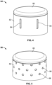
- At least one of the lid 64 and the cup sidewall 69 includes a venting geometry for venting combustion gas from the combustion cup 62.
- at least one of the lid 64 and the cup sidewall 69 may include an axially elongated venting geometry that is gradually revealed in response to movement of the lid 64 away from the cup sidewall 69.
- the axially elongated venting geometry may be in the form of at least one axially elongated hole 94, at least two axially spaced apart holes 96, and combinations thereof.
- the axially elongated venting geometry is provided in the lid sidewall 82.
- the lid 64 is illustrated to include a plurality of axially elongated holes 94.
- the lid 64 includes six axially elongated holes 94 equally spaced circumferentially about the lid sidewall 82.
- the axially elongated holes 94 may be similarly shaped.
- the lid 64 may include a greater or lesser number of axially elongated holes 94 within the scope of the present teachings. It will also be understood that the holes 94 may be shaped differently or sized differently.
- the lid 98 includes an elongated venting geometry in the form of a plurality of axially spaced holes 96. As shown, the holes 96 are circular. Alternatively, the holes 96 may be elongated or of any other shape. The holes 96 may be arranged in circumferentially extending rows. As illustrated, the sidewall 82 of the lid 98 includes three rows of holes. The circumferentially extending rows of holes may axially spaced from one another.
- an inflator 10 in accordance with the present teachings can provide operation performance in accordance with selected operating conditions as may be required or desired for particular inflatable restraint system installations and applications. More specifically, an inflator 10 of the present teachings can be actuated in a manner such that either or both the quantity or rate of inflation gas production can be appropriately varied, such as at the time of a vehicle crash or collision incident, to take into account one or more conditions of occupant presence.
- Such inflator performance adaptability results is provided by the two discrete and ballistically isolated chambers of gas generant materials of the inflator 10 of the present teachings.
- such an inflator 10 may be operated to have a first stage discharge in which the igniter material 49 is ignited to produce combustion products which are passed to the first chamber 34 to combust the first gas generant material 36.
- inflation gas may be produced at a first output level without actuating or firing the second igniter device 84 or reacting or without activating the gas generant material 68 contained in the second chamber 66.
- such operation may be desired to provide a minimized or reduced inflator output such as may be desired in an instance of a low speed collision, for example.
- an inflator 10 in accordance with the present teachings may be operated such that both the first and second igniter devices 50 and 84 are actuated.
- first and second igniter devices 50 and 84 and first and second gas generant materials 36 and 68 may involve the simultaneous or near simultaneous actuation and firing of the first and second igniter devices 50 and 84.
- simultaneous or near simultaneous actuation may be desired to provide a rapid inflation and deployment of an associated airbag cushion.
- this rapid inflation and deployment may be desired in response to a high speed or severe vehicle collision.
- sequential actuation and firing of the first and second igniter devices 50 and 84 may be desired in response to detection of a moderately severe vehicle collision.
- the time lag or delay between the actuation and firing of the first and second squibs and, in turn, the combustion of the first and second gas generant materials 36 and 68 may be tailored to meet the specific requirements for a particular inflatable restraint system installation, as will be appreciated by those skilled in the art.
- inflator assemblies are particularly suited for application as adaptive output inflators in that they may be made generally dependent on one or more selected operating conditions such as ambient temperature, occupant presence, seat belt usage and rate of deceleration of the motor vehicle, for example.
- the second gas generant material 68 is combusted to produce reaction products, resulting in an increase in pressure within the cup interior 66.
- the increase of pressure within the cup interior 66 displaces the lid 64 away from the combustion cup 62 to gradually reveal the elongated venting geometry in the lid sidewall 82.
- the gradual reveal of the elongated venting geometry functions to longer maintain the pressure within the combustion chamber 66.
- the second gas generant material 68 may be more thoroughly combusted and associated effluents are reduced.
- the present teachings provide a dual stage inflator 10 having a combustion cup 62 with a lid 80 that has an increased volume for gas generant loading as compared to a conventional combustion cup with a constant diameter.
- the dual stage inflator 10 of the present teachings may realize an increase in volume of at least 5%, preferably at least 10% and more preferably at least 15%. In one example, the present teachings provided an increase in volume of approximately 19.85%.
Landscapes
- Physics & Mathematics (AREA)
- Fluid Mechanics (AREA)
- Engineering & Computer Science (AREA)
- Mechanical Engineering (AREA)
- Air Bags (AREA)
Claims (8)
- Dispositif de gonflage à deux étages (10) pour un dispositif gonflable de sécurité de véhicule, le dispositif de gonflage à deux étages (10) comprenant :un boîtier (12) définissant une première chambre (34) contenant un premier matériau générateur de gaz (36) ;une coupelle d'allumage (46) disposée dans la première chambre (34) et définissant un intérieur contenant un matériau d'allumage (49) ;un premier dispositif d'allumage (50) s'étendant à l'intérieur de la coupelle d'allumage (46) ;une coupelle de combustion (62) et un couvercle (64) disposés dans la première chambre (34) et coopérant pour définir une seconde chambre (66) contenant un second matériau générateur de gaz (68), la coupelle de combustion (62) comportant une paroi latérale de coupelle (69) s'étendant entre une première extrémité axiale (70) et une seconde extrémité axiale (72), la première extrémité axiale (70) étant une extrémité ouverte, le couvercle (64) étant normalement en position fermée par rapport à la coupelle de combustion (62) pour fermer l'extrémité ouverte (70) de la coupelle de combustion (62), le couvercle (64) pouvant être éloigné de la coupelle de combustion (62) en réponse à une augmentation de pression à l'intérieur de la coupelle de combustion (62) pour évacuer le gaz de combustion hors de la coupelle de combustion (62) ; etun second dispositif d'allumage (84) s'étendant dans la chambre de combustion (62) et fermant la seconde extrémité axiale (72) de la chambre de combustion (62) ;dans lequel :la coupelle de combustion (62) comporte une première partie s'étendant axialement (74) adjacente à la première extrémité axiale (70) ayant un premier diamètre externe et une seconde partie s'étendant axialement (76) adjacente à la seconde extrémité axiale (72) ayant un deuxième diamètre externe, le premier diamètre externe étant inférieur au deuxième diamètre externe, etdans lequel le couvercle (64) comporte une paroi latérale de couvercle (82) s'étendant dans une direction axiale et chevauchant radialement au moins une partie de la coupelle de combustion (62) comportant le premier diamètre externe,dans lequel le dispositif de gonflage à deux étages (10) comprend un filtre (40) disposé radialement entre la paroi latérale de coupelle (69) et le boîtier (12),caractérisé en ce que la paroi latérale de couvercle (82) a une épaisseur dans une direction radiale, la seconde partie s'étendant axialement (76) de la coupelle de combustion (62) étant positionnée plus près du filtre (40) dans la direction radiale que l'épaisseur de la paroi latérale de couvercle (82).
- Dispositif de gonflage à deux étages (10) selon la revendication 1,
caractérisé en ce que la paroi latérale de coupelle (69) comporte une partie conique (78) entre la première partie s'étendant axialement (74) et la seconde partie s'étendant axialement (76). - Dispositif de gonflage à deux étages (10) selon l'une des revendications précédentes, caractérisé en ce que la paroi latérale de couvercle (82) comporte une géométrie d'évacuation pour évacuer le gaz de combustion de la seconde chambre (66) révélée en réponse au mouvement du couvercle (64) loin de la paroi latérale de coupelle (69).
- Dispositif de gonflage à deux étages (10) selon l'une des revendications précédentes, caractérisé en ce que la paroi latérale de couvercle (82) a un troisième diamètre externe, le troisième diamètre externe n'étant pas plus grand que le premier diamètre externe.
- Dispositif de gonflage à deux étages (10) selon l'une des revendications précédentes, caractérisé en ce que la paroi latérale de couvercle (69) a un troisième diamètre externe, le troisième diamètre externe étant sensiblement égal au premier diamètre externe.
- Dispositif de gonflage à deux étages (10) selon l'une des revendications précédentes, caractérisé en ce que la coupelle de combustion (62) comporte en outre une bride circonférentielle s'étendant axialement (86) au niveau de la seconde extrémité axiale (72), la bride circonférentielle s'étendant axialement (86) définissant une ouverture recevant le second dispositif d'allumage (84), l'ouverture définie par la bride circonférentielle s'étendant axialement (86) ayant un quatrième diamètre, le quatrième diamètre étant de préférence plus petit que le premier diamètre externe.
- Dispositif de gonflage à deux étages (10) selon la revendication 6,
caractérisé en ce que la bride circonférentielle s'étendant axialement (86) s'étend loin de la seconde partie s'étendant axialement (72) de la coupelle de combustion (62). - Dispositif de gonflage à deux étages selon la revendication 6,
caractérisé en ce que la coupelle de combustion (62) comporte en outre une paroi d'extrémité (87) s'étendant radialement entre la bride circonférentielle s'étendant axialement (86) et la seconde partie s'étendant axialement (72).
Applications Claiming Priority (2)
| Application Number | Priority Date | Filing Date | Title |
|---|---|---|---|
| US17/203,880 US11479205B2 (en) | 2021-03-17 | 2021-03-17 | Dual stage inflator |
| PCT/US2022/019433 WO2022197498A1 (fr) | 2021-03-17 | 2022-03-09 | Dispositif de gonflage à deux étages |
Publications (2)
| Publication Number | Publication Date |
|---|---|
| EP4308421A1 EP4308421A1 (fr) | 2024-01-24 |
| EP4308421B1 true EP4308421B1 (fr) | 2025-05-14 |
Family
ID=81385008
Family Applications (1)
| Application Number | Title | Priority Date | Filing Date |
|---|---|---|---|
| EP22718345.6A Active EP4308421B1 (fr) | 2021-03-17 | 2022-03-09 | Gonfleur à deux phases |
Country Status (4)
| Country | Link |
|---|---|
| US (1) | US11479205B2 (fr) |
| EP (1) | EP4308421B1 (fr) |
| CN (1) | CN116888018B (fr) |
| WO (1) | WO2022197498A1 (fr) |
Family Cites Families (11)
| Publication number | Priority date | Publication date | Assignee | Title |
|---|---|---|---|---|
| JP2963086B1 (ja) * | 1997-12-26 | 1999-10-12 | ダイセル化学工業株式会社 | エアバッグ用ガス発生器及びエアバッグ装置 |
| EP1447285B1 (fr) * | 1999-02-16 | 2008-05-14 | Daicel Chemical Industries, Ltd. | Générateur de gaz à niveaux multiples pour coussin gonflable et dispositif à coussin gonflable |
| US6189927B1 (en) | 1999-12-16 | 2001-02-20 | Autoliv Asp, Inc. | Adaptive output inflator |
| US20030146611A1 (en) | 2002-02-06 | 2003-08-07 | Kenney Steven B. | Adaptive output passenger disk inflator |
| US6983956B2 (en) * | 2003-08-14 | 2006-01-10 | Key Safety Systems, Inc. | Dual stage pyrotechnic inflator |
| US7044502B2 (en) * | 2004-02-24 | 2006-05-16 | Key Safety Systems, Inc. | Dual stage pyrotechnic driver inflator |
| US7374204B2 (en) * | 2005-11-28 | 2008-05-20 | Autoliv Asp, Inc. | Inflator second stage combustion control |
| JP5016620B2 (ja) * | 2009-01-15 | 2012-09-05 | 株式会社ダイセル | 車両の人員拘束装置用ガス発生器 |
| JP5611840B2 (ja) * | 2009-01-22 | 2014-10-22 | オートリブ エー・エス・ピー・インク | エアバッグ装置用ガス発生器 |
| JP5945152B2 (ja) * | 2012-04-25 | 2016-07-05 | 株式会社ダイセル | ガス発生器 |
| JP6282555B2 (ja) * | 2014-08-01 | 2018-02-21 | 株式会社ダイセル | ガス発生器 |
-
2021
- 2021-03-17 US US17/203,880 patent/US11479205B2/en active Active
-
2022
- 2022-03-09 EP EP22718345.6A patent/EP4308421B1/fr active Active
- 2022-03-09 WO PCT/US2022/019433 patent/WO2022197498A1/fr not_active Ceased
- 2022-03-09 CN CN202280015087.2A patent/CN116888018B/zh active Active
Also Published As
| Publication number | Publication date |
|---|---|
| WO2022197498A1 (fr) | 2022-09-22 |
| CN116888018B (zh) | 2026-02-17 |
| US20220297632A1 (en) | 2022-09-22 |
| CN116888018A (zh) | 2023-10-13 |
| US11479205B2 (en) | 2022-10-25 |
| EP4308421A1 (fr) | 2024-01-24 |
Similar Documents
| Publication | Publication Date | Title |
|---|---|---|
| EP1056624B2 (fr) | Accessoire de gonflage a sortie adaptative | |
| US7950693B2 (en) | Dual stage inflator | |
| US6908104B2 (en) | Pyrotechnic side impact inflator | |
| JP3029326U (ja) | 多段式エアバッグ膨張装置 | |
| US6189927B1 (en) | Adaptive output inflator | |
| US6364353B2 (en) | Dual stage air bag inflator | |
| EP2888136B1 (fr) | Systeme de gonflage de coussin gonflable de securite | |
| EP1361971B1 (fr) | Dispositif de gonflage a deux chambres | |
| US20030146611A1 (en) | Adaptive output passenger disk inflator | |
| JP7325567B2 (ja) | 車両安全装置のガス発生器用イニシエータ | |
| EP1613508B1 (fr) | Systeme de gonflage pour chocs lateraux et pour ceinture de securite | |
| EP2146875B1 (fr) | Dispositif gonfleur à écoulement axial pour installations de retenue gonflables | |
| US11718267B1 (en) | Initiator for a gas generator of a vehicle safety device | |
| US20220281405A1 (en) | Dual stage inflator | |
| EP4308421B1 (fr) | Gonfleur à deux phases | |
| US11603072B2 (en) | Dual stage inflator |
Legal Events
| Date | Code | Title | Description |
|---|---|---|---|
| STAA | Information on the status of an ep patent application or granted ep patent |
Free format text: STATUS: UNKNOWN |
|
| STAA | Information on the status of an ep patent application or granted ep patent |
Free format text: STATUS: THE INTERNATIONAL PUBLICATION HAS BEEN MADE |
|
| PUAI | Public reference made under article 153(3) epc to a published international application that has entered the european phase |
Free format text: ORIGINAL CODE: 0009012 |
|
| STAA | Information on the status of an ep patent application or granted ep patent |
Free format text: STATUS: REQUEST FOR EXAMINATION WAS MADE |
|
| 17P | Request for examination filed |
Effective date: 20231002 |
|
| AK | Designated contracting states |
Kind code of ref document: A1 Designated state(s): AL AT BE BG CH CY CZ DE DK EE ES FI FR GB GR HR HU IE IS IT LI LT LU LV MC MK MT NL NO PL PT RO RS SE SI SK SM TR |
|
| DAV | Request for validation of the european patent (deleted) | ||
| DAX | Request for extension of the european patent (deleted) | ||
| GRAP | Despatch of communication of intention to grant a patent |
Free format text: ORIGINAL CODE: EPIDOSNIGR1 |
|
| STAA | Information on the status of an ep patent application or granted ep patent |
Free format text: STATUS: GRANT OF PATENT IS INTENDED |
|
| INTG | Intention to grant announced |
Effective date: 20241108 |
|
| GRAJ | Information related to disapproval of communication of intention to grant by the applicant or resumption of examination proceedings by the epo deleted |
Free format text: ORIGINAL CODE: EPIDOSDIGR1 |
|
| STAA | Information on the status of an ep patent application or granted ep patent |
Free format text: STATUS: REQUEST FOR EXAMINATION WAS MADE |
|
| GRAP | Despatch of communication of intention to grant a patent |
Free format text: ORIGINAL CODE: EPIDOSNIGR1 |
|
| STAA | Information on the status of an ep patent application or granted ep patent |
Free format text: STATUS: GRANT OF PATENT IS INTENDED |
|
| INTC | Intention to grant announced (deleted) | ||
| INTG | Intention to grant announced |
Effective date: 20250206 |
|
| GRAS | Grant fee paid |
Free format text: ORIGINAL CODE: EPIDOSNIGR3 |
|
| GRAA | (expected) grant |
Free format text: ORIGINAL CODE: 0009210 |
|
| STAA | Information on the status of an ep patent application or granted ep patent |
Free format text: STATUS: THE PATENT HAS BEEN GRANTED |
|
| AK | Designated contracting states |
Kind code of ref document: B1 Designated state(s): AL AT BE BG CH CY CZ DE DK EE ES FI FR GB GR HR HU IE IS IT LI LT LU LV MC MK MT NL NO PL PT RO RS SE SI SK SM TR |
|
| REG | Reference to a national code |
Ref country code: GB Ref legal event code: FG4D |
|
| REG | Reference to a national code |
Ref country code: CH Ref legal event code: EP |
|
| REG | Reference to a national code |
Ref country code: IE Ref legal event code: FG4D |
|
| REG | Reference to a national code |
Ref country code: DE Ref legal event code: R096 Ref document number: 602022014669 Country of ref document: DE |
|
| REG | Reference to a national code |
Ref country code: NL Ref legal event code: MP Effective date: 20250514 |
|
| PG25 | Lapsed in a contracting state [announced via postgrant information from national office to epo] |
Ref country code: FI Free format text: LAPSE BECAUSE OF FAILURE TO SUBMIT A TRANSLATION OF THE DESCRIPTION OR TO PAY THE FEE WITHIN THE PRESCRIBED TIME-LIMIT Effective date: 20250514 Ref country code: ES Free format text: LAPSE BECAUSE OF FAILURE TO SUBMIT A TRANSLATION OF THE DESCRIPTION OR TO PAY THE FEE WITHIN THE PRESCRIBED TIME-LIMIT Effective date: 20250514 Ref country code: PT Free format text: LAPSE BECAUSE OF FAILURE TO SUBMIT A TRANSLATION OF THE DESCRIPTION OR TO PAY THE FEE WITHIN THE PRESCRIBED TIME-LIMIT Effective date: 20250915 |
|
| REG | Reference to a national code |
Ref country code: LT Ref legal event code: MG9D |
|
| PG25 | Lapsed in a contracting state [announced via postgrant information from national office to epo] |
Ref country code: NO Free format text: LAPSE BECAUSE OF FAILURE TO SUBMIT A TRANSLATION OF THE DESCRIPTION OR TO PAY THE FEE WITHIN THE PRESCRIBED TIME-LIMIT Effective date: 20250814 Ref country code: GR Free format text: LAPSE BECAUSE OF FAILURE TO SUBMIT A TRANSLATION OF THE DESCRIPTION OR TO PAY THE FEE WITHIN THE PRESCRIBED TIME-LIMIT Effective date: 20250815 |
|
| PG25 | Lapsed in a contracting state [announced via postgrant information from national office to epo] |
Ref country code: PL Free format text: LAPSE BECAUSE OF FAILURE TO SUBMIT A TRANSLATION OF THE DESCRIPTION OR TO PAY THE FEE WITHIN THE PRESCRIBED TIME-LIMIT Effective date: 20250514 Ref country code: NL Free format text: LAPSE BECAUSE OF FAILURE TO SUBMIT A TRANSLATION OF THE DESCRIPTION OR TO PAY THE FEE WITHIN THE PRESCRIBED TIME-LIMIT Effective date: 20250514 |
|
| REG | Reference to a national code |
Ref country code: AT Ref legal event code: MK05 Ref document number: 1794544 Country of ref document: AT Kind code of ref document: T Effective date: 20250514 |
|
| PG25 | Lapsed in a contracting state [announced via postgrant information from national office to epo] |
Ref country code: BG Free format text: LAPSE BECAUSE OF FAILURE TO SUBMIT A TRANSLATION OF THE DESCRIPTION OR TO PAY THE FEE WITHIN THE PRESCRIBED TIME-LIMIT Effective date: 20250514 |
|
| PG25 | Lapsed in a contracting state [announced via postgrant information from national office to epo] |
Ref country code: HR Free format text: LAPSE BECAUSE OF FAILURE TO SUBMIT A TRANSLATION OF THE DESCRIPTION OR TO PAY THE FEE WITHIN THE PRESCRIBED TIME-LIMIT Effective date: 20250514 |
|
| PG25 | Lapsed in a contracting state [announced via postgrant information from national office to epo] |
Ref country code: AT Free format text: LAPSE BECAUSE OF FAILURE TO SUBMIT A TRANSLATION OF THE DESCRIPTION OR TO PAY THE FEE WITHIN THE PRESCRIBED TIME-LIMIT Effective date: 20250514 |
|
| PG25 | Lapsed in a contracting state [announced via postgrant information from national office to epo] |
Ref country code: RS Free format text: LAPSE BECAUSE OF FAILURE TO SUBMIT A TRANSLATION OF THE DESCRIPTION OR TO PAY THE FEE WITHIN THE PRESCRIBED TIME-LIMIT Effective date: 20250814 |
|
| PG25 | Lapsed in a contracting state [announced via postgrant information from national office to epo] |
Ref country code: IS Free format text: LAPSE BECAUSE OF FAILURE TO SUBMIT A TRANSLATION OF THE DESCRIPTION OR TO PAY THE FEE WITHIN THE PRESCRIBED TIME-LIMIT Effective date: 20250914 |
|
| PG25 | Lapsed in a contracting state [announced via postgrant information from national office to epo] |
Ref country code: LV Free format text: LAPSE BECAUSE OF FAILURE TO SUBMIT A TRANSLATION OF THE DESCRIPTION OR TO PAY THE FEE WITHIN THE PRESCRIBED TIME-LIMIT Effective date: 20250514 |
|
| PG25 | Lapsed in a contracting state [announced via postgrant information from national office to epo] |
Ref country code: DK Free format text: LAPSE BECAUSE OF FAILURE TO SUBMIT A TRANSLATION OF THE DESCRIPTION OR TO PAY THE FEE WITHIN THE PRESCRIBED TIME-LIMIT Effective date: 20250514 Ref country code: SM Free format text: LAPSE BECAUSE OF FAILURE TO SUBMIT A TRANSLATION OF THE DESCRIPTION OR TO PAY THE FEE WITHIN THE PRESCRIBED TIME-LIMIT Effective date: 20250514 |
|
| PG25 | Lapsed in a contracting state [announced via postgrant information from national office to epo] |
Ref country code: CZ Free format text: LAPSE BECAUSE OF FAILURE TO SUBMIT A TRANSLATION OF THE DESCRIPTION OR TO PAY THE FEE WITHIN THE PRESCRIBED TIME-LIMIT Effective date: 20250514 |
|
| PG25 | Lapsed in a contracting state [announced via postgrant information from national office to epo] |
Ref country code: EE Free format text: LAPSE BECAUSE OF FAILURE TO SUBMIT A TRANSLATION OF THE DESCRIPTION OR TO PAY THE FEE WITHIN THE PRESCRIBED TIME-LIMIT Effective date: 20250514 |
|
| PG25 | Lapsed in a contracting state [announced via postgrant information from national office to epo] |
Ref country code: SK Free format text: LAPSE BECAUSE OF FAILURE TO SUBMIT A TRANSLATION OF THE DESCRIPTION OR TO PAY THE FEE WITHIN THE PRESCRIBED TIME-LIMIT Effective date: 20250514 |
|
| PG25 | Lapsed in a contracting state [announced via postgrant information from national office to epo] |
Ref country code: IT Free format text: LAPSE BECAUSE OF FAILURE TO SUBMIT A TRANSLATION OF THE DESCRIPTION OR TO PAY THE FEE WITHIN THE PRESCRIBED TIME-LIMIT Effective date: 20250514 |
|
| REG | Reference to a national code |
Ref country code: DE Ref legal event code: R097 Ref document number: 602022014669 Country of ref document: DE |
|
| PLBE | No opposition filed within time limit |
Free format text: ORIGINAL CODE: 0009261 |
|
| STAA | Information on the status of an ep patent application or granted ep patent |
Free format text: STATUS: NO OPPOSITION FILED WITHIN TIME LIMIT |
|
| REG | Reference to a national code |
Ref country code: CH Ref legal event code: L10 Free format text: ST27 STATUS EVENT CODE: U-0-0-L10-L00 (AS PROVIDED BY THE NATIONAL OFFICE) Effective date: 20260325 |
|
| PGFP | Annual fee paid to national office [announced via postgrant information from national office to epo] |
Ref country code: GB Payment date: 20260319 Year of fee payment: 5 |
|
| PGFP | Annual fee paid to national office [announced via postgrant information from national office to epo] |
Ref country code: DE Payment date: 20260320 Year of fee payment: 5 |
|
| PGFP | Annual fee paid to national office [announced via postgrant information from national office to epo] |
Ref country code: FR Payment date: 20260323 Year of fee payment: 5 |
|
| 26N | No opposition filed |
Effective date: 20260217 |