EP4309791A1 - Appareil et procédé pour fixer une enveloppe de broyage d'un broyeur à cône à un cône de support du broyeur à cône et pour détacher l'enveloppe de broyage du cône de support - Google Patents
Appareil et procédé pour fixer une enveloppe de broyage d'un broyeur à cône à un cône de support du broyeur à cône et pour détacher l'enveloppe de broyage du cône de support Download PDFInfo
- Publication number
- EP4309791A1 EP4309791A1 EP23177755.8A EP23177755A EP4309791A1 EP 4309791 A1 EP4309791 A1 EP 4309791A1 EP 23177755 A EP23177755 A EP 23177755A EP 4309791 A1 EP4309791 A1 EP 4309791A1
- Authority
- EP
- European Patent Office
- Prior art keywords
- cone
- carrier
- pressure plate
- carrier cone
- crushing
- Prior art date
- Legal status (The legal status is an assumption and is not a legal conclusion. Google has not performed a legal analysis and makes no representation as to the accuracy of the status listed.)
- Granted
Links
Images


Classifications
-
- B—PERFORMING OPERATIONS; TRANSPORTING
- B02—CRUSHING, PULVERISING, OR DISINTEGRATING; PREPARATORY TREATMENT OF GRAIN FOR MILLING
- B02C—CRUSHING, PULVERISING, OR DISINTEGRATING IN GENERAL; MILLING GRAIN
- B02C2/00—Crushing or disintegrating by gyratory or cone crushers
- B02C2/005—Lining
-
- B—PERFORMING OPERATIONS; TRANSPORTING
- B02—CRUSHING, PULVERISING, OR DISINTEGRATING; PREPARATORY TREATMENT OF GRAIN FOR MILLING
- B02C—CRUSHING, PULVERISING, OR DISINTEGRATING IN GENERAL; MILLING GRAIN
- B02C23/00—Auxiliary methods or auxiliary devices or accessories specially adapted for crushing or disintegrating not provided for in preceding groups or not specially adapted to apparatus covered by a single preceding group
-
- B—PERFORMING OPERATIONS; TRANSPORTING
- B02—CRUSHING, PULVERISING, OR DISINTEGRATING; PREPARATORY TREATMENT OF GRAIN FOR MILLING
- B02C—CRUSHING, PULVERISING, OR DISINTEGRATING IN GENERAL; MILLING GRAIN
- B02C2/00—Crushing or disintegrating by gyratory or cone crushers
- B02C2/02—Crushing or disintegrating by gyratory or cone crushers eccentrically moved
-
- B—PERFORMING OPERATIONS; TRANSPORTING
- B02—CRUSHING, PULVERISING, OR DISINTEGRATING; PREPARATORY TREATMENT OF GRAIN FOR MILLING
- B02C—CRUSHING, PULVERISING, OR DISINTEGRATING IN GENERAL; MILLING GRAIN
- B02C2/00—Crushing or disintegrating by gyratory or cone crushers
- B02C2/02—Crushing or disintegrating by gyratory or cone crushers eccentrically moved
- B02C2/04—Crushing or disintegrating by gyratory or cone crushers eccentrically moved with vertical axis
-
- B—PERFORMING OPERATIONS; TRANSPORTING
- B02—CRUSHING, PULVERISING, OR DISINTEGRATING; PREPARATORY TREATMENT OF GRAIN FOR MILLING
- B02C—CRUSHING, PULVERISING, OR DISINTEGRATING IN GENERAL; MILLING GRAIN
- B02C2/00—Crushing or disintegrating by gyratory or cone crushers
- B02C2/02—Crushing or disintegrating by gyratory or cone crushers eccentrically moved
- B02C2/04—Crushing or disintegrating by gyratory or cone crushers eccentrically moved with vertical axis
- B02C2/042—Moved by an eccentric weight
-
- B—PERFORMING OPERATIONS; TRANSPORTING
- B02—CRUSHING, PULVERISING, OR DISINTEGRATING; PREPARATORY TREATMENT OF GRAIN FOR MILLING
- B02C—CRUSHING, PULVERISING, OR DISINTEGRATING IN GENERAL; MILLING GRAIN
- B02C2/00—Crushing or disintegrating by gyratory or cone crushers
- B02C2/02—Crushing or disintegrating by gyratory or cone crushers eccentrically moved
- B02C2/04—Crushing or disintegrating by gyratory or cone crushers eccentrically moved with vertical axis
- B02C2/047—Crushing or disintegrating by gyratory or cone crushers eccentrically moved with vertical axis and with head adjusting or controlling mechanisms
-
- B—PERFORMING OPERATIONS; TRANSPORTING
- B02—CRUSHING, PULVERISING, OR DISINTEGRATING; PREPARATORY TREATMENT OF GRAIN FOR MILLING
- B02C—CRUSHING, PULVERISING, OR DISINTEGRATING IN GENERAL; MILLING GRAIN
- B02C2210/00—Codes relating to different types of disintegrating devices
- B02C2210/02—Features for generally used wear parts on beaters, knives, rollers, anvils, linings and the like
Definitions
- the present invention refers to an apparatus for attaching a cone-shaped crushing mantle of a cone crusher to a carrier cone of the cone crusher and for detaching the crushing mantle from the carrier cone, the carrier cone having a carrier cone axis.
- a cone crusher is a compression type of machine that reduces the size of fed material by squeezing or compressing between a moving piece (crushing mantle or inner crushing blade) usually made of steel and a stationary piece (crushing ring or outer crushing blade) usually made of steel.
- the fed material is in particular a mineral material like stone, rock, concrete or the like.
- a cone crusher will usually deliver a 4:1 to 6:1 reduction ratio, although other reduction ratios are available, too. As the closed side setting is set tighter to create a finer output, the volume or throughput capacity of the machine is also reduced.
- the material fed into a cone crusher is crushed between a fixed crushing ring (in other words an outer crushing blade) of an upper part of the crusher's housing (or frame) and a crushing mantle (in other words an inner crushing blade), which rests on a conical seat near the bottom of a carrier cone (in other words a supporting cone or a cone head).
- the crushing mantle is attached to the carrier cone by an appropriate fastening device. Due to the very large forces that occur during the crushing process, the fastening device has to provide for a strong attachment of the crushing mantle to the carrier cone. At the same time the attachment should be torque proof, i.e. the crushing mantle is held from turning with respect to the carrier cone.
- the crushing mantle moves eccentrically in respect to the fixed crushing ring.
- the carrier cone is set into a tumbling or oscillating motion by a driving mechanism of the cone crusher.
- the dimensions of a crushing gap (or chamber) between the fixed crushing ring and the rotating crushing mantle in a certain point along the circumferential direction change continuously.
- the material to be crushed is crushed by squeezing and compressing until it can leave the cone crusher as crushed material through the crushing gap.
- the carrier cone with the crushing mantle is entrained in an oscillating or gyrating motion about a rotational axis, wherein the crushing gap between the crushing mantle and the outer crushing ring varies at each point during the cycle.
- the smallest crusher gap occurring during the cycle is called the closed side setting (CSS) of the cone crusher, and the difference between the maximum and the minimum of the gap is called the stroke of the crusher.
- CCS closed side setting
- the crusher setting and the crusher stroke, as well as the operating speed of the crusher it is possible, among other things, to influence the grain size distribution of the crushed material and the production capacity of the crusher.
- the outer crushing ring as well as the inner crushing mantle are used as wearing parts during operation of the cone crusher and, therefore, have to be replaced from time to time.
- the fastening device must provide for a safe, easy and quick attachment of the crushing mantle to the carrier cone and detachment of the crushing mantle from the carrier cone.
- Various types of fastening devices are known in the state of the art.
- WO 2015/155 205 A1 (AU 2015243593 B2 ) discloses a cone carrier head (12) of a carrier cone (4) which is equipped with two external threads (25, 26) of different diameters.
- a manually actuated attachment nut (16) applies an axial attachment force to the crushing mantle (3) via a pressure ring (11) pressing it against the carrier cone (4).
- the attachment nut (16) uses the lower thread (25) on the cone carrier head (12) with the larger diameter.
- a commercially available hydraulically actuated tensioning nut (15) is screwed onto the upper thread (26) of the cone carrier head (12).
- Hydraulically actuating the tensioning nut (15) makes the nut exert, indirectly through a pressure sleeve (24) and the pressure ring (11), an axial clamping force on the crushing mantle (3) further pressing it against the carrier cone (4).
- the pressure sleeve (24) surrounds the attachment nut (16).
- the pressure sleeve (24) is provided with circumferentially extending cut-out passages through which actuating rods (18) for manually actuating the attachment nut (16) can be put through.
- the cut-out passages have a circumferential extension in order to allow tightening or loosening of the attachment nut (16), when the hydraulically actuated tensioning nut (15) is loaded.
- the disadvantage of the fastening device disclosed in this reference is that the pressure sleeve (24) overlaps the attachment nut (16) radially and tightening and loosening of the attachment nut (16) can only be achieved by a small angle by means of the actuating rods (18) stuck through the cut-out passages in the pressure sleeve (24). With other words, the length of the cut-out passages in the circumferential direction limits a tightening and loosening movement of the attachment nut (16).
- Reference WO 2012/171 778 A2 discloses a fastening device for removably attaching a crushing mantle to a conical seat of a carrier cone.
- the fastening device is adapted to tighten itself during operation of the cone crusher, similar to a clamping screw in angular grinders.
- Screws (36, 136, 232, 332) are provided for loosening the clamping connection between the crushing mantle and the carrier cone tightened during operation. The screws can be loosened individually to relieve the clamping connection.
- No hydraulic device for pre-tensioning the crushing mantle in respect to the carrier cone is provided in this reference.
- the final attachment force develops only gradually during operation of the cone crusher.
- the tightened clamping connection can only be released by loosening the screws (36, 136, 232, 332).
- Reference WO 2020/073 077 A1 discloses a fastening device comprising a hydraulic tensioning nut (115) which is screwed onto an external thread (130) of a carrier cone.
- the tensioning nut (115) presses the crushing mantle (110) downwards onto the carrier cone.
- Lock screws (335) are screwed into the top of the hydraulic tensioning nut (115) and maintain the attachment force after the hydraulic pressure is reduced/ released.
- the disadvantage of the fastening device disclosed in this reference is that the components of the entire hydraulic tensioning nut (115) remain in the cone carrier head during operation.
- Reference DE 1 283 654 discloses a fastening device where an external thread (5) is provided on a cone carrier head (1, 3).
- a sleeve (4) is screwed onto the external thread (5), which comprises another external thread on its outer circumference and contains a hydraulic tensioning device (8, 9) at its lower end.
- the sleeve (4) is screwed on the external thread (5), hydraulic pressure is built up and thus the crushing mantle (2) is pressed onto the carrier cone (1).
- an attachment nut (6) is screwed onto the other external thread of the sleeve (4), the underside of which presses, indirectly by means of an intermediate ring (7), on the crushing mantle (2).
- Reference WO 2010/ 086 488 A1 starts from the prior art known from the previously cited reference, DE 1 283 654 . It discloses an anti-rotation device of a hydraulic tensioning device (13, 18, 19, 20, 21, 24). Screws (14) connect a pressure plate (12) to a carrier cone (4). A first part (11) containing essential components (18, 19, 20, 21) of the hydraulic tensioning device is screwed into an internal thread (15) in the carrier cone (4) or its cone carrier head, respectively. A hydraulic pump (24) of the hydraulic tensioning device is removed after attachment of the crushing mantle (5) to the carrier cone (4) and prior to operation of the cone crusher.
- the apparatus may comprise:
- the method for attaching a cone-shaped crushing mantle of a cone crusher to a carrier cone of the cone crusher and for detaching the crushing mantle from the carrier cone may comprise the steps of:
- release of the pre-tensioning device from the pressure plate includes detaching the piston rod or the rod-shaped element attached thereto from the head region of the carrier cone and pulling it out of the central opening of the pressure plate.
- a major advantage of the present invention is the fact that the hydraulic pre-tensioning device is completely removed from the head region of the carrier cone after the attachment screws, which are assigned to the pressure plate, have been mounted, for instance screwed into and tightened in the head region of the carrier cone thereby firmly attaching the crushing mantle to the carrier cone.
- the hydraulic pre-tensioning device is no longer present in the cone crusher during the intended use of the cone crusher, i.e. during the crushing of the fed material.
- the hydraulic pre-tensioning device is not subject of wear and not exposed to any mechanical stress (e.g. friction, shocks, vibration, etc.) that may occur during the intended use of the cone crusher.
- the hydraulic pre-tensioning device can be easily applied to the pressure plate during the pre-tensioning process, that is prior to pressing the crushing mantle against the carrier cone in the axial direction and prior to tightening or loosening the screws in the head region of the carrier cone during attachment or detachment of the crushing mantle to/from the carrier cone.
- No separate tools are required for applying the hydraulic pre-tensioning device to the pressure plate during the pre-tensioning process.
- the order to tightening or loosening the screws in the head region of the carrier cone is of very little importance. Tightening and loosening of the screws may be effected without a separate tool, e.g. by hand, once the axial clamping force acts on the crushing mantle thereby pressing it against the carrier cone.
- the screws are tightened to a defined torque by means of an appropriate tool, for instance a torque spanner, even with the pre-tensioning device, in order to ensure that all screws are evenly loaded when the pre-tensioning device is removed. Nonetheless, even with the use of a tool, it is advantageous that the torque with which the screws are tightened will be much lower than the torque required without the pre-tensioning device. Furthermore, the invention has a reduced risk of breaking the screws and of damaging the threads of the screws when the crushing mantle is attached to/ detached from the carrier cone.
- an appropriate tool for instance a torque spanner
- An indirect attachment of the piston rod may be provided by means of another rod-shaped element, attached on one end to the piston rod and on the other end to the head region of the carrier cone, for instance by means of the threaded connection.
- the cone-shaped crushing mantle is provided with an opening in its top surface.
- the attachment screws, with which the pressure plate is attached to the head region of the carrier cone thereby pressing the pressure plate onto the top surface of the crushing mantle extend through the crushing mantle's opening.
- the piston rod of the hydraulic pre-tensioning device extends through the central opening of the pressure plate as well as through the opening in the top surface of the crushing mantle.
- Applying the hydraulic pre-tensioning device to the pressure plate preferably comprises a housing of the pre-tensioning device coming to rest on a side of the pressure plate opposite to the carrier cone and a piston rod of the piston of the pre-tensioning device extending through a central opening of the pressure plate and being attached to the head region of the carrier cone.
- the pressure chamber and the piston of the pre-tensioning device are located inside the housing of the pre-tensioning device, i.e. on the side of the pressure plate opposite to the carrier cone.
- Attachment of the piston rod to the head region may be effected by means of a threaded connection or in any other suitable way.
- the piston rod comprises an external thread which is screwed into a threaded hole provided in the head region of the carrier cone.
- the apparatus comprises at least three, preferably five or seven, particularly preferred eight attachment screws.
- the attachment screws are preferably evenly distributed in respect to each other in a circumferential direction around the carrier cone axis, i.e. all neighbouring screws have the same circumferential distance in respect to each other.
- the pressure plate is always spaced apart from the carrier cone or its head region, respectively, so that the crushing mantle can be braced in respect to the carrier cone by activating the pre-tensioning device, pulling the carrier cone or its head region, respectively, towards the pressure plate and accordingly pressing the pressure plate onto the top surface of the crushing mantle.
- the pressure plate comprises at least two other holes (e.g. through holes or blind holes) adapted for receiving fixing means of a protective cap, outside the pre-tensioning process, when the cone-shaped crushing mantle has been firmly attached to the carrier cone and when the hydraulic pre-tensioning device has been released and removed from the pressure plate.
- the protective cap covers the pressure plate and the attachment screws during the intended use of the cone crusher.
- the protective cap is preferably made of steel, in particular a particularly hard steel, e.g. a medium or high carbon steel that has been given heat treatment and then quenching possibly followed by tempering.
- the protective cap is made out of the same wear resistant manganese steel casting as the crushing mantle.
- the at least two other holes are preferably threaded holes and the fixing means of the protective cap are preferably screws which are screwed into the threaded holes of the pressure plate.
- the screw heads for fastening the protective cap to the pressure plate are preferably recessed in a top surface of the protective cap in order to experience the least possible wear during intended use of the cone crusher.
- the pressure plate has a slanted peripheral surface and is adapted to rest with its slanted peripheral surface on the top surface of the crushing mantle.
- the slanted peripheral surface of the pressure plate rests on a similarly slanted inner circumferential surface surrounding an opening provided in the top surface of the crushing mantle.
- the crushing mantle in its top surface has an opening with an inclined inner circumferential surface surrounding the opening and the pressure plate is adapted to rest with its slanted peripheral surface on the inclined inner circumferential surface of the crushing mantle.
- the pressure plate has a collar- or sleeve-like section extending from a plate-like section of the pressure plate in an axial direction towards the crushing mantle.
- This embodiment of the pressure plate provides additional space between the plate-like section of the pressure plate and a top surface of the carrier cone or its head region, respectively.
- the additional space can be used by part of the carrier cone or its head region, respectively, extending through an opening in the top surface of the crushing mantle.
- the head region of the carrier cone comprises multiple parts attached to each other, for instance by means of friction or one or more threaded connections.
- the slanted peripheral surface, with which the pressure plate rests on the top surface of the crushing mantle, is preferably provided on a distal circumferential end of the collar- or sleeve-like section of the pressure plate opposite to the plate-like section of the pressure plate.
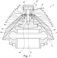
- Fig. 1 shows an apparatus 2 according to a first embodiment of the present invention.
- the apparatus 2 serves for attaching a cone-shaped crushing mantle 4 of a cone crusher, in particular of a mobile cone crusher, to a carrier cone 6 of the cone crusher and for detaching the crushing mantle 4 from the carrier cone 6.
- a cone crusher is described in detail in prior art reference WO 2010/ 086 488 A1 ( US 8944356 ) which is incorporated herein by reference in its entirety.
- a mobile cone crusher is mounted onto a chassis provided with wheels, skids, chains or tracks in order to load the cone crusher on a transporter, to drive the cone crusher to its destined place of operation and to align it at its place of operation.
- the mobile cone crusher may be self-propelled or moved by a propelling vehicle.
- a cone crusher 100 according to the present invention is shown in detail in Fig. 5 .
- the cone crusher 100 is a compression type of machine that reduces the size of fed material by squeezing or compressing between a moving piece (crushing mantle 4 or inner crushing blade) usually made of steel and a stationary piece (crushing ring 102 or outer crushing blade) usually made of steel.
- the fed material is in particular a mineral material like stone, rock, concrete or the like.
- the crushing mantle 4 moves eccentrically in respect to the fixed crushing ring 102.
- the carrier cone 6 is set into a tumbling or oscillating motion by a driving mechanism 104 of the cone crusher 100.
- the driving mechanism 104 comprises a drive shaft 106 and a bevel gear 108.
- the drive shaft 106 is driven by a motor (not shown).
- the dimensions of a crushing gap 110 (or chamber 112) between the fixed crushing ring 102 and the rotating crushing mantle 4 in a certain point along the circumferential direction change continuously.
- the material to be crushed is crushed by squeezing and compressing until it can leave the cone crusher 100 as crushed material through the crushing gap 110.
- the carrier cone 6 with the crushing mantle 4 is entrained in an oscillating or gyrating motion about a rotational axis, wherein the crushing gap 110 between the crushing mantle 4 and the outer crushing ring 102 varies at each point during the cycle.
- the smallest crusher gap 110 occurring during the cycle is called the closed side setting (CSS) of the cone crusher 100, and the difference between the maximum and the minimum of the gap 110 is called the stroke of the crusher 100.
- CCS closed side setting
- the crusher setting and the crusher stroke, as well as the operating speed of the crusher 100 it is possible, among other things, to influence the grain size distribution of the crushed material and the production capacity of the crusher 100.
- the outer crushing ring 102 as well as the inner crushing mantle 4 are used as wearing parts during operation of the cone crusher 100 and, therefore, have to be replaced from time to time.
- the apparatus 2 according to the invention is provided for easy and fast attachment and detachment of a crushing mantle 4 to/ from the carrier cone 6.
- the apparatus 2 is used in a cone crusher 100 according to the invention.
- the apparatus 2 comprises a pressure plate 10 adapted for resting on a top surface 12 of the crushing mantle 4.
- the pressure plate 10 comprises a central opening 14 and at least two through holes 16 located around the central opening 14 preferably equidistantly in respect to each other in a circumferential direction. Neighbouring through holes 16 could also be located in different circumferential distances in respect to each other. Preferably, the through holes 16 have the same distance in respect to the carrier cone axis 8.
- the through holes 16 may also take the form of and are intended to comprise not only round holes but also slots, cut outs or the like of any given cross sectional area.
- the apparatus 2 further comprises at least two attachment screws 18, wherein one of the screws 18 is assigned to each of the at least two through holes 16.
- Each of the screws 18 is adapted to be inserted into the through hole 16 to which it is assigned and to be screwed into a head region 20 of the carrier cone 6.
- the head region 20 is provided with threaded blind holes 22, one for each screw 18.
- the apparatus 2 comprises a hydraulically actuated pre-tensioning device 24, which may also be referred to as a pre-tensioning actuator 24, adapted for pressing the crushing mantle 4 against the carrier cone 6 in a pre-tensioning process in the axial direction prior to tightening the attachment screws 18 in the head region 20 of the carrier cone 6 during attachment of the crushing mantle 4 to the carrier cone 6 and prior to loosening the screws 18 in the head region 20 of the carrier cone 6 during detachment of the crushing mantle 4 from the carrier cone 6.
- the hydraulic pre-tensioning device 24 comprises a pressure chamber 26 and a piston 28 limiting the pressure chamber 26.
- the pressure chamber 26 and the piston 28 are provided inside a housing 30 of the pre-tensioning device 24.
- the pressure chamber 26 is adapted for receiving a pressurized hydraulic medium, e.g. a fluid medium like oil, water or the like.
- a pressurized hydraulic medium e.g. a fluid medium like oil, water or the like.
- a hose or tube 34 for the pressurized hydraulic medium may be attached to the port 32.
- a hydraulic pressure generation device (not shown), like a hydraulic pump, may be attached to an end of the hose or tube 34 opposite to the port 32.
- the hydraulic pressure generation device could also make part of the hydraulic pre-tensioning device 24 and be located inside the housing 30.
- the hydraulic pressure is generated inside the device 24 and the internal hydraulic pressure generation device would supply the pressurized hydraulic; the hose or tube 34 and the connection to the port 32 would merely have to be fluid tight and to resist rather low pressure values.
- the actual high pressure of the hydraulic medium could then be generated inside the hydraulic pre-tensioning device 24. In that case, it would be sufficient if a simple container for the hydraulic fluid, e.g. a fluid tank or the like, was attached to the hose or tube 34 opposite to the port 32.
- the hydraulic pre-tensioning device 24 is adapted to be applied externally to the pressure plate 10 during the pre-tensioning process, such that a piston rod 36 of the piston 28 extends through the central opening 14 of the pressure plate 10 and is attached to the head region 20 of the carrier cone 6.
- Applying the hydraulic pre-tensioning device 24 to the pressure plate 10 preferably comprises the housing 30 of the pre-tensioning device 24 coming to rest on a side of the pressure plate 10 opposite to the carrier cone 6 and the piston rod 36 of the piston 28 of the pre-tensioning device 24 extending through the central opening 14 of the pressure plate 14 and being attached to the head region 20 of the carrier cone 6.
- the housing 30 is located on a side of the pressure plate 10 opposite to the carrier cone 6.
- the pressure chamber 26 and the piston 28 of the hydraulic pre-tensioning device 24 are located on the side of the pressure plate 10 opposite to the carrier cone 6.
- Attachment of the piston rod 36 to the head region 20 of the carrier cone 6 may be realized directly or indirectly by means of a threaded connection 38, comprising an external thread on the outer circumferential surface of the piston rod 36 and an internal thread in a blind hole 40 of the head region 20.
- a threaded connection 38 comprising an external thread on the outer circumferential surface of the piston rod 36 and an internal thread in a blind hole 40 of the head region 20.
- An indirect attachment of the piston rod 36 may be provided by means of another rod-shaped element (not shown), attached on one end to the piston rod 36 and on the other end to the head region 20 of the carrier cone 6, for instance by means of the threaded connection 38.
- the hydraulic pre-tensioning device 24 is further adapted to be released and removed from the pressure plate 10 outside the pre-tensioning process, i.e. before or after the pre-tensioning process.
- Releasing the pre-tensioning device 24 includes detaching the piston rod 36 - or in the case of an indirect attachment of the piston rod 36, the other rod-shaped element - from the head region 20 of the carrier cone 6 and pulling it out of the central opening 14 of the pressure plate 10.
- Alternate embodiments could have the piston rod 36 left in the head region 20 of the carrier cone 6 or turned further into the head region 20 after the hydraulic pre-tensioning device 24 is removed.
- the pressure plate 10 presses the crushing mantle 4 onto the carrier cone 6.
- the pressure plate 10 is fixed to the head region 20 of the cone 6 by the attachment screws 18.
- the number of screws 18 may be three, preferably five or seven and particularly preferable eight.
- the screws 18 are preferably located equidistantly in respect to the carrier cone axis 8 and neighbouring screws 18 are preferably located equidistantly in a circumferential direction.
- these screws 18 provide for the attachment force for holding the crushing mantle 4 on the carrier cone 6.
- the hydraulic pre-tensioning device 24 is used for an easy and quick assembly and disassembly of the attachment screws 18.
- Dismounting the hydraulic pre-tensioning device 24 may comprise detaching the piston rod 36 from the head region 20 of the carrier cone 6 and removing the piston rod 36 through the central opening 14 of the pressure plate 10. Alternate embodiments could have the piston rod 36 left in the head region 20 of the carrier cone 6 or turned further into the head region 20 after the hydraulic pre-tensioning device 24 is removed.
- Re-tightening the attachment screws 18 is preferably performed with the help of a suitable tool, e.g. a hand wrench.
- the screws 18 may be tightened to a specific torque to ensure equal sharing of the load.
- the torque will be significantly lower than the torque required without the pre-tensioning device 24.
- Dismounting the hydraulic pre-tensioning device 24 may comprise detaching the piston rod 36 from the head region 20 of the carrier cone 6 and removing the piston rod 36 through the central opening 14 of the pressure plate 10. Alternate embodiments could have the piston rod 36 left in the head region 20 of the carrier cone 6 or turned further into the head region 20 after the hydraulic pre-tensioning device 24 is removed. It is emphasized that the piston rod 36 does not need to be removed until a new crushing mantle 4 is installed.
- Loosening the attachment screws 18 is preferably performed with the help of a suitable tool, e.g. a hand wrench.
- the assembly and disassembly of the crushing mantle 4 on/ from the carrier cone 6 is fast, easy and safe. Even if in exceptional situations the hydraulic pre-tensioning device 24 is not available, it is possible to assemble or disassemble the crushing mantle 4 from the carrier cone 6 in the conventional way. In this case the attachment screws 18 would have to be tightened and loosened with the help of a standard tool, for instance a hand wrench, in a predefined distinct order, in order to avoid tension and canting.
- a standard tool for instance a hand wrench
- a major advantage of the present invention is the fact that the hydraulic pre-tensioning device 24 is completely removed from the head region 20 of the carrier cone 6 after the attachment screws 18, which are assigned to the pressure plate 10, have been screwed into and tightened in the head region 20 of the carrier cone 6 thereby firmly attaching the crushing mantle 4 to the carrier cone 6.
- the hydraulic pre-tensioning device 24 is no longer present in the cone crusher 100 during the intended use of the cone crusher 100, i.e. during the crushing of the fed material.
- the hydraulic pre-tensioning device 24 is not exposed to any mechanical stress (e.g. friction, shocks, vibration, etc.) that may occur during the intended use of the cone crusher 100.
- the cone-shaped crushing mantle 4 is provided with an opening 42 in its top surface 12.
- the opening 42 is delimited and surrounded by a ring-shaped inner circumferential surface of the top surface 12 having a slanted extension when viewed in a sectional view comprising the carrier cone axis 8.
- the pressure plate 10 has a correspondingly slanted peripheral surface 44 and is adapted to rest with its slanted peripheral surface 44 on the slanted inner circumferential surface of the top surface 12 of the crushing mantle 4.
- the attachment screws 18, with which the pressure plate 10 is attached to the head region 20 of the carrier cone 6 thereby pressing the pressure plate 10 onto the top surface 12 of the crushing mantle 4 extend through the crushing mantle's opening 42.
- the piston rod 36 of the hydraulic pre-tensioning device 24 extends through the central opening 14 of the pressure plate 10 as well as through the opening 42 in the top surface 12 of the crushing mantle 4.
- the pressure plate 10 is always spaced apart from the carrier cone 6 or its head region 20, respectively, in an axial direction, so that the crushing mantle 4 can be braced in respect to the carrier cone 6 by activating the pre-tensioning device 24, thereby pulling the carrier cone 6 or its head region 20, respectively, towards the pressure plate 10 and accordingly pressing the pressure plate 10 onto the top surface 12 of the crushing mantle 4.
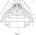
- the pressure plate 10 comprises at least two other holes 46 (e.g. through holes or blind holes) adapted for receiving fixing means 48 (cf. Fig. 2 ) of a protective cap 50, outside the pre-tensioning process, when the cone-shaped crushing mantle 4 has been firmly attached to the carrier cone 6 and when the hydraulic pre-tensioning device 24 has been released and removed from the pressure plate 10.
- the protective cap 50 covers the pressure plate 10 and the attachment screws 18 during the intended use of the cone crusher 100.
- the protective cap 50 is preferably made of steel, in particular a particularly hard steel, e.g. a medium or high carbon steel that has been given heat treatment and then quenching possibly followed by tempering.
- the protective cap 50 is made out of the same wear resistant manganese steel casting as the crushing mantle 4.
- the at least two other holes 46 are preferably threaded holes and the fixing means 48 of the protective cap 50 are preferably screws which are screwed into the threaded holes 46 of the pressure plate 10.
- the screw heads 52 for fastening the protective cap 50 to the pressure plate 10 are preferably recessed in a top surface 54 of the protective cap 50 in order to experience the least possible wear during intended use of the cone crusher 100.
- the carrier cone 6 has an anchoring element 56, which is introduced into a respective opening in the head region 20 of the carrier cone 6 from below.
- the anchoring element 56 has a collar 58 extending in an essentially radial direction thereby providing a contact surface 60 with which the anchoring element 56 abuts against the rest of the carrier cone 6 after insertion into the opening in the head region 20.
- the anchoring element 56 may constitute part of or the entire head region 20 of the carrier cone 6.
- the threaded blind hole 40 is provided in the anchoring element 56.
- the threaded blind holes 22 are also provided in the anchoring element 56.
- the carrier cone 6 could also be realized as a single component without the separate anchoring element 56.
- the carrier cone 6 has a sleeve-like element 62 which is inserted and fixed in a hole of the anchoring element 56.
- the sleeve-like element 62 is fixed in the opening of the anchoring element 56 by means of a threaded connection 64 comprising an external thread on the external circumferential surface of the sleeve-like element 62 and an internal thread in the lateral walls of the hole of the anchoring element 56.
- the sleeve-like element 62 has a collar 66 extending in an essentially radial direction.
- the sleeve-like element 62 constitutes part of the head region 20 of the carrier cone 6.
- the threaded blind hole 40 is provided in the sleeve-like element 62.
- the threaded blind holes 22 are provided in the collar 66 of the sleeve-like element 62.
- the carrier cone 6 could also be realized as a single component without the separate anchoring element 56 and sleeve-like element 62.
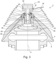
- the pressure plate 10 of Figs. 3 and 4 has a collar- or sleeve-like section 68 extending from a plate-like section 70 of the pressure plate 10 in an axial direction towards the crushing mantle 4. It may be sufficient if the collar- or sleeve-like section 68 has an axial component of extension. It is not necessary for the collar- or sleeve-like section 68 to extend exclusively in the axial direction. In Figs. 3 and 4 the collar- or sleeve-like section 68 also has a radial component of extension.
- Such a design of the pressure plate 10 provides additional space between the plate-like section 70 of the pressure plate 10 and a top surface of the carrier cone 6 or its head region 20, respectively.
- the top surface of the carrier cone 6 is formed by a surface of the sleeve-like element 62 facing the plate-like section 70 of the pressure plate 10.
- the additional space is particularly advantageous if the head region 20 of the carrier cone 6 comprises multiple parts, like parts 6, 56, 62, attached to each other, for instance by means of friction or one or more threaded connections.
- the slanted peripheral surface 44 with which the pressure plate 10 rests on the top surface 12 of the crushing mantle 4, is preferably provided on a distal circumferential end of the collar- or sleeve-like section 68 of the pressure plate 10 opposite to the plate-like section 70 of the pressure plate 10.
- the top part of the sleeve-like element 62, in particular the collar 66 are arranged in the additional space provided within the pressure plate 10 or its collar- or sleeve-like section 68, respectively.
Landscapes
- Engineering & Computer Science (AREA)
- Food Science & Technology (AREA)
- Mechanical Engineering (AREA)
- Crushing And Grinding (AREA)
Applications Claiming Priority (1)
| Application Number | Priority Date | Filing Date | Title |
|---|---|---|---|
| US17/867,849 US11911773B2 (en) | 2022-07-19 | 2022-07-19 | Apparatus and method for attaching a crushing mantle of a cone crusher to a carrier cone of the cone crusher and for detaching the crushing mantle from the carrier cone |
Publications (3)
| Publication Number | Publication Date |
|---|---|
| EP4309791A1 true EP4309791A1 (fr) | 2024-01-24 |
| EP4309791C0 EP4309791C0 (fr) | 2024-12-11 |
| EP4309791B1 EP4309791B1 (fr) | 2024-12-11 |
Family
ID=86731991
Family Applications (1)
| Application Number | Title | Priority Date | Filing Date |
|---|---|---|---|
| EP23177755.8A Active EP4309791B1 (fr) | 2022-07-19 | 2023-06-06 | Appareil et procédé pour fixer une enveloppe de broyage d'un broyeur à cône à un cône de support du broyeur à cône et pour détacher l'enveloppe de broyage du cône de support |
Country Status (3)
| Country | Link |
|---|---|
| US (1) | US11911773B2 (fr) |
| EP (1) | EP4309791B1 (fr) |
| CN (1) | CN117414891B (fr) |
Citations (6)
| Publication number | Priority date | Publication date | Assignee | Title |
|---|---|---|---|---|
| DE1283654B (de) | 1966-03-10 | 1968-11-21 | Kloeckner Humboldt Deutz Ag | Kreiselbrecher mit hydraulischer Spannvorrichtung fuer den Ein- und Ausbau des Brechkegels |
| US20060086852A1 (en) * | 2004-10-25 | 2006-04-27 | Johnson Crushers International | Bowl liner retaining method and apparatus |
| WO2010086488A1 (fr) | 2009-01-29 | 2010-08-05 | Metso Minerals Inc. | Dispositif de fixation, concasseur à cône et procédé pour la fixation d'un manteau sur une tête d'un concasseur à cône |
| WO2012171778A2 (fr) | 2011-06-17 | 2012-12-20 | Sandvik Intellectual Property Ab | Broyeur, enveloppe de broyage et procédé de fixation d'enveloppe de broyage |
| WO2015155205A1 (fr) | 2014-04-09 | 2015-10-15 | Thyssenkrupp Industrial Solutions Ag | Fixation du cône de concassage dans un concasseur à cône |
| WO2020073077A1 (fr) | 2018-10-09 | 2020-04-16 | Technofast Industries Pty Ltd | Système d'ensemble manchon hydraulique pour concasseur giratoire |
Family Cites Families (10)
| Publication number | Priority date | Publication date | Assignee | Title |
|---|---|---|---|---|
| BR112012005258A2 (pt) | 2009-09-08 | 2019-09-24 | Crushing And Mining Equipment Pty Ltd | dispositivo de elevação de manto e método para elevar um manto |
| FI124186B (fi) | 2012-10-26 | 2014-04-30 | Metso Minerals Inc | Menetelmä kara- tai kartiomurskaimen sisemmän kulutusosan nostamiseksi, sisempi kulutusosa ja kara- tai kartiomurskain |
| EP2921235B1 (fr) | 2014-03-18 | 2016-10-12 | Sandvik Intellectual Property AB | Outil de levage de coque de concasseur giratoire |
| WO2016169622A1 (fr) | 2015-04-24 | 2016-10-27 | Sandvik Intellectual Property Ab | Dispositif de levage de coque de broyeur giratoire |
| EP3454990B1 (fr) * | 2016-05-10 | 2020-06-24 | FLSmidth A/S | Ensemble boulon de verrouillage pour un dispositif de broyage |
| CN106732910A (zh) * | 2017-01-20 | 2017-05-31 | 河南黎明重工科技股份有限公司 | 一种复合式单缸液压圆锥破碎机 |
| EP3616794A1 (fr) | 2018-08-30 | 2020-03-04 | Metso Minerals OY | Dispositif, agencement et procédé de levage de manteau de concassage |
| CN209155935U (zh) * | 2018-09-13 | 2019-07-26 | 上海云统创申智能科技有限公司 | 圆锥破碎机的圆锥破碎部 |
| CN211677905U (zh) * | 2019-12-11 | 2020-10-16 | 郑州杰美隆矿机有限公司 | 一种用于多缸破碎机的破碎壁锁紧装置 |
| US11679389B2 (en) * | 2021-05-21 | 2023-06-20 | Metso Outotec USA Inc. | Mantle retaining system and method for a gyratory crusher |
-
2022
- 2022-07-19 US US17/867,849 patent/US11911773B2/en active Active
-
2023
- 2023-06-06 EP EP23177755.8A patent/EP4309791B1/fr active Active
- 2023-06-26 CN CN202310760471.1A patent/CN117414891B/zh active Active
Patent Citations (10)
| Publication number | Priority date | Publication date | Assignee | Title |
|---|---|---|---|---|
| DE1283654B (de) | 1966-03-10 | 1968-11-21 | Kloeckner Humboldt Deutz Ag | Kreiselbrecher mit hydraulischer Spannvorrichtung fuer den Ein- und Ausbau des Brechkegels |
| US20060086852A1 (en) * | 2004-10-25 | 2006-04-27 | Johnson Crushers International | Bowl liner retaining method and apparatus |
| WO2010086488A1 (fr) | 2009-01-29 | 2010-08-05 | Metso Minerals Inc. | Dispositif de fixation, concasseur à cône et procédé pour la fixation d'un manteau sur une tête d'un concasseur à cône |
| US8944356B2 (en) | 2009-01-29 | 2015-02-03 | Metso Minerals Inc. | Fastening device, a cone crusher and a method for fastening an inner crushing blade to a head of a cone crusher |
| WO2012171778A2 (fr) | 2011-06-17 | 2012-12-20 | Sandvik Intellectual Property Ab | Broyeur, enveloppe de broyage et procédé de fixation d'enveloppe de broyage |
| US20140110514A1 (en) | 2011-06-17 | 2014-04-24 | Sandvik Intellectual Property Ab | Crusher, crushing shell, and method of attaching crushing shell |
| WO2015155205A1 (fr) | 2014-04-09 | 2015-10-15 | Thyssenkrupp Industrial Solutions Ag | Fixation du cône de concassage dans un concasseur à cône |
| AU2015243593B2 (en) | 2014-04-09 | 2018-11-15 | Flsmidth A/S | Fastening of the crushing cone in a cone crusher |
| WO2020073077A1 (fr) | 2018-10-09 | 2020-04-16 | Technofast Industries Pty Ltd | Système d'ensemble manchon hydraulique pour concasseur giratoire |
| US20210322995A1 (en) | 2018-10-09 | 2021-10-21 | Technofast Industries Pty. Ltd. | Hydraulic Mantle Assembly System for a Gyratory Rock Crusher |
Also Published As
| Publication number | Publication date |
|---|---|
| CN117414891A (zh) | 2024-01-19 |
| US11911773B2 (en) | 2024-02-27 |
| EP4309791C0 (fr) | 2024-12-11 |
| CN117414891B (zh) | 2025-11-14 |
| EP4309791B1 (fr) | 2024-12-11 |
| US20240024883A1 (en) | 2024-01-25 |
Similar Documents
| Publication | Publication Date | Title |
|---|---|---|
| US8832921B2 (en) | Locking nut assembly for a cone crusher | |
| EP2382047B1 (fr) | Dispositif de fixation, concasseur à cône et procédé pour la fixation d'un manteau sur une tête d'un concasseur à cône | |
| US9561508B2 (en) | Roller for high pressure roller grinder, roller grinder, and method for assembling a roller for a roller grinder | |
| CN217594675U (zh) | 保持器组件及回转破碎机 | |
| AU2015243593B2 (en) | Fastening of the crushing cone in a cone crusher | |
| JP7836490B2 (ja) | ねじ締結体用の締付け装置と、安全装置とから成るアセンブリ | |
| EP4309791B1 (fr) | Appareil et procédé pour fixer une enveloppe de broyage d'un broyeur à cône à un cône de support du broyeur à cône et pour détacher l'enveloppe de broyage du cône de support | |
| CN112770843A (zh) | 用于回转式碎石机的液压罩壳组装系统 | |
| EP3454990B1 (fr) | Ensemble boulon de verrouillage pour un dispositif de broyage | |
| CN102834034A (zh) | 轧碎机清除系统 | |
| AU2017371388A1 (en) | Liner bolt | |
| CN216396458U (zh) | 关键衬垫节段、一组衬垫节段、顶壳、以及回转破碎机或圆锥破碎机 | |
| EA046981B1 (ru) | Система фиксации брони и способ для гирационной дробилки | |
| CN113400254A (zh) | 一种自锁机构的螺纹分解装置 | |
| HK1183642B (en) | Roller for high pressure roller grinder, roller grinder, and method for assembling a roller for a roller grinder |
Legal Events
| Date | Code | Title | Description |
|---|---|---|---|
| PUAI | Public reference made under article 153(3) epc to a published international application that has entered the european phase |
Free format text: ORIGINAL CODE: 0009012 |
|
| STAA | Information on the status of an ep patent application or granted ep patent |
Free format text: STATUS: THE APPLICATION HAS BEEN PUBLISHED |
|
| AK | Designated contracting states |
Kind code of ref document: A1 Designated state(s): AL AT BE BG CH CY CZ DE DK EE ES FI FR GB GR HR HU IE IS IT LI LT LU LV MC ME MK MT NL NO PL PT RO RS SE SI SK SM TR |
|
| STAA | Information on the status of an ep patent application or granted ep patent |
Free format text: STATUS: REQUEST FOR EXAMINATION WAS MADE |
|
| REG | Reference to a national code |
Ref country code: DE Ref legal event code: R079 Free format text: PREVIOUS MAIN CLASS: B02C0002000000 Ipc: B02C0002020000 Ref country code: DE Ref legal event code: R079 Ref document number: 602023001315 Country of ref document: DE Free format text: PREVIOUS MAIN CLASS: B02C0002000000 Ipc: B02C0002020000 |
|
| 17P | Request for examination filed |
Effective date: 20240705 |
|
| RBV | Designated contracting states (corrected) |
Designated state(s): AL AT BE BG CH CY CZ DE DK EE ES FI FR GB GR HR HU IE IS IT LI LT LU LV MC ME MK MT NL NO PL PT RO RS SE SI SK SM TR |
|
| GRAP | Despatch of communication of intention to grant a patent |
Free format text: ORIGINAL CODE: EPIDOSNIGR1 |
|
| STAA | Information on the status of an ep patent application or granted ep patent |
Free format text: STATUS: GRANT OF PATENT IS INTENDED |
|
| RIC1 | Information provided on ipc code assigned before grant |
Ipc: B02C 2/00 20060101ALI20240808BHEP Ipc: B02C 2/04 20060101ALI20240808BHEP Ipc: B02C 2/02 20060101AFI20240808BHEP |
|
| INTG | Intention to grant announced |
Effective date: 20240821 |
|
| GRAS | Grant fee paid |
Free format text: ORIGINAL CODE: EPIDOSNIGR3 |
|
| GRAA | (expected) grant |
Free format text: ORIGINAL CODE: 0009210 |
|
| STAA | Information on the status of an ep patent application or granted ep patent |
Free format text: STATUS: THE PATENT HAS BEEN GRANTED |
|
| AK | Designated contracting states |
Kind code of ref document: B1 Designated state(s): AL AT BE BG CH CY CZ DE DK EE ES FI FR GB GR HR HU IE IS IT LI LT LU LV MC ME MK MT NL NO PL PT RO RS SE SI SK SM TR |
|
| REG | Reference to a national code |
Ref country code: GB Ref legal event code: FG4D |
|
| REG | Reference to a national code |
Ref country code: CH Ref legal event code: EP |
|
| REG | Reference to a national code |
Ref country code: IE Ref legal event code: FG4D |
|
| REG | Reference to a national code |
Ref country code: DE Ref legal event code: R096 Ref document number: 602023001315 Country of ref document: DE |
|
| U01 | Request for unitary effect filed |
Effective date: 20241211 |
|
| U07 | Unitary effect registered |
Designated state(s): AT BE BG DE DK EE FI FR IT LT LU LV MT NL PT RO SE SI Effective date: 20241217 |
|
| PG25 | Lapsed in a contracting state [announced via postgrant information from national office to epo] |
Ref country code: HR Free format text: LAPSE BECAUSE OF FAILURE TO SUBMIT A TRANSLATION OF THE DESCRIPTION OR TO PAY THE FEE WITHIN THE PRESCRIBED TIME-LIMIT Effective date: 20241211 |
|
| PG25 | Lapsed in a contracting state [announced via postgrant information from national office to epo] |
Ref country code: ES Free format text: LAPSE BECAUSE OF FAILURE TO SUBMIT A TRANSLATION OF THE DESCRIPTION OR TO PAY THE FEE WITHIN THE PRESCRIBED TIME-LIMIT Effective date: 20241211 |
|
| PG25 | Lapsed in a contracting state [announced via postgrant information from national office to epo] |
Ref country code: NO Free format text: LAPSE BECAUSE OF FAILURE TO SUBMIT A TRANSLATION OF THE DESCRIPTION OR TO PAY THE FEE WITHIN THE PRESCRIBED TIME-LIMIT Effective date: 20250311 |
|
| PG25 | Lapsed in a contracting state [announced via postgrant information from national office to epo] |
Ref country code: GR Free format text: LAPSE BECAUSE OF FAILURE TO SUBMIT A TRANSLATION OF THE DESCRIPTION OR TO PAY THE FEE WITHIN THE PRESCRIBED TIME-LIMIT Effective date: 20250312 |
|
| PG25 | Lapsed in a contracting state [announced via postgrant information from national office to epo] |
Ref country code: RS Free format text: LAPSE BECAUSE OF FAILURE TO SUBMIT A TRANSLATION OF THE DESCRIPTION OR TO PAY THE FEE WITHIN THE PRESCRIBED TIME-LIMIT Effective date: 20250311 |
|
| PG25 | Lapsed in a contracting state [announced via postgrant information from national office to epo] |
Ref country code: SM Free format text: LAPSE BECAUSE OF FAILURE TO SUBMIT A TRANSLATION OF THE DESCRIPTION OR TO PAY THE FEE WITHIN THE PRESCRIBED TIME-LIMIT Effective date: 20241211 |
|
| PG25 | Lapsed in a contracting state [announced via postgrant information from national office to epo] |
Ref country code: PL Free format text: LAPSE BECAUSE OF FAILURE TO SUBMIT A TRANSLATION OF THE DESCRIPTION OR TO PAY THE FEE WITHIN THE PRESCRIBED TIME-LIMIT Effective date: 20241211 |
|
| PG25 | Lapsed in a contracting state [announced via postgrant information from national office to epo] |
Ref country code: IS Free format text: LAPSE BECAUSE OF FAILURE TO SUBMIT A TRANSLATION OF THE DESCRIPTION OR TO PAY THE FEE WITHIN THE PRESCRIBED TIME-LIMIT Effective date: 20250411 |
|
| PG25 | Lapsed in a contracting state [announced via postgrant information from national office to epo] |
Ref country code: SK Free format text: LAPSE BECAUSE OF FAILURE TO SUBMIT A TRANSLATION OF THE DESCRIPTION OR TO PAY THE FEE WITHIN THE PRESCRIBED TIME-LIMIT Effective date: 20241211 |
|
| PG25 | Lapsed in a contracting state [announced via postgrant information from national office to epo] |
Ref country code: CZ Free format text: LAPSE BECAUSE OF FAILURE TO SUBMIT A TRANSLATION OF THE DESCRIPTION OR TO PAY THE FEE WITHIN THE PRESCRIBED TIME-LIMIT Effective date: 20241211 |
|
| U20 | Renewal fee for the european patent with unitary effect paid |
Year of fee payment: 3 Effective date: 20250623 |
|
| PLBE | No opposition filed within time limit |
Free format text: ORIGINAL CODE: 0009261 |
|
| STAA | Information on the status of an ep patent application or granted ep patent |
Free format text: STATUS: NO OPPOSITION FILED WITHIN TIME LIMIT |
|
| 26N | No opposition filed |
Effective date: 20250912 |
|
| PG25 | Lapsed in a contracting state [announced via postgrant information from national office to epo] |
Ref country code: MC Free format text: LAPSE BECAUSE OF FAILURE TO SUBMIT A TRANSLATION OF THE DESCRIPTION OR TO PAY THE FEE WITHIN THE PRESCRIBED TIME-LIMIT Effective date: 20241211 |
|
| PG25 | Lapsed in a contracting state [announced via postgrant information from national office to epo] |
Ref country code: IE Free format text: LAPSE BECAUSE OF NON-PAYMENT OF DUE FEES Effective date: 20250606 |