EP4309795B1 - Dispositif mobile de traitement de roche avec planification améliorée d'une tâche de matériau discontinue - Google Patents
Dispositif mobile de traitement de roche avec planification améliorée d'une tâche de matériau discontinue Download PDFInfo
- Publication number
- EP4309795B1 EP4309795B1 EP23185111.4A EP23185111A EP4309795B1 EP 4309795 B1 EP4309795 B1 EP 4309795B1 EP 23185111 A EP23185111 A EP 23185111A EP 4309795 B1 EP4309795 B1 EP 4309795B1
- Authority
- EP
- European Patent Office
- Prior art keywords
- rock processing
- processing apparatus
- loading
- fed
- rock
- Prior art date
- Legal status (The legal status is an assumption and is not a legal conclusion. Google has not performed a legal analysis and makes no representation as to the accuracy of the status listed.)
- Active
Links
Images

Classifications
-
- B—PERFORMING OPERATIONS; TRANSPORTING
- B02—CRUSHING, PULVERISING, OR DISINTEGRATING; PREPARATORY TREATMENT OF GRAIN FOR MILLING
- B02C—CRUSHING, PULVERISING, OR DISINTEGRATING IN GENERAL; MILLING GRAIN
- B02C13/00—Disintegrating by mills having rotary beater elements ; Hammer mills
- B02C13/02—Disintegrating by mills having rotary beater elements ; Hammer mills with horizontal rotor shaft
- B02C13/06—Disintegrating by mills having rotary beater elements ; Hammer mills with horizontal rotor shaft with beaters rigidly connected to the rotor
- B02C13/09—Disintegrating by mills having rotary beater elements ; Hammer mills with horizontal rotor shaft with beaters rigidly connected to the rotor and throwing the material against an anvil or impact plate
-
- B—PERFORMING OPERATIONS; TRANSPORTING
- B02—CRUSHING, PULVERISING, OR DISINTEGRATING; PREPARATORY TREATMENT OF GRAIN FOR MILLING
- B02C—CRUSHING, PULVERISING, OR DISINTEGRATING IN GENERAL; MILLING GRAIN
- B02C11/00—Other auxiliary devices or accessories specially adapted for grain mills
- B02C11/04—Feeding devices
-
- B—PERFORMING OPERATIONS; TRANSPORTING
- B02—CRUSHING, PULVERISING, OR DISINTEGRATING; PREPARATORY TREATMENT OF GRAIN FOR MILLING
- B02C—CRUSHING, PULVERISING, OR DISINTEGRATING IN GENERAL; MILLING GRAIN
- B02C13/00—Disintegrating by mills having rotary beater elements ; Hammer mills
- B02C13/02—Disintegrating by mills having rotary beater elements ; Hammer mills with horizontal rotor shaft
- B02C13/06—Disintegrating by mills having rotary beater elements ; Hammer mills with horizontal rotor shaft with beaters rigidly connected to the rotor
-
- B—PERFORMING OPERATIONS; TRANSPORTING
- B02—CRUSHING, PULVERISING, OR DISINTEGRATING; PREPARATORY TREATMENT OF GRAIN FOR MILLING
- B02C—CRUSHING, PULVERISING, OR DISINTEGRATING IN GENERAL; MILLING GRAIN
- B02C13/00—Disintegrating by mills having rotary beater elements ; Hammer mills
- B02C13/26—Details
-
- B—PERFORMING OPERATIONS; TRANSPORTING
- B02—CRUSHING, PULVERISING, OR DISINTEGRATING; PREPARATORY TREATMENT OF GRAIN FOR MILLING
- B02C—CRUSHING, PULVERISING, OR DISINTEGRATING IN GENERAL; MILLING GRAIN
- B02C13/00—Disintegrating by mills having rotary beater elements ; Hammer mills
- B02C13/26—Details
- B02C13/286—Feeding or discharge
-
- B—PERFORMING OPERATIONS; TRANSPORTING
- B02—CRUSHING, PULVERISING, OR DISINTEGRATING; PREPARATORY TREATMENT OF GRAIN FOR MILLING
- B02C—CRUSHING, PULVERISING, OR DISINTEGRATING IN GENERAL; MILLING GRAIN
- B02C21/00—Disintegrating plant with or without drying of the material
- B02C21/02—Transportable disintegrating plant
-
- B—PERFORMING OPERATIONS; TRANSPORTING
- B02—CRUSHING, PULVERISING, OR DISINTEGRATING; PREPARATORY TREATMENT OF GRAIN FOR MILLING
- B02C—CRUSHING, PULVERISING, OR DISINTEGRATING IN GENERAL; MILLING GRAIN
- B02C23/00—Auxiliary methods or auxiliary devices or accessories specially adapted for crushing or disintegrating not provided for in preceding groups or not specially adapted to apparatus covered by a single preceding group
- B02C23/02—Feeding devices
-
- B—PERFORMING OPERATIONS; TRANSPORTING
- B02—CRUSHING, PULVERISING, OR DISINTEGRATING; PREPARATORY TREATMENT OF GRAIN FOR MILLING
- B02C—CRUSHING, PULVERISING, OR DISINTEGRATING IN GENERAL; MILLING GRAIN
- B02C23/00—Auxiliary methods or auxiliary devices or accessories specially adapted for crushing or disintegrating not provided for in preceding groups or not specially adapted to apparatus covered by a single preceding group
- B02C23/08—Separating or sorting of material, associated with crushing or disintegrating
- B02C23/10—Separating or sorting of material, associated with crushing or disintegrating with separator arranged in discharge path of crushing or disintegrating zone
- B02C23/12—Separating or sorting of material, associated with crushing or disintegrating with separator arranged in discharge path of crushing or disintegrating zone with return of oversize material to crushing or disintegrating zone
-
- B—PERFORMING OPERATIONS; TRANSPORTING
- B02—CRUSHING, PULVERISING, OR DISINTEGRATING; PREPARATORY TREATMENT OF GRAIN FOR MILLING
- B02C—CRUSHING, PULVERISING, OR DISINTEGRATING IN GENERAL; MILLING GRAIN
- B02C23/00—Auxiliary methods or auxiliary devices or accessories specially adapted for crushing or disintegrating not provided for in preceding groups or not specially adapted to apparatus covered by a single preceding group
- B02C23/08—Separating or sorting of material, associated with crushing or disintegrating
- B02C23/14—Separating or sorting of material, associated with crushing or disintegrating with more than one separator
-
- B—PERFORMING OPERATIONS; TRANSPORTING
- B02—CRUSHING, PULVERISING, OR DISINTEGRATING; PREPARATORY TREATMENT OF GRAIN FOR MILLING
- B02C—CRUSHING, PULVERISING, OR DISINTEGRATING IN GENERAL; MILLING GRAIN
- B02C25/00—Control arrangements specially adapted for crushing or disintegrating
-
- B—PERFORMING OPERATIONS; TRANSPORTING
- B07—SEPARATING SOLIDS FROM SOLIDS; SORTING
- B07B—SEPARATING SOLIDS FROM SOLIDS BY SIEVING, SCREENING, SIFTING OR BY USING GAS CURRENTS; SEPARATING BY OTHER DRY METHODS APPLICABLE TO BULK MATERIAL, e.g. LOOSE ARTICLES FIT TO BE HANDLED LIKE BULK MATERIAL
- B07B1/00—Sieving, screening, sifting, or sorting solid materials using networks, gratings, grids, or the like
- B07B1/005—Transportable screening plants
-
- B—PERFORMING OPERATIONS; TRANSPORTING
- B02—CRUSHING, PULVERISING, OR DISINTEGRATING; PREPARATORY TREATMENT OF GRAIN FOR MILLING
- B02C—CRUSHING, PULVERISING, OR DISINTEGRATING IN GENERAL; MILLING GRAIN
- B02C13/00—Disintegrating by mills having rotary beater elements ; Hammer mills
- B02C13/26—Details
- B02C13/286—Feeding or discharge
- B02C2013/28609—Discharge means
-
- B—PERFORMING OPERATIONS; TRANSPORTING
- B02—CRUSHING, PULVERISING, OR DISINTEGRATING; PREPARATORY TREATMENT OF GRAIN FOR MILLING
- B02C—CRUSHING, PULVERISING, OR DISINTEGRATING IN GENERAL; MILLING GRAIN
- B02C13/00—Disintegrating by mills having rotary beater elements ; Hammer mills
- B02C13/26—Details
- B02C13/286—Feeding or discharge
- B02C2013/28618—Feeding means
-
- B—PERFORMING OPERATIONS; TRANSPORTING
- B02—CRUSHING, PULVERISING, OR DISINTEGRATING; PREPARATORY TREATMENT OF GRAIN FOR MILLING
- B02C—CRUSHING, PULVERISING, OR DISINTEGRATING IN GENERAL; MILLING GRAIN
- B02C9/00—Other milling methods or mills specially adapted for grain
- B02C9/04—Systems or sequences of operations; Plant
Definitions
- the present invention relates in particular to a mobile rock processing device with a chassis which allows the rock processing device to change its installation location in a self-propelled manner and/or to move in a self-propelled manner between an installation location for a rock processing operation and a means of transport for transporting the rock processing device.
- the undercarriage is usually a crawler undercarriage, although a wheeled undercarriage as an alternative or in addition to a crawler undercarriage should not be excluded.
- a rock processing device of the above-mentioned type is known from US 4,281,800 known.
- the previously known rock processing device comprises both a screening device and a crushing device and is part of a rock processing plant with a rock mill downstream of the rock processing device in the material flow.
- the rock processing device is continuously loaded with material to be processed from a quarry by a conveyor belt.
- the US 4,281,800 proposes to determine a work output, expressed as a quantity of material per time, of the rock processing device for a future period of time on the basis of a work output of the rock processing plant determined for a complete period of operation, such as one operating day, and a previous respective work output of the rock mill on the one hand and the rock processing device on the other hand already completed since the beginning of the operating period under consideration up to the time of determination within the operating period under consideration.
- the conveying capacity of the conveyor belt loading the rock processing device should be set for the future period of time.
- the US 4,909,449 Furthermore, it is disclosed to change the conveying capacity of a conveying device between the material buffer and a crushing device, depending on the filling level of material to be processed in the material buffer and/or on the motor load of a discharge conveyor device which conveys processed material out of the rock processing device.
- the US 2021/0325899 A1 discloses the targeted control of a tipper body of conveyor trucks which load a rock processing device in order to influence the unloading of the conveyor truck over a desired unloading period.
- a specific tipping profile of the tipper body is to be achieved in order to unload starting material transported in the tipper body to the rock processing device at a desired material discharge rate.
- the lighting system described above indicates the current readiness of the rock processing device to be processed depending on the filling level of the material to be processed in the material buffer, which basically only helps but does not ensure that the rock processing device is not overloaded.
- An undersupply of the rock processing device with material to be processed can still occur, as the lighting system only indicates that the device is ready to be loaded when it actually exists. If the device is ready to be loaded at short notice, the material buffer and the subsequent work unit can run dry or at least be underfilled, with the associated known disadvantages, as personnel at the loading devices may not be able to react quickly enough to the sudden display of the device's readiness to be loaded.
- the present invention achieves the stated object of a rock processing device of the generic type in that the control device is designed to determine, in an operation with discontinuous material feed of starting material to be processed, on the basis of the at least one detection signal, time information which indicates an execution time of a future material feed into the material feeding device, wherein the output device is designed to output the determined time information.
- the control device can determine a future requirement of the rock processing device for material to be processed on the basis of the at least one detection signal and thus predict it as time information.
- third parties such as a machine operator of a loading device, can take note of the time information and consequently plan their material feed into the rock processing device in advance.
- the determined and output time information can be processed automatically by a data processing device, such as a control device, of at least one loading device and its loading operation can be set up and carried out taking the time information into account, so that material can actually be fed into the material feed device at the execution time represented by the time information.
- the at least one operating parameter can be recorded qualitatively and/or quantitatively. If more than one operating parameter is recorded, then some of the operating parameters can be recorded qualitatively and others can be recorded quantitatively. It is also conceivable that at least one operating parameter is recorded both quantitatively and qualitatively.
- the execution time can be an execution point in time and/or an execution time range.
- the execution time can specify the earliest possible future point in time at or from which material can or should be fed into the material feed device.
- the execution time can additionally or alternatively specify a future period of time over which material can or should be fed into the feed device.
- the time information can be relative time information related to a reference time, such as the current actual time.
- the time information can be in the form of a waiting time until the next material task is issued.
- the time information can be absolute time information, which represents an execution time or a start of an execution time period as a time in the relevant time zone. If necessary, an end of the execution time period can again be absolute time information or relative time information, preferably related to the start of the execution time period. As a rule, however, it will be sufficient to specify the point in time as the execution time from which a material task can take place in the future.
- the execution time represented by the time information is in the future. This is not just a theoretical future due to signal transmission times in the micro- or nanosecond range, but a future that is at least in the single-digit second range away from the time the time information is output. The execution time will often be in the two-digit or even three- or four-digit second range away from the time the time information is output in the future.
- the rock processing device is preferably designed to determine an individual execution time as time information for at least two, particularly preferably for more than two, consecutive future material tasks in operation with discontinuous material feed and to output it by means of the output device.
- the execution times of a series of consecutive material tasks can thus be determined individually for the operating situation of the rock processing device that develops further as a result of the previous material feed, depending on the at least one operating parameter represented by the at least one detection signal, and output as time information.
- the rock processing device can have only one or more screening devices as the at least one working unit.
- the rock processing device is then a pure screening plant.
- the rock processing device can have only one or more crushing devices as the at least one working unit.
- the rock processing device is then a pure crushing plant.
- the rock processing device comprises both at least one screening device and at least one crushing device.
- the screening device can be a pre-screen arranged upstream of the crushing device in the material flow, optionally with several screen decks, and/or can be a post-screen arranged downstream of the crushing device in the material flow in order to sort the result provided by the crushing device according to grain size.
- the post-screen can also comprise at least one screen deck or several screen decks.
- the crushing device may be any known crushing device such as an impact crusher or a jaw crusher or a cone crusher or a roller crusher. Then, when the rock processing device has more than one crushing device, these crushing devices may be similar crushing devices or different crushing devices. Each individual crushing device may be one of the above-mentioned crusher types from impact crusher, jaw crusher, cone crusher and roller crusher.
- the rock processing device comprises an input device for inputting information, wherein the input device for transmitting information is connected to the control device in terms of signal transmission.
- the control device is preferably designed to determine the time information in operation with discontinuous material feed on the basis of the at least one detection signal and information entered into the input device.
- the input device may be any input device, such as a keyboard, a touch screen, and the like.
- the input device may also be a cable or a radio link can be connected to the control device for signal transmission, so that it does not necessarily have to be physically present on the rock processing device.
- a connection with the interposition of a data storage device in which information entered into the input device and/or information output by the at least one sensor for detecting the at least one operating parameter is also considered a signal transmission connection of the input device or of the at least one sensor to the control device, in which information entered into the input device and/or information output by the at least one sensor for detecting the at least one operating parameter is stored as data and retrieved as stored data by the control device.
- the control device therefore preferably comprises a data storage device which is connected to the control device for signal transmission.
- the control device can store data supplied by the input device and/or by the at least one sensor and retrieve it again as stored data.
- the input device and/or the at least one sensor can be connected directly to the data storage device for signal transmission, so that the input device can transfer information entered into it directly to the data storage device for storage, just as the at least one sensor can transfer the results of its detection operation.
- Data that does not change over the service life of the rock processing device or can only be changed with great effort can be stored permanently in the data storage and can be stored, for example, by the manufacturer of the rock processing device during its manufacture or before its delivery. Should the machine configuration nevertheless change, for example during maintenance or repair, the company carrying out the maintenance or repair can make corresponding changes to the content of the data storage.
- the data storage device can be physically connected to the control device by a signal line and/or non-physically connected to the control device for signal transmission, for example by a radio link or by transmitting optical signals. In principle, the data storage device can therefore be provided separately and at a distance from the rest of the rock processing device.
- the "remaining rock processing device” is represented by its machine body. The machine body comprises the machine frame and all components of the rock processing device connected to it, even if these are arranged to be movable relative to the machine frame.
- one sensor is sufficient to record an operating parameter.
- one and the same operating parameter can be recorded by several sensors, for example if the aim is to determine a location-dependent local filling level of the material buffer rather than an average one.
- the rock processing device can have more than one sensor. The same applies if more than one physical operating principle is to be used to record one or more operating parameters.
- the filling level of the material buffer can be detected, for example, by one or more ultrasonic sensors. Additionally or alternatively, optical detection by at least one camera as a sensor and/or tactile detection by a mechanical sensor is possible.
- the filling level of the material buffer which is usually funnel-shaped, is a measure of the supply of material still to be processed on the rock processing device.
- the filling level of the material buffer can be represented by a filling height of the material added to the material buffer.
- a single value of the filling height can be used as a representative value for an overall average filling height of the material buffer, or several local filling heights can be determined in order to resolve the filling of the material buffer more locally. It is also conceivable to use optical methods such as laser scanning to determine a profile of the surface of material added to the material buffer and its height above the known bottom of the material buffer.
- the filling height or the local filling heights up to the surface profile of the filled material can already adequately represent the filling level. Alternatively, they can be related to the maximum capacity of the material buffer.
- An overfilled material buffer should be avoided, as should an underfilled material buffer.
- material is lost during the material feed because it can slip off a pile of material in the material buffer and fall next to the material feed device.
- the conveying capacity of the material buffer can be impaired and the screening capacity of a pre-screen downstream of the material buffer can be negatively affected if the material buffer is overloaded.
- overfilling the material buffer can lead to overfilling of a work unit following in the material flow, in particular a crushing device.
- An underfilled feed hopper can lead to a high load on the conveyor device following the material buffer, since material hits the conveyor device directly when it is fed in, which can cause greater wear and higher noise emissions.
- the filling level of the material buffer and its temporal development is a particularly preferred operating parameter for determining the next execution time of a future material feed. If, for example, it is possible to determine when the filling level of the material buffer will reach a predetermined minimum filling level in the future, then this information can be used to determine when the material buffer should be reloaded at the latest in order to avoid it being underfilled.
- a safety margin of time can of course be taken into account so that disruptive influences that are always present at construction sites have no or only a minimal effect on the material flow.
- construction site generally includes all sites where material to be processed by the rock processing device is produced or provided, such as quarries, gravel pits, building demolition sites and the like.
- the term “mineral material” therefore includes both natural and processed mineral material. The latter includes building materials as well as returned oversize grain.
- the filling level of the material buffer is repeatedly recorded in order to determine an emptying rate of the material buffer.
- the rock processing device preferably comprises a time measuring device which is connected to the control device in terms of signal transmission, optionally with the above-mentioned data storage device interposed.
- the or a time measuring device can be integrated into the at least one sensor and/or the input device and/or the control device.
- the control device can assign an event time to detection events of the at least one sensor and/or input events of the at least one input device. From the time interval between at least two event times for a similar event, for example the detection of one and the same operating parameter, the control device can determine a rate of change associated with the respective events.
- the control device can thus determine a rate of change of the fill level from two detections of the fill level of the material buffer and the known time interval between these detection events. From the determined rate of change and a fill level known through detection, the control device can, for example, determine a next execution time by extrapolation, if necessary taking into account the safety margin mentioned above.
- the fill level of at least one conveyor device can be recorded as the or a relevant operating parameter. Preference is given to recording the fill level of a conveyor device that conveys from the material buffer to a work unit, in particular to a crushing device.
- the conveying capacity of a conveyor device that conveys directly from the material buffer influences both the fill level of the material buffer and the fill level of the work unit, in particular the crushing device, to which it conveys material.
- the same applies to recording a conveying speed of at least one conveyor device which in turn is preferably the conveyor device that conveys between the material buffer and the work unit, in particular the crushing device.
- the product of the filling level and the conveying speed of a conveying device provides a measure of the volume conveyed by the conveying device or of the conveying capacity of the conveying device.
- the conveying device can be a belt conveyor or a trough conveyor, the latter preferably using the micro-throw principle as a vibrating conveyor.
- a vibrating conveyor preferably in the form of a trough conveyor, is particularly preferred as a conveying device for conveying between the material buffer and a crushing device.
- the rock processing device can also have a plurality of conveying devices and will usually have such a plurality, for example because the same conveying device is not used as the feed conveyor. from the material buffer to a working unit and as a discharge conveyor from a working unit away from the rock processing device.
- these can use different conveying principles, such as the micro-throw principle described above for vibration conveyors and/or like a belt conveyor, whereby the belt conveyor is generally used as a discharge conveyor due to the smaller grain size occurring in the discharge and a usually more homogeneous grain size distribution.
- the conveying speed of a conveyor device can be determined in different ways.
- the conveying speed can be determined independently of the type of conveyor device by detecting a movement in the conveying direction of a material lying on the conveyor device, for example by means of a light barrier, ultrasound, optical detection and image processing and the like.
- the conveying speed of a belt conveyor can be detected by detecting the speed of a roller cooperating with the conveyor belt, be it a support roller or a drive roller, or by directly detecting the path speed of the conveyor belt.
- the vibration amplitude and the vibration frequency can be a measure of the speed of material lying on a vibrating conveyor, so that detecting the vibration amplitude and the vibration frequency is a detection of variables that represent the conveying speed.
- conveying power can be derived from the drive power of a motor that drives them, so that the conveying power can be indirectly derived from detecting a motor torque and a motor speed.
- the output motor torque can be determined from the motor current drawn.
- the torque delivered is proportional to the product of the pressure drop across the hydraulic motor and its displacement. Otherwise, a torque map can be determined and saved for each motor depending on its control variables. The motor torque can then be determined from the recorded control variables by calling up the torque map from the control device.
- At least one sensor can include the filling level of a working unit of the at least one working unit.
- sensors can be used that use the same physical operating principles to detect the filling level as the aforementioned sensors for determining the filling levels of the material buffer and/or the conveying device.
- the filling level of a crushing device can be detected, for example, by light barriers, ultrasound and the like.
- the working unit can be at least one crushing device from the at least one crushing device and/or can be a screening device from the at least one screening device. Preferably, if present, this is a crushing device. This is particularly significant for jaw crushers and cone crushers, but should not be ignored for impact crushers and roller crushers either.
- the filling level of a crushing device also has a part to play in how quickly a material supply in the material buffer is reduced.
- the filling level of a working unit of the rock processing device is a significant factor influencing the material flow in the rock processing device and thus for the unloading or emptying of the material buffer.
- the filling level of a conveyor device is related to the conveying speed of the conveyor device
- the filling level of a working unit is related to the working speed of the working unit. Therefore, in a preferred development of the present invention, a working speed of a working unit, i.e. at least one crushing device and/or at least one screening device, can be recorded.
- the dimension of a crushing gap i.e. in particular the gap width, of a crushing device can be recorded as the at least one operating parameter.
- a dimension of both an upper and a lower crushing gap on an upper or lower impact rocker and/or the crushing gap ratio of the aforementioned crushing gaps can be recorded as operating parameters.
- Crushing gap dimensions can be recorded by recording a position of an actuator element which moves a movable component which limits the respective crushing gap dimension, so that a position of the actuator element is clearly assigned to a position of the movable component.
- Such a component can be a movable crusher jaw or an impact rocker.
- a calibration can be stored in the above-mentioned data storage device which links a detected position of the actuator element with a crushing gap dimension.
- Operating loads can also be recorded by sensors as operating parameters, for example the operating load of a drive device, such as a central drive unit of the rock processing device, which converts the energy delivered to it into one or more different other forms of energy.
- a drive device can be an internal combustion engine, in particular a diesel engine, which converts the internal calorific value of a fuel into mechanical or kinetic energy on an output shaft.
- An electric motor is also conceivable as such a drive device, which converts electrical energy supplied to it into mechanical or kinetic energy on an output shaft. The same applies to a hydraulic motor.
- an operating load can be determined, for example, from a recording of the speed of the output shaft and a torque delivered at this speed. The recording of speed and torque of a shaft is well known in the prior art.
- an engine torque can be taken from a torque map stored in the data memory using at least one other operating parameter, in which the engine torque is linked to the at least one other operating parameter.
- the operating load of a working unit can be recorded as the at least one operating parameter.
- a crushing device regardless of the specific type of crusher, there is always an input shaft which supplies kinetic energy to a moving part of the crushing device, such as the moving crusher jaw of a jaw crusher, the rotor of an impact crusher, the cone of a cone crusher or the roller of a roller crusher.
- the speed of the input shaft can be measured, if necessary with additional recording and consideration the torque supplied by the input shaft, a measure of the working speed and/or the operating load of the crushing device.
- the torque of the input shaft is the torque of a machine driving the input shaft, possibly converted by at least one gear arranged between the drive machine and the input shaft.
- the working speed of the screening device can be represented by an amplitude and/or a frequency of a periodic screening movement.
- the screening device is also driven by a drive shaft for its periodic movement. Its speed, possibly with additional detection and consideration of the torque supplied by the drive shaft, is also an indicator of the working speed and/or operating load of a screening device. Therefore, a sensor for detecting the working speed or the operating load of the screening device can detect the movement amplitude and/or the movement frequency of the screening device and/or a speed and/or a torque of the drive shaft of the screening device in question.
- the filling level of a conveyor device is related to the conveying speed of the conveyor device
- the filling level of a working unit is related to the working speed of the working unit. Therefore, in a preferred development of the present invention, a working speed of a working unit, i.e. at least one crushing device and/or at least one screening device, can be recorded.
- Another possible operating parameter that can be recorded is the grain shape and/or the grain size of the fed and/or conveyed material and/or the proportion of foreign material in the fed and/or conveyed material, whereby the conveyed material was usually previously fed into the material feed device.
- the distribution of grain sizes, i.e. the frequency of occurrence of individual different grain sizes or grain size ranges, in the fed and/or extracted material can be an operating parameter relevant to the material flow in the rock processing device.
- Grain shapes and/or grain sizes and grain size distributions and/or the proportion of foreign material can be recorded, for example, by image processing.
- the grain size distribution in particular is a key factor influencing the success of a preliminary screening process, which in turn influences the quality of a downstream crushing device and, as a result, the amount of oversized grain produced.
- Foreign material is particularly non-breakable material such as plastic, wood, steel and the like. These foreign materials can disrupt the operating sequence of a rock processing device.
- the grain size and/or the grain size distribution and/or the proportion of foreign material in or from the material fed in is a measure of the potential to occupy the material buffer spatially. Larger grains are generally distributed less evenly than smaller grains during material feeding due to the momentum they receive when pouring into the material buffer and often have lower bulk densities. Foreign material, such as steel reinforcements made of reinforced concrete, can also hinder the effective feeding of material into the material buffer and/or the operation of a subsequent conveying device. Grain shapes and/or grain sizes and/or grain size distributions and/or the proportion of foreign material can be recorded qualitatively and/or quantitatively.
- the oversize grain that is created when crushing rock material is usually fed back into the material buffer and thus contributes to the filling level of the material buffer and to its change behavior over time. Therefore, recording the amount of oversize grain returned, in particular the amount of oversize grain returned per unit of time, is a meaningful operating parameter with regard to the emptying rate of the material buffer.
- the amount of oversize grain returned can be recorded optically and/or by image capture and image processing. In addition or alternatively, It is conceivable to record the weight of oversize material conveyed per unit of time via a returning oversize conveyor belt in order to record the quantity of returned oversize material.
- the mesh size of a sieve of a screening device provides information about which grain sizes or grains in which grain size range are moved in the conveyor lines downstream of the screening device in the material flow.
- the mesh size can be stored as a fixed value in the data storage mentioned above.
- the mesh size can also be recorded randomly using a laser scanner or another optical sensor in order to be able to take into account changes in the mesh size due to operation.
- Meshes can expand over the course of their operational life due to exposure to heavy rock material. Meshes can also become clogged with sticky material over time and thus narrower.
- An influential operating parameter is the type of material fed into the rock processing device and conveyed and processed by it.
- the type of material can be determined by one or more qualitative and/or one or more quantitative parameters.
- a qualitative parameter can, for example, contain "hard rock”, “soft rock”, “reinforced concrete”, “asphalt millings”, “asphalt slab”, “construction waste”, “gravel”, “railway ballast” and/or “other” according to a predefined classification.
- a quantitative parameter can, for example, have specific values for density and/or hardness and/or breakability and/or abrasiveness and/or moisture of the material fed in or conveyed according to recognized and preferably standardized measuring methods. These parameters can also be determined qualitatively, in particular only qualitatively, according to a previously defined classification. For example, parameters can have the qualitative contents "hard”, “medium hard”, “soft”, “good breakability”, “medium breakability”, “poor breakability”, “low moisture”, “medium moisture”, “high moisture” etc. The qualitative gradation can have more than three levels.
- the density can be determined quantitatively, for example, from an optical volume measurement with simultaneous weighing, for example by a scale integrated into a conveyor device.
- the moisture content of the material can be determined using an appropriate moisture sensor.
- the abrasiveness can be determined using an LCPC test.
- the breakability of a material can be determined parallel to the abrasiveness during the LCPC test or determined as a Los Angeles value according to DIN EN 1097-2 in the currently valid version.
- the control device can read out the relevant material values, such as hardness, density, breakability and abrasiveness, from a table stored in the data storage device described above by entering the respective rock type using the input device.
- relevant material values such as hardness, density, breakability and abrasiveness
- the state of the material can be classified, for example, into pre-crushed and non-pre-crushed, where "pre-crushed" refers to a previous crushing by a rock processing device.
- Pre-crushed material can be oversize grain returned in the same rock processing device. Additionally or alternatively, pre-crushed material can be transferred from another rock processing device upstream in the material flow to the rock processing device in question.
- the state of the material can be indicated by a mixing ratio, in particular a mass-related mixing ratio, of pre-crushed and non-pre-crushed material.
- the state of the material can basically be recorded by image processing, such as the grain shape.
- the state can additionally or alternatively be determined by pre-crushed and/or non-pre-crushed material for processing by conveyors conveying the respective rock processing device via data transmission to the control device.
- conveyor scales such as belt or bucket scales
- the respective conveyor can also transmit quantity information about the material in its respective state.
- Another influential operating parameter is the size of a loading tool of a loading device that loads the material buffer discontinuously.
- This is, for example, the volume of an excavator bucket or a wheel bearing as a possible loading device.
- this size can be entered via the above-mentioned input device or can be transmitted by a corresponding transmitting device on the loading tool to a receiving device on the rock processing device that is coordinated with the transmitting device.
- a sensor on the rock processing device such as a laser scanner, can directly detect the size of the loading tool or at least a size range that can be assigned to the loading tool.
- the size of the loading tool is a measure of the amount of material that can be fed into the material buffer with one material feed.
- the size, such as the volume, of the loading tool can also be determined by recording the change in the filling level in the material buffer before and after a material feed process. Additionally or alternatively, the actual feed quantity that has been or is to be fed into the material buffer can be recorded.
- the control device can record the temporal change in the filling level of the material buffer as a function of the other recorded operating parameters by recording several of the above-mentioned parameters, including the filling level of the material buffer, and learn at least a qualitative dependency relationship between the filling level of the material buffer and the other recorded operating parameters by means of artificial intelligence methods, such as deep learning, or other analytical methods. and use it to predict when material will need to be added again. As the operating time increases, the control device's prediction accuracy becomes increasingly more precise using its time information.
- one or more functional or data relationships between the filling level of the material buffer and one or more of the other operating parameters mentioned above can be determined experimentally in advance in test operations of the rock processing device and stored in a suitable form in the data storage.
- suitable forms include formulas, characteristic maps, fuzzy sets or fuzzy quantities and the like.
- the at least one functional or data relationship determined in advance in test operations can be the basis for predicting a future development of the filling level of the material buffer and thus for determining the time information. It can, and this is preferred, also be the basis for continued learning with the help of artificial intelligence methods in the further use of the rock processing device.
- the functional relationships of several rock processing devices learned in this way or further developed through continued learning can be transferred to a central data collection point, such as the device manufacturer or its contractual partner, and evaluated and, for example, consolidated there. After such revision, the improved functional relationships can then be transferred to new and/or existing rock processing devices and used by them as a basis for determining the time information depending on at least one operating parameter.
- target indicates that the parameter in question is not recorded by sensors, but is specified as a target value.
- the control device assumes that the rock processing device and its components are operated with respective actual values that differ from the specified target values only within a predetermined tolerance range and otherwise correspond sufficiently with them. This means that the effort required for sensory recording of operating parameters can be limited to a few highly relevant operating parameters, which include, for example, the filling level of the material buffer, without losing excessive forecast accuracy in the time information.
- the output device can be designed to output information in a type of undirected output, independently of the receiver, into a spatial area that at least partially surrounds the rock processing device and/or adjoins the rock processing device. This preferably means that no receiving device is necessary to reproduce the time information output by the output device in a form that is understandable to humans or electronic data processing devices.
- the output device can thus output the time information in a visually perceptible manner, for example by displaying a time which shows the calculated earliest possible loading time for the next material loading.
- a remaining waiting time until the next loading time can be displayed. This can be done digitally or analogue, graphically or numerically.
- the waiting time until the next loading time can be displayed numerically by a digital clock with a time unit countdown, for example by seconds or by seconds and minutes.
- the waiting time can also be displayed graphically and numerically by an analogue clock or an analogue pointer instrument, for example again with a time unit countdown by corresponding continuous or step-by-step pointer movement.
- the output device can have a display device that can be visually perceived from outside the rock processing device, such as the above-mentioned pointer instrument or a monitor with freely configurable graphic display or a light bar with variable luminous dimensions and the like.
- the rock processing device may comprise a receiving device which is designed separately from a machine body of the rock processing device, is movable relative to the machine body and can be separated or separated from the machine body in order to ensure that the time information arrives directly where it is actually needed.
- the output device then outputs the time information by transmitting it to the receiving device.
- the receiving device is itself designed to output the received time information perceptibly to an operator and/or to process and/or use it to control machine components.
- the receiving device can be permanently installed in another device.
- This is preferably the loading device, particularly preferably a driver's cab of the loading device.
- the receiving device is a portable receiving device, such as a smartphone, a tablet computer or a laptop computer. It can then be carried by a machine operator of the loading device and can thus bring the time information to the attention of the machine operator even if he is not at his loading device. In this way, timely material loading at the rock processing device can be achieved even if the loading device is not immediately ready to load material at the time the time information is output.
- the present invention also relates to a machine combination comprising a rock processing device with a separate, separate or separable receiving device and with a loading device that loads the material buffer of the rock processing device discontinuously.
- the receiving device is preferably arranged in the loading device in order to keep the time information available where it is immediately needed, so that timely loading of the material buffer can be ensured.
- the loading device can be an excavator or a wheel loader, depending on the design of the construction site on which the rock processing device or machine combination is used.
- the receiving device can output the time information graphically and/or acoustically to a machine operator of the loading device, for example via a head-up display, so that after knowing the time information, the operator can take the necessary actions to ensure that the material buffer is loaded on time.
- the receiving device can be coupled to a transport-relevant operating component of the loading device in terms of signal transmission and control this in accordance with the time information.
- a transport-relevant operating component can, for example, be at least one actuator on the loading device, which moves a loading tool of the loading device, such as a bucket of the excavator or wheel loader, to fill it.
- the rock processing device can be part of a rock processing plant that includes multiple rock processing devices.
- these multiple rock processing devices work in a linked manner in the sense that a rock processing device upstream in the material flow feeds a material feed device of a downstream rock processing device with its end grain product or one of its end grain products.
- a rock processing plant is also to be understood as a rock processing device within the meaning of the present application, which has a plurality of rock processing sub-devices.
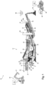
- a construction site is generally designated with 10.
- the central working device of the construction site 10 is a rock processing device 12 with an impact crusher 14 as a crushing device and with a pre-screen 16 and a post-screen 18 as screening devices.
- the construction site is preferably a quarry in the present case, but can also be a recycling center or a demolition site of one or more buildings.
- Material M to be processed by the rock processing device 12, i.e. to be sorted by size and crushed, is fed discontinuously by an excavator 20 as a loading device of the rock processing device 12 into a material feeding device 22 with a funnel-shaped material buffer 24 by loading.
- a vibration conveyor designed as a trough conveyor 26 conveys the material M to the pre-screen 16, which has two pre-screen decks 16a and 16b, of which the upper pre-screen deck 16a has a larger mesh size and separates those grain sizes and feeds them to the impact crusher 14 which require comminution according to the respective specifications for the final grain product to be achieved.
- Grains falling through the upper pre-screen deck 16a are further sorted by the lower pre-screen deck 16b into a useful grain fraction 28, which meets the specifications of the to be achieved final grain product and into an undersize fraction 30, which has such a small grain size that it is unusable as a valuable grain.
- the number of stockpiles or fractions shown in the example is merely an example. It can be larger or smaller than that given in the example.
- the undersize fraction 30, which is explained as rejects in the present example can also be a valuable grain fraction, provided that the grain size range in fraction 30 can be used for other purposes.
- the useful grain fraction 28 is increased by the broken material output from the impact crusher 14 and is conveyed to the secondary screen 18 by a first conveying device 32 in the form of a belt conveyor.
- the secondary screen 18 also has two screen decks or secondary screen decks 18a and 18b, of which the upper secondary screen deck 18a has the larger mesh size.
- the upper secondary screen deck 18a allows valuable grain to fall through its meshes and sorts out an oversize fraction 34 with a grain size that is larger than the largest desired grain size of the valuable grain.
- the oversize fraction 34 is returned to the material input of the impact crusher 14 or to the primary screen 16 by an oversize conveying device 36.
- the oversize conveying device 36 is designed as a belt conveyor in the embodiment shown.
- the useful grain of the useful grain fraction 28 thus includes oversize grain and valuable grain.
- the oversize grain conveyor device 36 can, for example, be pivoted out from a machine frame 50 of the rock processing device 12 so that the oversize grain fraction 34 is stockpiled instead of being returned.
- the valuable grain that has fallen through the mesh of the upper screening deck 18a is further fractionated by the lower screening deck 18b into a fine grain fraction 38 with a smaller grain size and into a medium grain fraction 40 with a larger grain size.
- the fine grain fraction 38 is piled up and stored in a fine grain stockpile 44 by a fine grain discharge conveyor device 42 in the form of a belt conveyor.
- the medium grain fraction 40 is conveyed by a medium grain discharge conveyor device 46, also in the form of a belt conveyor, to a Figure 1 not shown and in Figure 2
- the medium-grain stockpile 48 which is only roughly shown, was heaped up and dumped.
- the rock processing device 12 has a machine frame 50, to which the aforementioned device components are directly or indirectly fixed or mounted.
- the rock processing device 12 has a diesel internal combustion engine 52 mounted on the machine frame 50, which generates all of the energy consumed by the rock processing device 12, provided it is not stored in energy storage devices such as batteries.
- the rock processing device 12 can be connected to construction site power on the construction site, if available.
- the rock processing device 12 which can be part of a rock processing plant with a plurality of rock processing devices arranged in a common material flow, is in the example shown a mobile, more precisely self-propelled, rock processing device 12 with a crawler chassis 54, which enables an automatic change of location without an external tractor via hydraulic motors 56 as a drive of the rock processing device 12.
- the valuable grain stockpiles 44 and 48, as well as the stockpile of the undergrain fraction 30, are dismantled discontinuously by one or more wheel loaders 58 as an exemplary dismantling device.
- the stockpile of the undergrain fraction 30 must also be dismantled regularly in order to ensure the uninterrupted operation of the rock processing device 12.
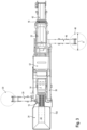
- the rock processing device 12 has the following based on the larger representation of Figure 2 described device components:
- the rock processing device 12 comprises a control device 60, for example in the form of an electronic data processing system with integrated circuits, which controls the operation of device components.
- the control device 60 can, for example, either directly control drives of device components or control actuators, which in turn can move components.
- the control device 60 is connected to a data storage device 62 for signal transmission for data exchange and is connected to an input device 64 for inputting information.
- Information can be input to the input device 64 via the input device 64, for example a touchscreen, a tablet computer, a keyboard and the like, and stored by the latter in the data storage device 62.
- control device 60 is connected to an output device 66 for signal transmission in order to output information.
- the rock processing device 12 also has various sensors for obtaining information about its operating state, which are connected to the control device 60 for signal transmission and thus, in the example shown, indirectly to the data storage device 62. For the sake of clarity, the sensors are only shown in Figure 2 shown.
- a camera 70 is arranged on a support frame 68, which camera takes pictures of the material feed device 22 with the material buffer 24 and transmits them to the control device 60 for image processing. With the help of the camera 70 and by image processing of the images of the material buffer 24 and the material feed device 22 taken by it, the control device determines a local filling level of the material buffer 24 using data relationships stored in the data memory 22.
- the drive (not shown) of the trough conveyor 26 detects its vibration amplitude and vibration frequency and transmits them to the control device 60, which uses this information to determine a conveying speed of the trough conveyor 26 and, taking into account the local filling level of the material buffer 24, a conveying capacity of the trough conveyor 26 to the impact crusher 14.
- control device 60 can recognize a grain size distribution in the material M in the material buffer 24 and even the type of material from the image information of the camera 70.
- An upper impact rocker 72 and a lower impact rocker 74 are arranged in the impact crusher 14 in a manner known per se, the rotational position of the upper impact rocker 72 being detected by a rotational position sensor 76 and the rotational position of the lower impact rocker 74 being detected by a rotational position sensor 78 and transmitted to the control device 60.
- the control device 60 can also use the rotational position sensors 76 and 78 to determine a crushing gap width of an upper crushing gap on the upper impact rocker 72 and a crushing gap width of a lower crushing gap on the lower impact rocker 74.
- a speed sensor 80 determines the speed of the crushing rotor of the impact crusher 14 and transmits it to the control device 60.
- Wear sensors can be provided on components that are particularly subject to wear, such as impact bars, impact rockers, impact plates and impact beams, which register the progress of wear, usually in wear stages, and transmit it to the control device 60.
- a wear sensor arrangement 82 is only shown on the lower impact rocker 74 for better clarity.
- a first belt scale 84 is arranged in the first conveyor device 32, which measures the weight or mass of the material of the useful grain fraction 28 transported above it on the first conveyor device 32.
- the speed sensor 86 in a deflection roller of the conveyor belt of the first conveyor device 32 can be used to Control device 60 can determine a conveying speed of the first conveying device 32 and, in conjunction with the detection signals of the first belt scale 84, can determine a conveying capacity of the first conveying device 32.
- a second belt scale 88 is arranged in the fine grain discharge conveyor device 42 and detects the mass or weight of the fine grain of the fine grain fraction 38 moved above it on the belt of the fine grain discharge conveyor device 42.
- a conveying speed of the fine grain discharge conveyor device 42 and, in conjunction with the detection signals of the second belt scale 88, a conveying capacity of the fine grain discharge conveyor device 42 can be determined by the control device 60 using the speed sensor 90 in a deflection roller of the conveyor belt of the fine grain discharge conveyor device 42.
- a third belt scale 92 is arranged in the oversize grain conveyor device 36 and determines the weight or mass of the oversize grain of the oversize grain fraction 34 conveyed above it on the oversize grain conveyor device 36.
- a speed sensor 94 of a deflection roller of the conveyor belt of the oversize grain conveyor device 36 determines the conveying speed of the oversize grain conveyor device 36 and transmits this to the control device 60, which can determine a conveying capacity of the oversize grain conveyor device in conjunction with the detection signals of the third belt scale 92.
- a first stockpile sensor 96 is arranged on the discharge-side longitudinal end of the fine grain discharge conveyor device 42, which as a camera takes pictures of the fine grain stockpile 44 and transmits them as image information to a control device 60, which recognizes contours of the fine grain stockpile 48 through image processing and, based on the known image data of the camera of the first stockpile sensor 96, determines a shape and from this a volume of the fine grain stockpile 48 based on the recognized contours.
- the control device 60 can, without excessive error, assume an ideal conical shape of the fine grain stockpile 48 to simplify its information determination and determine the volume of an ideal cone that approximates the real fine grain stockpile 48. It can thus be sufficient for a stockpile sensor to determine the diameter D of the base area of a stockpile and the height h of the stockpile, as in the Figures 2 and 3 as shown using the example of Halde 48.
- a second stockpile sensor 98 which can be used alternatively or additionally.
- the second stockpile sensor 98 comprises a flight-capable drone as a carrier, the movement of which can be remotely controlled by the control device 60.
- the second stockpile sensor 98 also serves to determine at least one height of the fine grain stockpile 48, but preferably to determine its shape and thus its volume.
- An advantage of using a drone or a sensor installed at an elevated location, such as on a high mast or stand, is that one sensor can detect more than one stockpile in terms of its height and/or shape and/or volume.
- a number of sensors which is less than the total number of stockpiles to be detected on the rock processing device 12, on a rock processing plant or on the construction site 10 can be sufficient to detect each of the stockpiles to be detected.
- exactly one sensor is then sufficient to actually detect all of the stockpiles to be detected.
- Each discharge conveyor device creating a stockpile preferably has at least one stockpile sensor or cooperates with a stockpile sensor.
- the remaining discharge conveyor devices such as the medium grain discharge conveyor device 46 and a under grain discharge conveyor device 29, preferably also have a belt scale and a speed sensor for detecting the amount of material transported on the respective conveyor device, the conveying speed and thus the conveying capacity.
- the output device 66 is explained in more detail below:
- the output device 66 may have, for example on the support frame 68, a projection device 100 to project a marking within the Figure 2 shown and identical to the feed opening of the material buffer 24.
- the total feed area 102 is selected such that a grain falling along the direction of gravity reaches the material feed device 22 without falling directly onto the pre-screen 16.
- the output device 66 further comprises a transmitting/receiving unit 104, which transmits data by radio in a suitable data protocol to a receiving device set up for communication with it, such as the receiving device 106 in the Figures 4 and 5 , transmit and receive from it.
- a transmitting/receiving unit 104 which transmits data by radio in a suitable data protocol to a receiving device set up for communication with it, such as the receiving device 106 in the Figures 4 and 5 , transmit and receive from it.
- the output device 66 also has a first display device 108, for example in the form of a monitor, for externally perceptible display of time information for the next material feed into the material feed device 22.
- the output device 66 in the embodiment shown has a second display device 110, for example again a monitor, for externally perceptible display of time information and location information for the next stockpile removal.
- the display device 110 not only shows time information about when the next stockpile removal should begin, but also location information about which of the stockpiles should be removed at the specified time and, if applicable, by what amount the specified stockpile should be removed.
- the excavator 20 also includes a transmitting/receiving device 112 with data storage, which is set up to communicate with the transmitting/receiving unit 104 of the rock processing device 12.
- the transmitting/receiving device 112 can thus transmit relevant data about the excavator 20 to the transmitting/receiving unit 104, such as the capacity of its bucket 21 as its loading tool and/or its current GPS data.
- the wheel loader 58 comprises a transmitting/receiving device 114 with data storage, which is set up for communication with the transmitting/receiving unit 104 of the rock processing device 12.
- the transmitting/receiving device 112 can thus transmit relevant data about the wheel loader 58 to the transmitting/receiving unit 104, such as the capacity of its bucket 59 as its mining tool and/or its current GPS data.
- the data storage 62 contains several data relationships that link operating and/or material parameters. These data relationships can be tested in advance by test operations with targeted Parameter variations are determined and stored in the data memory 62.
- the use of artificial intelligence methods to determine causal relationships between operating and/or material parameters is particularly helpful for more complex multidimensional data relationships.
- the data relationships determined in this way can be continuously verified, refined and/or corrected during further operation of the rock processing device 12, again preferably using artificial intelligence methods.
- the discontinuous material feed naturally leads to a surge-like material feed, with a given surge of material being limited by the size of the bucket 21 of the excavator 20.
- the time intervals between two discontinuous material feeds are unpredictable and fluctuate.
- control device 60 uses detection signals from one or more of the aforementioned sensors to determine time information which represents an execution time of a future, in particular next, material feed into the material feed device 22.
- the control device 60 preferably uses the determined locally differentiated filling level of the material buffer 24 and takes into account the conveying performance of the channel conveyor 26 and, for example, the undersize conveying device 29 and the first conveying device 32.
- a balance analysis of the material flows of the channel conveyor 26 into the impact crusher 14 and of the undersize conveying device 29 and the first conveying device 32 away from the impact crusher 14 shows whether the filling level of the impact crusher 14 changes over time, for example increases or decreases, and thus provides a measure of whether the conveying performance of the channel conveyor 26 can be maintained or must be changed.
- the conveying performance of the channel conveyor 26 is, however, decisive for how quickly the material buffer 24 should be emptied and reloaded with material.
- a sensor can also be provided directly on the rock processing device 12 for detecting the filling level of the impact crusher 14.
- control device 60 takes into account the amount of oversized grain returned, since the oversized grain fraction 34 also contributes to the filling level of the material buffer 24.
- a predefined data context stored in the data memory 62 can link the detection signals of the camera 70, the first belt scale 84, the speed sensor 86, a belt scale and a speed sensor on the undersize grain discharge conveyor, the belt scale 92 and the speed sensor 94 of the oversize grain conveyor 36 as well as the size of the bucket 21 of the excavator 20, possibly taking into account the distance of the excavator 20 from the material feed device 22, as input variables with time information as an output variable, which indicates when the next material feed into the material feed device 22 should take place.
- This time information can be displayed on the first output device 108 in a suitable form, for example as an hourglass, waiting time bar, time countdown or analog clock display, perceptibly for everyone within sight of the rock processing device 20.
- the time information can also be sent by the transmitting/receiving unit 104 to a mobile receiving device 106, which is available to the operator of the excavator 20.
- the mobile receiving device 106 can be a portable mobile device, such as a mobile phone, a tablet computer and the like, or can be permanently installed in the excavator 20 as part of its control device and remain in the excavator 20.
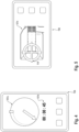
- FIG. 4 By way of example, a representation of time information on the receiving device 106 is shown both graphically in the upper half by pointer representation 107a and alphanumerically in the lower half by time countdown 107b. In the case shown, the next material delivery is desired in 00 minutes and 45 seconds.
- control device 60 can successively control the discontinuous material feed and, despite the discontinuity of the material feed, ensure the best possible material flow in the rock processing device 12.
- control device 60 is also able, based on a further data context stored in the data memory 62, to control the next material feed not only in terms of time but also in terms of location within the overall feed area 102 of the material buffer 24 or the material feed device 22 or to provide location information about a preferred material feed location within the overall feed area 102.
- control device 60 can convey a loading of the material buffer 24 that is as advantageous as possible over the entire operating time of the rock processing device 12 for the respective design of the material feeding device 22 and the rock processing device 12 as a whole, which can be identified parametrically in the data memory 62 for use by the control device 60.
- control device 60 can thus output location information to the operator of the excavator 20 as to where the next material loading should take place within the overall loading area 102.
- the output device 66 can output this location information through the projection device 100 for everyone to see, in that the projection device 100 projects a marking within the overall feed area 102 or within the material buffer 24 at the location at which the next material feed should take place.
- the location information can be output to the machine operator of the excavator 20 via the receiving device 106.
- Figure 5 shows an embodiment of a location information output.
- the receiving device 106 shows a schematic representation 197c of the material buffer 24 with the total feed area 102 and marks the desired feed location within the total feed area 102 for the next material feed using a suitable marking 116.
- a discharge height or a discharge height range that is preferably to be maintained can also be specified quantitatively, for example in meters and/or centimeters, or qualitatively, for example by specifying qualitative discharge height parameters such as "low", "medium” and "high".
- the additional height information is easy to implement, particularly when transmitting the location information to an excavator control system, which may be partially automatic.
- the control device 60 can, taking into account material parameters such as the type of material fed in, grain size and grain size distribution, and possibly the resulting bulk density, detect an increase in the stockpiles 30, 44 and 48 produced by the rock processing device 12 and, above all, detect a change or growth rate of the respective stockpile and, using a previously generated and stored data context, determine mining time information as to when a certain stockpile should be mined by the wheel loader 58. This can prevent the stockpile from growing too much and blocking a discharge via the discharge conveyor device producing the respective stockpile.
- control device can determine further degradation information, which indicates the extent to which degradation is to take place, taking into account material parameters such as grain size and grain size distribution as well as density, using a data context determined for this purpose.
- the output device 66 also outputs further mining information which identifies the heap affected by the mining time information.
- the control device 60 can display the mining time information and the other mining information on the second display device 110 so that it is visible to everyone in the field of vision of the rock processing device 12. Additionally or alternatively, the output device 66 can transmit the information on the next dump mining to the receiving device 106 via the transmitting/receiving unit 104, where it is output to the machine operator of the wheel loader 58 in graphic and/or alphanumeric form.
- control device 60 can control operating parameters of the rock processing device 12 from detection signals from suitable sensors so that, in the embodiment shown, a predetermined desired ratio of fine grain quantity to medium grain quantity is obtained.
- control device 60 can control the rock processing device 12 on the basis of appropriately prepared data relationships so that its energy consumption per unit of quantity of processed mineral material reaches or is reduced to at least a local minimum.
- control device 60 can control the rock processing device 12 using appropriately prepared data relationships so that an amount of oversize grain that is advantageous for the respective crushing process is returned so that there is sufficient support grain in the crushing gap or in the crushing gaps due to pre-crushed oversize grain.
- an operation aimed at minimizing or eliminating the amount of oversize is not necessarily the most economical operation of the rock processing device 12 due to the beneficial effects of oversize as a support grain in the crushing gap.
- a very small amount of oversize often means an excessive amount of overly finely crushed material, which is generally not desired. If the amount of recycled material decreases, the quality of the final product often also decreases because it then contains less multiply crushed material.
- control device 60 can also aim to operate the rock processing device 12 on the basis of several target variables or one target variable with further specified boundary conditions based on the data relationships available to it and determined in advance by test operations with targeted parameter variation, such as the production of valuable grain with different grain sizes in a predetermined quantity ratio with the lowest possible energy consumption and with the most advantageous possible amount of returned oversize grain.
- control device 60 can change the conveying speed of one or more conveying devices, can change the crushing gap width, in particular of the upper and/or lower crushing gap, can change the rotor speed, can control the material feed into the material feed device 22 locally and temporally, etc.
- the input variables used for operational optimization can be the size and/or height and/or growth of valuable grain stockpiles, in this case, for example, valuable grain stockpiles 44 and 48, the size and/or height and/or growth of the stockpile of the undersize fraction 30, the amount of oversize grain returned, the fed-in grain size and fed-in grain size distribution, which can be determined primarily via the material parameters entered via the input device 64.
- the entered material parameters can include at least one material parameter from the type of material, moisture level, hardness, density, breakability, abrasiveness, proportion of foreign matter in the fed-in and/or processed material, etc., the grain size and grain size distribution in the individual discharge conveyor devices. This list is not exhaustive.
- the grain size and grain size distribution, and possibly also the grain shape can be determined by cameras with downstream image processing.
- the grain size and the grain size distribution in a discharge conveyor can be additionally or alternatively determined by the allocation of one of the respective discharge conveyors in the material flow upstream screening device. Additionally or alternatively, the desired target quantity of a respective end product can serve as an input variable for operational optimization.
- control device 60 By applying artificial intelligence methods, the control device 60, if desired with the involvement of powerful external data processing devices, can continuously improve the accuracy of the stored data relationships through its daily operation and the data and knowledge collected during it.
- the rock processing device 12 can thus not only optimize its own operation, but can essentially gradually take over the organization of the entire construction site in the immediate vicinity of the rock processing device 12.
Landscapes
- Engineering & Computer Science (AREA)
- Food Science & Technology (AREA)
- Disintegrating Or Milling (AREA)
Claims (10)
- Dispositif de traitement de roches (12) pour le broyage ou/et le triage en fonction de la taille de matériaux minéraux granuleux (M), le dispositif de traitement de roches (12) comprenant comme composants de dispositif :- un dispositif d'alimentation en matériau (22) avec un tampon de matériau (24) pour le chargement du matériau de départ (M) à traiter,- au moins une unité de travail composée de+ au moins un dispositif de concassage (14) et+ au moins un dispositif de criblage (16, 18),- au moins un dispositif de transport (26, 32) pour le transport de matériau entre deux composants du dispositif,- un dispositif de commande (60) pour commander les composants du dispositif de traitement de la roche (12),- au moins un capteur (72, 74, 76, 78, 80, 82, 84, 86, 88, 90, 92, 94, 96, 98) pour détecter au moins un paramètre de fonctionnement, le capteur (72, 74, 76, 78, 80, 82, 84, 86, 88, 90, 92, 94, 96, 98) étant relié au dispositif de commande (60) par transmission de signal pour transmettre un signal de détection représentant le au moins un paramètre de fonctionnement détecté,- au moins un dispositif de sortie (66) pour la sortie d'informations, le dispositif de sortie (66) étant connecté au dispositif de commande (60) pour la transmission d'informations par transmission de signal,caractérisé en ce que le dispositif de commande (60) est conçu pour déterminer, dans un fonctionnement avec alimentation en matériaux discontinue du matériau de départ (M) à traiter, sur la base dudit au moins un signal de détection, une information de temps qui représente un temps d'exécution d'une alimentation en matériaux future dans le dispositif d'alimentation en matériaux (22), le dispositif de sortie (66) étant conçu pour délivrer l'information de temps déterminée.
- Dispositif de traitement des roches (12) selon la revendication 1,
caractérisé en ce que le dispositif de traitement de granulats (12) est conçu pour déterminer, dans le fonctionnement avec une alimentation en matériaux discontinue, pour au moins deux futures alimentations en matériaux successives, respectivement un temps d'exécution individuel en tant qu'information temporelle et pour l'émettre respectivement au moyen du dispositif de sortie (66). - Dispositif de traitement des roches (12) selon la revendication 1 ou 2, caractérisé en ce que le dispositif de traitement de roche (12) comprend un dispositif d'entrée (64) pour l'entrée d'informations, le dispositif d'entrée (64) étant connecté au dispositif de commande (60) pour la transmission d'informations, le dispositif de commande (60) étant conçu pour déterminer les informations de temps sur la base d'au moins un signal de détection et d'une information entrée dans le dispositif d'entrée (64) dans le fonctionnement avec une alimentation en matériau discontinue.
- Dispositif de traitement des roches (12) selon l'une des revendications précédentes,
caractérisé en ce que ledit au moins un capteur est adapté pour détecter et transmettre au dispositif de commande (60) au moins l'un des paramètres de fonctionnement suivants :- degré de remplissage du tampon de matériau (24),- degré de remplissage d'au moins un dispositif de transport (26, 32),- vitesse de transport d'au moins un dispositif de transport (26, 32),- degré de remplissage d'au moins une unité de travail (14, 16, 18),- forme des grains ou/et taille des grains ou/et répartition de la taille des grains du matériau chargé ou/et transporté,- type de matériau chargé ou/et transporté,- humidité du matériau chargé,- densité du matériau chargé,- dureté du matériau chargé,- friabilité du matériau chargé,- abrasivité du matériau abandonné,- état de la matière chargée,- quantité d'excédents de grains recyclés,- quantité de matériau à charger ou chargé,- charge de travail d'au moins un dispositif d'entraînement,- charge de travail d'au moins une unité de travail (14, 16, 18),- vitesse de travail d'au moins une unité de travail (14, 16, 18),- dimension d'une fente de concassage du dispositif de concassage (14)- dimension des mailles d'un tamis du dispositif de criblage (16),- taille d'un outil de chargement (21) d'un dispositif de chargement (20) chargeant le tampon de matériau (24) de manière discontinue.- quantité ou proportion de matériau étranger, en particulier de matériau non friable. - Dispositif de traitement de roches (12) selon la revendication 3 ou selon les revendications 3 et 4,
caractérisé en ce que le dispositif de commande (60) est conçu pour déterminer, dans le fonctionnement avec alimentation en matériaux discontinue, l'information de temps en tenant compte d'au moins une des informations suivantes entrées dans le dispositif d'entrée (64) :- degré de remplissage théorique du tampon de matériau,- degré de remplissage de consigne d'au moins un dispositif de transport,- vitesse de transport de consigne d'au moins un dispositif de transport,- degré de remplissage de consigne du dispositif de concassage,- dimension de consigne d'une fente de concassage du dispositif de concassage,- charge de fonctionnement de consigne d'au moins un dispositif d'entraînement,- charge de fonctionnement de consigne du dispositif de concassage,- granulométrie de consigne ou/et répartition granulométrique de consigne du matériau alimenté ou/et transporté,- quantité de consigne de grains excédentaires recyclés,- largeur de maille théorique d'un tamis du dispositif de criblage,- type de matériau chargé ou/et transporté,- taille d'un outil de chargement d'un dispositif de chargement chargeant le tampon de matériau de manière discontinue. - Dispositif de traitement des roches (12) selon l'une des revendications précédentes,
caractérisé en ce que le dispositif de sortie (66) est conçu de manière indépendante du récepteur pour la sortie d'informations dans une zone spatiale entourant au moins partiellement le dispositif de traitement de roches (12) ou/et adjacente au dispositif de traitement de roches (12). - Dispositif de traitement des roches (12) selon l'une des revendications précédentes,
caractérisé en ce que le dispositif de traitement de roche (12) comprend un dispositif de réception (106) séparé d'un corps de machine du dispositif de traitement de roche (12), mobile par rapport au corps de machine et pouvant être séparé du corps de machine, le dispositif de sortie (66) étant adapté pour transmettre l'information de temps au dispositif de réception (106) et pour la délivrer ainsi. - Dispositif de traitement de roches (12) selon la revendication 7,
caractérisé en ce que le dispositif de réception (106) est un dispositif de réception portable (106). - Combinaison de machines composée d'un dispositif de traitement de roches (12) selon la revendication 7 ou 8 et d'un dispositif de chargement (20) chargeant de manière discontinue le tampon de matériau (24) du dispositif de traitement de roches (12),
caractérisé en ce que le dispositif de réception (106) est disposé dans le dispositif de chargement (20). - Combinaison de machines selon la revendication 9,
caractérisé en ce que le dispositif de réception (106) délivre l'information de temps de manière graphique ou/et acoustique à un conducteur de machine du dispositif de chargement (20) ou/et commande un composant de fonctionnement (21) du dispositif de chargement (20) qui est important pour le transport.
Applications Claiming Priority (1)
| Application Number | Priority Date | Filing Date | Title |
|---|---|---|---|
| DE102022118032.8A DE102022118032B3 (de) | 2022-07-19 | 2022-07-19 | Mobile Gesteinsverarbeitungsvorrichtung mit verbesserter Planung einer diskontinuierlichen Materialaufgabe |
Publications (3)
| Publication Number | Publication Date |
|---|---|
| EP4309795A1 EP4309795A1 (fr) | 2024-01-24 |
| EP4309795C0 EP4309795C0 (fr) | 2024-12-18 |
| EP4309795B1 true EP4309795B1 (fr) | 2024-12-18 |
Family
ID=87280943
Family Applications (1)
| Application Number | Title | Priority Date | Filing Date |
|---|---|---|---|
| EP23185111.4A Active EP4309795B1 (fr) | 2022-07-19 | 2023-07-12 | Dispositif mobile de traitement de roche avec planification améliorée d'une tâche de matériau discontinue |
Country Status (4)
| Country | Link |
|---|---|
| US (1) | US12508602B2 (fr) |
| EP (1) | EP4309795B1 (fr) |
| CN (1) | CN117414902A (fr) |
| DE (1) | DE102022118032B3 (fr) |
Cited By (1)
| Publication number | Priority date | Publication date | Assignee | Title |
|---|---|---|---|---|
| EP4789767A1 (fr) | 2025-02-11 | 2026-08-12 | Rubble Master HMH GmbH | Procédé de détection de ralenti d'une unité de traitement de matériau |
Families Citing this family (1)
| Publication number | Priority date | Publication date | Assignee | Title |
|---|---|---|---|---|
| DE102023130685A1 (de) | 2023-11-06 | 2025-05-08 | Kleemann Gmbh | Verfahren zur Authentifizierung einer drahtlosen Fernbedienung als temporärer Teil einer Steuereinrichtung einer Gesteinsveränderungsvorrichtung |
Family Cites Families (21)
| Publication number | Priority date | Publication date | Assignee | Title |
|---|---|---|---|---|
| US2632584A (en) * | 1953-03-24 | Feeder for granular bulk material | ||
| US1487934A (en) * | 1920-08-27 | 1924-03-25 | W C Meadows Mill Co | Agitator |
| US4281800A (en) | 1979-11-02 | 1981-08-04 | Allis-Chalmers Corporation | Operation of associated crushing plant and mill |
| US4909449A (en) | 1989-03-10 | 1990-03-20 | Etheridge Johnny E | Primary crushing stage control system |
| NZ518111A (en) | 2002-06-09 | 2004-09-24 | Metso Minerals Matamata Ltd | Control system for a vertical shaft impactor (VSI) rock crusher to control the cascade ratio |
| JP2004322075A (ja) * | 2003-04-09 | 2004-11-18 | Komatsu Ltd | 破砕機の負荷表示装置 |
| BRPI0721583B1 (pt) * | 2007-04-18 | 2019-04-02 | Metso Minerals Inc. | Interface de usuário de equipamento de processamento de mineral ou rejeito |
| GB0707761D0 (en) * | 2007-04-21 | 2007-05-30 | Finlay Hydrascreens Ltd | Crushing machines |
| AT506278B1 (de) * | 2007-12-21 | 2010-03-15 | Wittmann Kunststoffgeraete Gmb | Verfahren zur ermittlung der befüllzeit |
| FI122462B (fi) | 2008-06-27 | 2012-01-31 | Metso Minerals Inc | Menetelmä ja laitteisto murskausprosessin säätöön |
| FI128934B (fi) * | 2012-06-08 | 2021-03-31 | Metso Minerals Inc | Menetelmä mineraalimateriaalin prosessointilaitoksen ohjaamiseksi ja mineraalimateriaalin prosessointilaitos |
| DE102017124958A1 (de) | 2017-10-25 | 2019-04-25 | Kleemann Gmbh | Verfahren zum lastabhängigen Betrieb einer Materialzerkleinerungsanlage |
| DE102018106177A1 (de) | 2018-03-16 | 2019-09-19 | Kleemann Gmbh | Aufbereitungsanlage |
| EP3590612A1 (fr) | 2018-07-05 | 2020-01-08 | Siemens Aktiengesellschaft | Procédé et dispositif de gestion des unités d'un produit en vrac ainsi que programme informatique |
| DE102019126978A1 (de) | 2019-10-08 | 2021-04-08 | Kleemann Gmbh | Gesteinsverarbeitungsmaschine mit verbesserter Bedienkonsole |
| US20210325899A1 (en) | 2020-04-21 | 2021-10-21 | Caterpillar Inc. | Systems and methods for controlling a discharge rate of a hauling machine |
| DE102020003966B4 (de) | 2020-07-01 | 2022-03-24 | Keestrack N.V. | Mobile Zerkleinerungsanlage und Verfahren zum Herstellen eines gebrochenen, mineralischen Endkornproduktes |
| CN112317103A (zh) * | 2020-09-21 | 2021-02-05 | 韶关祺瑞环保设备有限公司 | 一种移动反击式破碎站 |
| DE102020125132B4 (de) * | 2020-09-25 | 2024-10-31 | Kleemann Gmbh | Verfahren zur Ermittlung des Verschleißes einer Prallschwinge eines Prallbrechers |
| GB2609081C (en) * | 2022-05-23 | 2023-08-16 | Portafill International Ltd | Mobile aggregate processing plant |
| DE102022118039B3 (de) * | 2022-07-19 | 2023-08-10 | Kleemann Gmbh | Gesteinsverarbeitungsvorrichtung mit verbesserter Abbauplanung der Halde des Verarbeitungsergebnisses |
-
2022
- 2022-07-19 DE DE102022118032.8A patent/DE102022118032B3/de active Active
-
2023
- 2023-07-12 EP EP23185111.4A patent/EP4309795B1/fr active Active
- 2023-07-17 US US18/353,332 patent/US12508602B2/en active Active
- 2023-07-17 CN CN202310871253.5A patent/CN117414902A/zh active Pending
Cited By (1)
| Publication number | Priority date | Publication date | Assignee | Title |
|---|---|---|---|---|
| EP4789767A1 (fr) | 2025-02-11 | 2026-08-12 | Rubble Master HMH GmbH | Procédé de détection de ralenti d'une unité de traitement de matériau |
Also Published As
| Publication number | Publication date |
|---|---|
| EP4309795C0 (fr) | 2024-12-18 |
| DE102022118032B3 (de) | 2023-08-10 |
| US20240024889A1 (en) | 2024-01-25 |
| CN117414902A (zh) | 2024-01-19 |
| EP4309795A1 (fr) | 2024-01-24 |
| US12508602B2 (en) | 2025-12-30 |
Similar Documents
| Publication | Publication Date | Title |
|---|---|---|
| DE102022118039B3 (de) | Gesteinsverarbeitungsvorrichtung mit verbesserter Abbauplanung der Halde des Verarbeitungsergebnisses | |
| DE102022118042B3 (de) | Gesteinsverarbeitungsanlage mit wenigstens zwei Wertkorn-Sieblinien und von den Sieblinienausträgen abhängiger automatisierter Betriebsführung | |
| EP4309796B1 (fr) | Dispositif de traitement de roches à planification améliorée de l'emplacement d'une tâche de matériau à l'intérieur d'un tampon de matériau | |
| DE102021117537B3 (de) | Gesteinsverarbeitungsmaschine mit Bilderfassung und mit Bildverarbeitung durch ein neuronales Netzwerk | |
| EP4309795A1 (fr) | Dispositif mobile de traitement de roche avec planification améliorée d'une tâche de matériau discontinue | |
| DE102020101775A1 (de) | System und verfahren zur steuerung der meldefrequenz | |
| EP3702532B1 (fr) | Finisseur et son procédé de fonctionnement | |
| EP2823106B1 (fr) | Système et procédé pour l'exploitation d'un terril | |
| DE102011114183A1 (de) | Verfahren zur Steuerung eines Beladungsvorgangs eines Transportfahrzeugs mit Fräsgut, Vorrichtung zur Durchführung eines solchen Verfahrens und Fräsvorrichtung | |
| WO2016150918A1 (fr) | Système et procédé d'exploitation d'un dépôt de matériau | |
| EP4201528A1 (fr) | Procédé de réglage d'un état de fonctionnement d'au moins une installation mobile de traitement de minéraux | |
| DE102012016332A1 (de) | Verfahren zur Steuerung und/oder Regelung eines Volumenstromes, eines Schüttgutes oder von Schüttgütern, insbesondere von mineralischen Schüttgütern, von Abfallstoffen, von Rohstoffen oder von Materialen bzw. Vorrichtung zur Durchführung des zuvor genannten Verfahrens | |
| EP4403262B1 (fr) | Machine de traitement de roches dotée d'une évaluation d'usure et d'une évaluation qualitative de l'évaluation d'usure | |
| EP2811072B1 (fr) | Machine de nettoyage de voie ferrée dotée d'un traitement de couche de protection de plate-forme | |
| DE102022105345A1 (de) | Verfahren zur Steuerung und/oder Regelung der Zuförderung zu bearbeitenden Materials zu einer Brech- und/oder Siebanlage einer Materialverarbeitungseinrichtung | |
| DE102022128234A1 (de) | Pflastermaterialentmischungserfassung und -überwachung | |
| EP2428612A1 (fr) | Machine de nettoyage de voie ferrée dotée d'un traitement de couche de protection de plate-forme | |
| DE19727348A1 (de) | Verfahren zur Regelung von Stein-Zerkleinerungsanlagen unter Einsatz von Prallbrechern o. dgl. | |
| DE102021134144A1 (de) | Verfahren zur Einstellung eines Betriebszustands zumindest einer mobilen Mineral-Bearbeitungsanlage | |
| DE102024133450A1 (de) | Verfahren zur Kommunikation zwischen einer Materialverarbeitungseinrichtung und einem Mobilgerät und Verfahren zur Übermittlung eines Anlagenzustands und/oder einer Meldung betreffend einen Anlagenzustand einer Materialverarbeitungseinrichtung an ein Mobilgerät | |
| DE102024133449A1 (de) | Verfahren zur Kommunikation zwischen einer Materialverarbeitungseinrichtung und einem Mobilgerät und Verfahren zur Übermittlung eines Anlagenzustands und/oder einer Meldung betreffend einen Anlagenzustand einer Materialverarbeitungseinrichtung an ein Mobilgerät | |
| EP1679131A1 (fr) | Machine pour la préparation de matériau excavé | |
| WO2020038992A1 (fr) | Procédé et dispositif pour faire fonctionner une installation de concassage | |
| DE10337024A1 (de) | Verfahren zum automatisierten Betreiben eines Kohlelagers |
Legal Events
| Date | Code | Title | Description |
|---|---|---|---|
| PUAI | Public reference made under article 153(3) epc to a published international application that has entered the european phase |
Free format text: ORIGINAL CODE: 0009012 |
|
| STAA | Information on the status of an ep patent application or granted ep patent |
Free format text: STATUS: REQUEST FOR EXAMINATION WAS MADE |
|
| 17P | Request for examination filed |
Effective date: 20230712 |
|
| AK | Designated contracting states |
Kind code of ref document: A1 Designated state(s): AL AT BE BG CH CY CZ DE DK EE ES FI FR GB GR HR HU IE IS IT LI LT LU LV MC ME MK MT NL NO PL PT RO RS SE SI SK SM TR |
|
| GRAP | Despatch of communication of intention to grant a patent |
Free format text: ORIGINAL CODE: EPIDOSNIGR1 |
|
| STAA | Information on the status of an ep patent application or granted ep patent |
Free format text: STATUS: GRANT OF PATENT IS INTENDED |
|
| INTG | Intention to grant announced |
Effective date: 20240627 |
|
| GRAJ | Information related to disapproval of communication of intention to grant by the applicant or resumption of examination proceedings by the epo deleted |
Free format text: ORIGINAL CODE: EPIDOSDIGR1 |
|
| STAA | Information on the status of an ep patent application or granted ep patent |
Free format text: STATUS: REQUEST FOR EXAMINATION WAS MADE |
|
| INTC | Intention to grant announced (deleted) | ||
| GRAP | Despatch of communication of intention to grant a patent |
Free format text: ORIGINAL CODE: EPIDOSNIGR1 |
|
| STAA | Information on the status of an ep patent application or granted ep patent |
Free format text: STATUS: GRANT OF PATENT IS INTENDED |
|
| INTG | Intention to grant announced |
Effective date: 20241004 |
|
| GRAS | Grant fee paid |
Free format text: ORIGINAL CODE: EPIDOSNIGR3 |
|
| GRAA | (expected) grant |
Free format text: ORIGINAL CODE: 0009210 |
|
| STAA | Information on the status of an ep patent application or granted ep patent |
Free format text: STATUS: THE PATENT HAS BEEN GRANTED |
|
| AK | Designated contracting states |
Kind code of ref document: B1 Designated state(s): AL AT BE BG CH CY CZ DE DK EE ES FI FR GB GR HR HU IE IS IT LI LT LU LV MC ME MK MT NL NO PL PT RO RS SE SI SK SM TR |
|
| REG | Reference to a national code |
Ref country code: CH Ref legal event code: EP |
|
| REG | Reference to a national code |
Ref country code: DE Ref legal event code: R096 Ref document number: 502023000398 Country of ref document: DE |
|
| REG | Reference to a national code |
Ref country code: IE Ref legal event code: FG4D Free format text: LANGUAGE OF EP DOCUMENT: GERMAN |
|
| U01 | Request for unitary effect filed |
Effective date: 20250102 |
|
| U07 | Unitary effect registered |
Designated state(s): AT BE BG DE DK EE FI FR IT LT LU LV MT NL PT RO SE SI Effective date: 20250114 |
|
| PG25 | Lapsed in a contracting state [announced via postgrant information from national office to epo] |
Ref country code: HR Free format text: LAPSE BECAUSE OF FAILURE TO SUBMIT A TRANSLATION OF THE DESCRIPTION OR TO PAY THE FEE WITHIN THE PRESCRIBED TIME-LIMIT Effective date: 20241218 |
|
| PG25 | Lapsed in a contracting state [announced via postgrant information from national office to epo] |
Ref country code: NO Free format text: LAPSE BECAUSE OF FAILURE TO SUBMIT A TRANSLATION OF THE DESCRIPTION OR TO PAY THE FEE WITHIN THE PRESCRIBED TIME-LIMIT Effective date: 20250318 |
|
| PG25 | Lapsed in a contracting state [announced via postgrant information from national office to epo] |
Ref country code: GR Free format text: LAPSE BECAUSE OF FAILURE TO SUBMIT A TRANSLATION OF THE DESCRIPTION OR TO PAY THE FEE WITHIN THE PRESCRIBED TIME-LIMIT Effective date: 20250319 |
|
| PG25 | Lapsed in a contracting state [announced via postgrant information from national office to epo] |
Ref country code: RS Free format text: LAPSE BECAUSE OF FAILURE TO SUBMIT A TRANSLATION OF THE DESCRIPTION OR TO PAY THE FEE WITHIN THE PRESCRIBED TIME-LIMIT Effective date: 20250318 |
|
| PG25 | Lapsed in a contracting state [announced via postgrant information from national office to epo] |
Ref country code: SM Free format text: LAPSE BECAUSE OF FAILURE TO SUBMIT A TRANSLATION OF THE DESCRIPTION OR TO PAY THE FEE WITHIN THE PRESCRIBED TIME-LIMIT Effective date: 20241218 |
|
| PG25 | Lapsed in a contracting state [announced via postgrant information from national office to epo] |
Ref country code: PL Free format text: LAPSE BECAUSE OF FAILURE TO SUBMIT A TRANSLATION OF THE DESCRIPTION OR TO PAY THE FEE WITHIN THE PRESCRIBED TIME-LIMIT Effective date: 20241218 |
|
| PG25 | Lapsed in a contracting state [announced via postgrant information from national office to epo] |
Ref country code: ES Free format text: LAPSE BECAUSE OF FAILURE TO SUBMIT A TRANSLATION OF THE DESCRIPTION OR TO PAY THE FEE WITHIN THE PRESCRIBED TIME-LIMIT Effective date: 20241218 |
|
| PG25 | Lapsed in a contracting state [announced via postgrant information from national office to epo] |
Ref country code: IS Free format text: LAPSE BECAUSE OF FAILURE TO SUBMIT A TRANSLATION OF THE DESCRIPTION OR TO PAY THE FEE WITHIN THE PRESCRIBED TIME-LIMIT Effective date: 20250418 |
|
| PG25 | Lapsed in a contracting state [announced via postgrant information from national office to epo] |
Ref country code: SK Free format text: LAPSE BECAUSE OF FAILURE TO SUBMIT A TRANSLATION OF THE DESCRIPTION OR TO PAY THE FEE WITHIN THE PRESCRIBED TIME-LIMIT Effective date: 20241218 |
|
| PG25 | Lapsed in a contracting state [announced via postgrant information from national office to epo] |
Ref country code: CZ Free format text: LAPSE BECAUSE OF FAILURE TO SUBMIT A TRANSLATION OF THE DESCRIPTION OR TO PAY THE FEE WITHIN THE PRESCRIBED TIME-LIMIT Effective date: 20241218 |
|
| U20 | Renewal fee for the european patent with unitary effect paid |
Year of fee payment: 3 Effective date: 20250729 |
|
| PLBE | No opposition filed within time limit |
Free format text: ORIGINAL CODE: 0009261 |
|
| STAA | Information on the status of an ep patent application or granted ep patent |
Free format text: STATUS: NO OPPOSITION FILED WITHIN TIME LIMIT |
|
| REG | Reference to a national code |
Ref country code: CH Ref legal event code: L10 Free format text: ST27 STATUS EVENT CODE: U-0-0-L10-L00 (AS PROVIDED BY THE NATIONAL OFFICE) Effective date: 20251029 |
|
| 26N | No opposition filed |
Effective date: 20250919 |
|
| PG25 | Lapsed in a contracting state [announced via postgrant information from national office to epo] |
Ref country code: IE Free format text: LAPSE BECAUSE OF NON-PAYMENT OF DUE FEES Effective date: 20250712 |
|
| PG25 | Lapsed in a contracting state [announced via postgrant information from national office to epo] |
Ref country code: MC Free format text: LAPSE BECAUSE OF FAILURE TO SUBMIT A TRANSLATION OF THE DESCRIPTION OR TO PAY THE FEE WITHIN THE PRESCRIBED TIME-LIMIT Effective date: 20241218 |
|
| REG | Reference to a national code |
Ref country code: CH Ref legal event code: U11 Free format text: ST27 STATUS EVENT CODE: U-0-0-U10-U11 (AS PROVIDED BY THE NATIONAL OFFICE) Effective date: 20260801 |
|
| PG25 | Lapsed in a contracting state [announced via postgrant information from national office to epo] |
Ref country code: CY Free format text: LAPSE BECAUSE OF FAILURE TO SUBMIT A TRANSLATION OF THE DESCRIPTION OR TO PAY THE FEE WITHIN THE PRESCRIBED TIME-LIMIT Effective date: 20241218 |