EP4309799A1 - Dispositif de tourbillonement d'un liquide - Google Patents
Dispositif de tourbillonement d'un liquide Download PDFInfo
- Publication number
- EP4309799A1 EP4309799A1 EP22186438.2A EP22186438A EP4309799A1 EP 4309799 A1 EP4309799 A1 EP 4309799A1 EP 22186438 A EP22186438 A EP 22186438A EP 4309799 A1 EP4309799 A1 EP 4309799A1
- Authority
- EP
- European Patent Office
- Prior art keywords
- fluid
- swirling device
- chamber
- gas
- swirling
- Prior art date
- Legal status (The legal status is an assumption and is not a legal conclusion. Google has not performed a legal analysis and makes no representation as to the accuracy of the status listed.)
- Withdrawn
Links
- 239000007788 liquid Substances 0.000 title claims abstract description 41
- 238000003756 stirring Methods 0.000 title 1
- 239000012530 fluid Substances 0.000 claims abstract description 98
- 239000000203 mixture Substances 0.000 claims description 30
- 229920005610 lignin Polymers 0.000 claims description 5
- 239000011176 biofiber Substances 0.000 claims description 4
- 239000012620 biological material Substances 0.000 claims description 4
- 239000002184 metal Substances 0.000 claims description 4
- 229910001220 stainless steel Inorganic materials 0.000 claims description 4
- 239000010935 stainless steel Substances 0.000 claims description 4
- 230000000087 stabilizing effect Effects 0.000 claims description 2
- XLYOFNOQVPJJNP-UHFFFAOYSA-N water Substances O XLYOFNOQVPJJNP-UHFFFAOYSA-N 0.000 description 14
- 230000001914 calming effect Effects 0.000 description 6
- 239000003570 air Substances 0.000 description 3
- 239000012080 ambient air Substances 0.000 description 3
- 238000007789 sealing Methods 0.000 description 3
- 230000007423 decrease Effects 0.000 description 1
- 230000001419 dependent effect Effects 0.000 description 1
- 239000011521 glass Substances 0.000 description 1
- 239000000463 material Substances 0.000 description 1
- 239000003921 oil Substances 0.000 description 1
- 229920000642 polymer Polymers 0.000 description 1
- 229920006395 saturated elastomer Polymers 0.000 description 1
Images


Classifications
-
- B—PERFORMING OPERATIONS; TRANSPORTING
- B05—SPRAYING OR ATOMISING IN GENERAL; APPLYING FLUENT MATERIALS TO SURFACES, IN GENERAL
- B05B—SPRAYING APPARATUS; ATOMISING APPARATUS; NOZZLES
- B05B7/00—Spraying apparatus for discharge of liquids or other fluent materials from two or more sources, e.g. of liquid and air, of powder and gas
- B05B7/02—Spray pistols; Apparatus for discharge
- B05B7/04—Spray pistols; Apparatus for discharge with arrangements for mixing liquids or other fluent materials before discharge
- B05B7/0416—Spray pistols; Apparatus for discharge with arrangements for mixing liquids or other fluent materials before discharge with arrangements for mixing one gas and one liquid
- B05B7/0425—Spray pistols; Apparatus for discharge with arrangements for mixing liquids or other fluent materials before discharge with arrangements for mixing one gas and one liquid without any source of compressed gas, e.g. the air being sucked by the pressurised liquid
-
- B—PERFORMING OPERATIONS; TRANSPORTING
- B05—SPRAYING OR ATOMISING IN GENERAL; APPLYING FLUENT MATERIALS TO SURFACES, IN GENERAL
- B05B—SPRAYING APPARATUS; ATOMISING APPARATUS; NOZZLES
- B05B7/00—Spraying apparatus for discharge of liquids or other fluent materials from two or more sources, e.g. of liquid and air, of powder and gas
- B05B7/02—Spray pistols; Apparatus for discharge
- B05B7/10—Spray pistols; Apparatus for discharge producing a swirling discharge
Definitions
- the invention relates to a device for swirling a liquid, wherein the device can be used, for example, as a jet regulator for water fittings, such as a tap.
- a device for enriching gas or gas mixtures in drinkable water is known.
- the water supplied from above to a nozzle chamber is distributed in a ring and then exits downwards through an annular nozzle gap into a nozzle outlet chamber.
- the water entering the nozzle outlet chamber collides at a center point, with a gas supplied into the nozzle outlet chamber being intended to be bound into the water structure.
- the disadvantage here is that the water entering the nozzle outlet chamber is swirled in a completely uncontrolled manner.
- the object of the present invention is therefore to provide an improved device for swirling a liquid.
- the fluid is supplied to the antechamber.
- the swirling device can comprise at least one suction opening which is in fluid communication with the environment and which is in fluid communication with the swirl chamber in such a way that, when there is a negative pressure in the swirl chamber, an ambient gas can be introduced into the swirl chamber through the at least one suction opening and with the Fluid can be mixed to form the swirled gas-fluid mixture, the negative pressure being generated by the circular flow of the fluid in the swirl chamber
- the fluid here is a liquid, in particular water, although the invention is not limited to water. Any liquid capable of being swirled with a gas to provide a gas-fluid mixture can be used, for example oils or biological liquids.
- the fluid can also be a fluid mixture.
- the gas used can be any gas that is suitable for being swirled with the fluid to provide a gas-fluid mixture.
- air can be used as a gas, especially if water is used as the fluid.
- the gas can also be a plasma.
- the gas can also include a gas mixture.
- “Can be accelerated tangentially to the vortex chamber into a circular flow” means that the fluid supplied via the swirl channel of the vortex chamber rotates in the vortex chamber about the axis of the vortex chamber and thus creates a vortex or vortex.
- the vortex or vortex creates a negative pressure in the vortex chamber, which leads to a gas being sucked into the vortex chamber via the suction opening and the fluid being mixed with the sucked-in gas.
- the plurality of guide vanes can each have a curved guide surface, wherein the guide surfaces can influence the flow direction of the fluid or gas-fluid mixture provided downstream.
- the vanes receive the gas-fluid mixture from the swirl chamber to provide it downstream.
- the guide vanes are arranged in an expansion chamber, the expansion chamber having a conical shape and being connected to the vortex chamber via an open constriction. This means that the expansion chamber has the smallest diameter on the swirl chamber side. As the diameter of the expansion chamber increases downstream, the angular momentum of the gas-fluid mixture absorbed from the vortex chamber by the guide vanes is reduced.
- the expansion chamber and the vortex chamber together form a substantially hourglass-shaped internal volume.
- the at least one suction opening is connected to the vortex chamber through a central, axial first through hole of the vortex chamber. It can be advantageous here if the axial first through hole of the vortex chamber is designed as a coaxial first through hole (relative to the axis of the vortex chamber). This ensures that the gas sucked in via the suction opening or suction openings is centrally bundled and introduced as a gas jet at high speed centrally into the swirl chamber and into the expansion chamber.
- the first through hole can have a substantially circular support structure on its edge on the swirl chamber side for stabilizing the circular flow, i.e. the vortex.
- the support structure can protrude into the vortex chamber. This means that the support structure is designed as a structure that runs radially around the first through hole on the swirl chamber side. This prevents the vortex or vortex from collapsing in an uncontrolled manner and thereby impairing or even preventing the gas supply via the first through hole.
- a second through hole can be arranged in the area of the guide vanes, ie in the expansion chamber.
- the gas sucked in via the first through hole can be fed to a settling chamber downstream of the expansion chamber via the second through hole.
- the swirling device can be designed in one piece. “In one piece” here means that the swirling device is formed by an integral part. In the context of the present invention, “one-piece” also means that the swirling device consists of several parts that cannot be taken apart without being destroyed.
- a settling chamber is formed in the housing downstream of the expansion chamber to accommodate the swirled fluid or gas-fluid mixture provided by the swirling device.
- the swirling device and the housing are designed in such a way that when the swirling device is completely accommodated in the housing, a settling chamber is formed downstream.
- Excess gas is separated from the fluid or gas-fluid mixture from the fluid or gas-fluid mixture supplied to the settling chamber by the swirling device.
- the liquid jet device can have at least one, preferably several, flow straighteners, by means of which the swirled gas-fluid mixture can be provided as a liquid jet, preferably as several liquid jets.
- the flow straighteners can each be designed as an axial borehole.
- the liquid jet device further comprises at least one suction opening which corresponds to the at least one suction opening of the swirling device.
- the at least one suction opening of the liquid jet device is a radial suction opening, which is preferably formed in a side wall of the liquid jet device.
- the liquid jet device can have a threaded interface which is coupled to the swirling device at the current input by means of a seal.
- the seal can include a sieve.
- the swirling device has at least one suction opening through which a gas can be introduced into the swirl chamber in order to be mixed with the fluid.
- suction openings can also be dispensed with, so that the swirling device is essentially designed to swirl a fluid introduced into the swirl chamber.
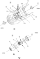
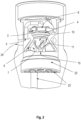
- Fig. 1 shows in Figure (a) a liquid jet device 20 according to the invention in a perspective view with a rectangular breakout of the housing 21 and in Figure (b) a liquid jet device 20 according to the invention in an exploded view.
- the housing 21 of the liquid jet device 20 is designed here to be essentially rotationally symmetrical. But it cannot be rotationally symmetrical either.
- the housing 21 has a recess on the inside, which is adapted to accommodate a swirling device 1 according to the invention by inserting the swirling device 1 into the recess of the housing 21 in the axial direction (along the longitudinal axis LA).
- the housing 21 On the open side (side on which the swirling device 1 is inserted into the housing 21), the housing 21 has an at least partially circumferential radial projection 21a, which serves as a stop for the swirling device 1.
- the swirling device 1 itself also has an at least partially circumferential radial projection 12 at its rear end, which corresponds to the radial projection 21a of the housing 21.
- the swirling device 1 is or can be pushed into the housing 21 until the radial projection 12 of the swirling device 1 rests on the radial projection 21a of the housing 21.
- the length of the swirling device 1 and the depth of the recess in the housing 21 are dimensioned such that when the swirling device 1 is completely accommodated in the housing 21 (when the radial projection 12 of the swirling device 1 rests on the radial projection 21a of the housing 21) between a cavity is formed at the front end of the swirling device 1 and the housing wall of the housing 21 opposite the front end of the swirling device 1.
- This cavity is referred to below as a calming chamber 22, the purpose of which is described in more detail below.
- the outer contour 13 of the swirling device 1 corresponds to the inner contour 21b of the housing 21.
- the calming chamber 22 is preferably separated from the rear part of the housing recess in a fluid and gas-tight manner.
- a circumferential sealing ring can be arranged at the front end of the swirling device 1.
- the housing 21 At the front end of the housing 21 it has a number of flow straighteners 23. As shown in figure (a), these can be provided in the front housing wall of the housing 21 as axially extending boreholes which open into the calming chamber 22.
- the number of flow straighteners 23 depends on the specific area of application of the liquid jet device 20 according to the invention. In one embodiment, only a single flow straightener 23 can be provided. If there are several flow straighteners 23, these can each have the same diameter - alternatively, it can also be provided that the flow straighteners 23 have different diameters. In figure (a), the flow straighteners 23 have a circular cross section. However, other cross-sections are possible.
- an internal thread can be provided in the housing 21 in order to equip the liquid jet device 20 according to the invention with an extension piece 30 if necessary.
- a circumferential sealing ring 31 can be arranged between the extension piece 30 and the swirling device 1, which can preferably comprise a sieve.
- the swirling device 1 can be made of a metal, in particular stainless steel, a plastic, or a biological material, in particular biofibers and/or lignin.
- the housing 21 can be made of a metal, in particular stainless steel, a plastic, or a biological material, in particular biofibers and/or lignin.
- the housing 21 and the swirling device 1 can be provided or manufactured as two separate parts, wherein the swirling device 1 can be inserted into the housing 21, as described above.
- the housing 21 and the swirling device 1 can also be provided or manufactured as an integral part.
- Steps b) and c) mentioned above are optional.
- step c) is carried out in a modified form.
- the fluid supplied to the swirl chamber is swirled.
- the swirled fluid then passes from the vortex chamber via an expansion chamber 10, in which a number of guide vanes 6 are arranged, into the settling chamber 22.
- excess gas can separate from the fluid.
- a fluid On the fluid inlet side, a fluid is first supplied to an antechamber 2, the fluid preferably being pressurized.
- the fluid then passes from the antechamber 2 into a swirl chamber 4 via a number of swirl channels 3.
- the swirl channels 3 are designed to run largely tangentially to the swirl chamber. This ensures that pressurized fluid exits almost tangentially to the vortex chamber 4 when it flows into the vortex chamber 4 and thus creates a fast vortex or vortex. Due to the largely tangential course of the swirl channels 3, a sufficiently strong vortex can be generated in the swirl chamber 4 even at a very low pressure with which the fluid is supplied to the swirl chamber 4.
- the orientation of the swirl channels can be selected so that a clockwise vortex is generated in the vortex chamber 4.
- the speed of the vortex in the vortex chamber 4 can be influenced by the pressure with which the fluid is supplied to the vortex chamber 4. The higher the The pressure is chosen, the greater the speed of the vortex. As the speed of the vortex increases, the centrifugal force acting on the vortex also increases, which creates a counterpressure, which in turn limits the mass of fluid supplied as the pressure increases. This ensures optimal function of the swirl chamber 4 over a very wide pressure range, namely the generation of a swirled gas-fluid mixture.
- the rapidly rotating vortex in the vortex chamber 4 creates a negative pressure area in the vortex chamber 4, namely inside the vortex.
- This negative pressure causes a gas (for example ambient air) to be sucked into the swirl chamber via a number of suction openings 5, which are formed in the wall of the swirling device 1.
- the suction openings 5 or the suction channels can open into a fluid inlet-side through hole 8 of the swirl chamber 4. It is advantageous if the through hole 8 runs coaxially to the longitudinal axis LA of the swirling device 1. This creates a centrally focused gas jet (e.g. an air jet) which shoots at high speed centrally into the swirl chamber 4 and into the expansion chamber 10 downstream of the swirl chamber. This ensures uniform mixing of the supplied fluid with the sucked gas. Since as the pressure with which the fluid is supplied to the liquid jet device 20 increases, the flow rate also increases and at the same time the pressure in the swirl chamber also decreases, more gas is sucked in and is mixed with the fluid. This also ensures that as the flow rate increases, the proportion of gas in the gas-fluid mixture generated remains largely constant.
- a centrally focused gas jet e.g. an air jet
- the suction openings 5 correspond to radial suction openings 24 in the housing 21.
- the ambient air therefore reaches the suction openings 5 of the swirling device 1 via the radial suction openings 24 and from there via suction channels to the through hole 8 of the swirl chamber 4.
- a radially circumferential support structure 9 can be provided at the through hole 8, which here is essentially annular and projects into the vortex chamber 4 in the axial direction.
- the support structure 9 ensures that the vortex generated does not collapse, which could impair or even prevent mixing of the gas with the fluid.
- An expansion chamber 10 is provided downstream of the vortex chamber 4, which essentially has a conical shape, in particular a frustoconical shape (internal volume), with the region 11 of the expansion chamber 10 with the smallest diameter facing the vortex chamber 4. This means that the diameter of the expansion chamber 10 increases downstream, which ensures that the gas-fluid mixture that passes from the swirl chamber 4 into the expansion chamber 10 expands.
- a plurality of guide vanes 6 are arranged in the expansion chamber 10, each of which can have a curved guide surface 7.
- the guide vanes 6 are arranged in the expansion chamber 10 in such a way that they receive the gas-fluid mixture from the vortex chamber 4 and lead it via the respective guide surfaces 7 into the settling chamber 22 downstream of the expansion chamber 10, whereby the flow direction and the angular momentum of the gas-fluid -Mixture can be influenced.
- the gas-fluid mixture supplied to the settling chamber 22 now has a significantly reduced vortex speed, which allows the fluid saturated with the gas to be separated from excess gas.
- a number of flow straighteners 23 are connected downstream of the calming chamber 22, through which the gas-fluid mixture is led out of the liquid jet device 20.
- the flow straighteners 23 can be designed as axially extending boreholes. From the liquid jet device 20 then rectified gas-fluid jets (e.g. water enriched with air) emerge.
- the emerging jet is compactly shaped and is suitable, for example, for filling glasses or bottles.
- the liquid jet device 20 can be used, for example, as a jet regulator for household water fittings.
Landscapes
- Jet Pumps And Other Pumps (AREA)
Priority Applications (1)
| Application Number | Priority Date | Filing Date | Title |
|---|---|---|---|
| EP22186438.2A EP4309799A1 (fr) | 2022-07-22 | 2022-07-22 | Dispositif de tourbillonement d'un liquide |
Applications Claiming Priority (1)
| Application Number | Priority Date | Filing Date | Title |
|---|---|---|---|
| EP22186438.2A EP4309799A1 (fr) | 2022-07-22 | 2022-07-22 | Dispositif de tourbillonement d'un liquide |
Publications (1)
| Publication Number | Publication Date |
|---|---|
| EP4309799A1 true EP4309799A1 (fr) | 2024-01-24 |
Family
ID=82701688
Family Applications (1)
| Application Number | Title | Priority Date | Filing Date |
|---|---|---|---|
| EP22186438.2A Withdrawn EP4309799A1 (fr) | 2022-07-22 | 2022-07-22 | Dispositif de tourbillonement d'un liquide |
Country Status (1)
| Country | Link |
|---|---|
| EP (1) | EP4309799A1 (fr) |
Citations (5)
| Publication number | Priority date | Publication date | Assignee | Title |
|---|---|---|---|---|
| US4616784A (en) * | 1984-11-20 | 1986-10-14 | Parker Hannifin Corporation | Slurry atomizer |
| US5143295A (en) * | 1989-11-21 | 1992-09-01 | Toto Ltd. | Bubbly water outlet device |
| US5934555A (en) * | 1996-03-05 | 1999-08-10 | Abb Research Ltd. | Pressure atomizer nozzle |
| DE10240667A1 (de) | 2002-09-04 | 2004-03-18 | Uwe Sonnenrein | Vorrichtung zur Anreicherung von Gas oder Gasmischungen in trinkbarem Wasser sowie Verfahren zur Anreicherung von Gas oder Gasmischungen in trinkbarem Wasser |
| RU2657493C1 (ru) * | 2017-09-07 | 2018-06-14 | Олег Савельевич Кочетов | Центробежная форсунка |
-
2022
- 2022-07-22 EP EP22186438.2A patent/EP4309799A1/fr not_active Withdrawn
Patent Citations (5)
| Publication number | Priority date | Publication date | Assignee | Title |
|---|---|---|---|---|
| US4616784A (en) * | 1984-11-20 | 1986-10-14 | Parker Hannifin Corporation | Slurry atomizer |
| US5143295A (en) * | 1989-11-21 | 1992-09-01 | Toto Ltd. | Bubbly water outlet device |
| US5934555A (en) * | 1996-03-05 | 1999-08-10 | Abb Research Ltd. | Pressure atomizer nozzle |
| DE10240667A1 (de) | 2002-09-04 | 2004-03-18 | Uwe Sonnenrein | Vorrichtung zur Anreicherung von Gas oder Gasmischungen in trinkbarem Wasser sowie Verfahren zur Anreicherung von Gas oder Gasmischungen in trinkbarem Wasser |
| RU2657493C1 (ru) * | 2017-09-07 | 2018-06-14 | Олег Савельевич Кочетов | Центробежная форсунка |
Similar Documents
| Publication | Publication Date | Title |
|---|---|---|
| EP0604741B1 (fr) | Buse à tourbillonnement pour pulvériser un liquide | |
| EP3204168B1 (fr) | Buse de pulvérisation | |
| EP2369231B1 (fr) | Dispositif de mélange pour un brûleur à gaz | |
| EP1243343A1 (fr) | Buse de vaporisation à deux fluides | |
| WO2007098865A1 (fr) | Tuyere a deux matieres dotee de tuyeres d'air secondaire disposees en cercle | |
| DE10019759C2 (de) | Statisches Mischsystem | |
| DE102011078857A1 (de) | Sprühdüse und Verfahren zum Erzeugen wenigstens eines rotierenden Sprühstrahls | |
| EP1961487B1 (fr) | Dispositif de graissage à froid en quantités minimales | |
| EP2872258B1 (fr) | Pistolet de projection à gaz froid avec injecteur de poudre | |
| EP0801990B1 (fr) | Buse de pulvérisation, en particulier pour la pulvérisation d'eau dans les installations de protection contre l'incendie | |
| DE19841401C2 (de) | Zweistoff-Flachstrahldüse | |
| DE69408326T2 (de) | Plasmabrenner | |
| DE10392296T5 (de) | Strömungsgleichrichter für einen Fluidstrom und Zapfpistole | |
| DE19708218C2 (de) | Gasbrenner | |
| EP4309799A1 (fr) | Dispositif de tourbillonement d'un liquide | |
| DE3640818C1 (en) | Spray head for producing an air-liquid mixture, in particular for a cooling device | |
| DE202022104142U1 (de) | Vorrichtung zur Verwirbelung einer Flüssigkeit | |
| EP3638424B1 (fr) | Buse de pulverisation | |
| EP0674941B1 (fr) | Dispositif pour la fabrication d'une émulsion huile-eau | |
| EP2764909A2 (fr) | Dispositif de mélange pour cartouches bicomposants | |
| DE4110596C2 (fr) | ||
| DE1557222C3 (de) | Vorrichtung zum mischen gasfoermiger stoffe | |
| DE10041164B4 (de) | Niederdruck-Zerstäubungsvorrichtung | |
| DE102013002235A1 (de) | Luftansaugvorrichtung für eine Sanitärbrause | |
| EP0264689A1 (fr) | Appareil producteur de mousse |
Legal Events
| Date | Code | Title | Description |
|---|---|---|---|
| PUAI | Public reference made under article 153(3) epc to a published international application that has entered the european phase |
Free format text: ORIGINAL CODE: 0009012 |
|
| STAA | Information on the status of an ep patent application or granted ep patent |
Free format text: STATUS: THE APPLICATION HAS BEEN PUBLISHED |
|
| AK | Designated contracting states |
Kind code of ref document: A1 Designated state(s): AL AT BE BG CH CY CZ DE DK EE ES FI FR GB GR HR HU IE IS IT LI LT LU LV MC MK MT NL NO PL PT RO RS SE SI SK SM TR |
|
| STAA | Information on the status of an ep patent application or granted ep patent |
Free format text: STATUS: THE APPLICATION IS DEEMED TO BE WITHDRAWN |
|
| 18D | Application deemed to be withdrawn |
Effective date: 20240725 |