EP4310016A2 - Caisse à fruits repliable - Google Patents
Caisse à fruits repliable Download PDFInfo
- Publication number
- EP4310016A2 EP4310016A2 EP23186633.6A EP23186633A EP4310016A2 EP 4310016 A2 EP4310016 A2 EP 4310016A2 EP 23186633 A EP23186633 A EP 23186633A EP 4310016 A2 EP4310016 A2 EP 4310016A2
- Authority
- EP
- European Patent Office
- Prior art keywords
- side wall
- crate
- hinge
- base
- crate according
- Prior art date
- Legal status (The legal status is an assumption and is not a legal conclusion. Google has not performed a legal analysis and makes no representation as to the accuracy of the status listed.)
- Pending
Links
Images





Classifications
-
- B—PERFORMING OPERATIONS; TRANSPORTING
- B65—CONVEYING; PACKING; STORING; HANDLING THIN OR FILAMENTARY MATERIAL
- B65D—CONTAINERS FOR STORAGE OR TRANSPORT OF ARTICLES OR MATERIALS, e.g. BAGS, BARRELS, BOTTLES, BOXES, CANS, CARTONS, CRATES, DRUMS, JARS, TANKS, HOPPERS, FORWARDING CONTAINERS; ACCESSORIES, CLOSURES, OR FITTINGS THEREFOR; PACKAGING ELEMENTS; PACKAGES
- B65D11/00—Containers having bodies formed by interconnecting or uniting two or more rigid, or substantially rigid, components made wholly or mainly of plastics material
- B65D11/18—Containers having bodies formed by interconnecting or uniting two or more rigid, or substantially rigid, components made wholly or mainly of plastics material collapsible, i.e. with walls hinged together or detachably connected
- B65D11/1833—Containers having bodies formed by interconnecting or uniting two or more rigid, or substantially rigid, components made wholly or mainly of plastics material collapsible, i.e. with walls hinged together or detachably connected whereby all side walls are hingedly connected to the base panel
-
- B—PERFORMING OPERATIONS; TRANSPORTING
- B65—CONVEYING; PACKING; STORING; HANDLING THIN OR FILAMENTARY MATERIAL
- B65D—CONTAINERS FOR STORAGE OR TRANSPORT OF ARTICLES OR MATERIALS, e.g. BAGS, BARRELS, BOTTLES, BOXES, CANS, CARTONS, CRATES, DRUMS, JARS, TANKS, HOPPERS, FORWARDING CONTAINERS; ACCESSORIES, CLOSURES, OR FITTINGS THEREFOR; PACKAGING ELEMENTS; PACKAGES
- B65D11/00—Containers having bodies formed by interconnecting or uniting two or more rigid, or substantially rigid, components made wholly or mainly of plastics material
- B65D11/20—Details of walls made of plastics material
- B65D11/22—Reinforcing for strengthening parts of members
-
- B—PERFORMING OPERATIONS; TRANSPORTING
- B65—CONVEYING; PACKING; STORING; HANDLING THIN OR FILAMENTARY MATERIAL
- B65D—CONTAINERS FOR STORAGE OR TRANSPORT OF ARTICLES OR MATERIALS, e.g. BAGS, BARRELS, BOTTLES, BOXES, CANS, CARTONS, CRATES, DRUMS, JARS, TANKS, HOPPERS, FORWARDING CONTAINERS; ACCESSORIES, CLOSURES, OR FITTINGS THEREFOR; PACKAGING ELEMENTS; PACKAGES
- B65D21/00—Nestable, stackable or joinable containers; Containers of variable capacity
- B65D21/02—Containers specially shaped, or provided with fittings or attachments, to facilitate nesting, stacking, or joining together
- B65D21/0209—Containers specially shaped, or provided with fittings or attachments, to facilitate nesting, stacking, or joining together stackable or joined together one-upon-the-other in the upright or upside-down position
-
- B—PERFORMING OPERATIONS; TRANSPORTING
- B65—CONVEYING; PACKING; STORING; HANDLING THIN OR FILAMENTARY MATERIAL
- B65D—CONTAINERS FOR STORAGE OR TRANSPORT OF ARTICLES OR MATERIALS, e.g. BAGS, BARRELS, BOTTLES, BOXES, CANS, CARTONS, CRATES, DRUMS, JARS, TANKS, HOPPERS, FORWARDING CONTAINERS; ACCESSORIES, CLOSURES, OR FITTINGS THEREFOR; PACKAGING ELEMENTS; PACKAGES
- B65D25/00—Details of other kinds or types of rigid or semi-rigid containers
- B65D25/005—Side walls formed with an aperture or a movable portion arranged to allow removal or insertion of contents
-
- B—PERFORMING OPERATIONS; TRANSPORTING
- B65—CONVEYING; PACKING; STORING; HANDLING THIN OR FILAMENTARY MATERIAL
- B65D—CONTAINERS FOR STORAGE OR TRANSPORT OF ARTICLES OR MATERIALS, e.g. BAGS, BARRELS, BOTTLES, BOXES, CANS, CARTONS, CRATES, DRUMS, JARS, TANKS, HOPPERS, FORWARDING CONTAINERS; ACCESSORIES, CLOSURES, OR FITTINGS THEREFOR; PACKAGING ELEMENTS; PACKAGES
- B65D25/00—Details of other kinds or types of rigid or semi-rigid containers
- B65D25/20—External fittings
- B65D25/205—Means for the attachment of labels, cards, coupons or the like
-
- B—PERFORMING OPERATIONS; TRANSPORTING
- B65—CONVEYING; PACKING; STORING; HANDLING THIN OR FILAMENTARY MATERIAL
- B65D—CONTAINERS FOR STORAGE OR TRANSPORT OF ARTICLES OR MATERIALS, e.g. BAGS, BARRELS, BOTTLES, BOXES, CANS, CARTONS, CRATES, DRUMS, JARS, TANKS, HOPPERS, FORWARDING CONTAINERS; ACCESSORIES, CLOSURES, OR FITTINGS THEREFOR; PACKAGING ELEMENTS; PACKAGES
- B65D85/00—Containers, packaging elements or packages, specially adapted for particular articles or materials
- B65D85/30—Containers, packaging elements or packages, specially adapted for particular articles or materials for articles particularly sensitive to damage by shock or pressure
- B65D85/34—Containers, packaging elements or packages, specially adapted for particular articles or materials for articles particularly sensitive to damage by shock or pressure for fruit, e.g. apples, oranges or tomatoes
-
- B—PERFORMING OPERATIONS; TRANSPORTING
- B65—CONVEYING; PACKING; STORING; HANDLING THIN OR FILAMENTARY MATERIAL
- B65D—CONTAINERS FOR STORAGE OR TRANSPORT OF ARTICLES OR MATERIALS, e.g. BAGS, BARRELS, BOTTLES, BOXES, CANS, CARTONS, CRATES, DRUMS, JARS, TANKS, HOPPERS, FORWARDING CONTAINERS; ACCESSORIES, CLOSURES, OR FITTINGS THEREFOR; PACKAGING ELEMENTS; PACKAGES
- B65D2203/00—Decoration means, markings, information elements, contents indicators
- B65D2203/02—Labels
Definitions
- the invention relates to crates for shipping products, particularly agricultural products, and more particularly to collapsible crates for such products.
- Crates for shipping of products, particularly fruit and similar agricultural products may be constructed from polymers such as but not limited to polyolefins. Their advantages over crates made of paper or cardboard (e.g. cartons) include greater sturdiness, aeration of the content and resistance to humidity. In some configurations, polymer crates may also be re-usable and therefore generally foldable for return shipping. Polymer crates may be in a fixed form, in which panels of the crate are fixedly joined, or a collapsible form, in which, side panels are hingedly connected with a base between a folded and erected configuration.
- crates for shipping products such as but not limited to agricultural products.
- the crates described herein may be configurable between an erected configuration and a folded configuration, and the crates may be stackable in both the folded configuration and the erected configuration.
- side walls of the crate may be hingedly connected to a base of the crate via floating hinge mechanisms.
- the floating hinge mechanisms may allow for opposing side walls to be folded on top of each other in the folded configuration while allowing for either side wall to be an uppermost or lowermost wall when folded (e.g., the side walls do not need to fold in a specific order).
- the floating hinge mechanisms may also facilitate movement of the side walls between the erected configuration and the folded configuration and vice versa.
- the crates described herein include friction features on one or more side walls of the crate, including but not limited to a first side wall of the crate (e.g., when the crate is a rectangular shape / does not have uniform side wall lengths). When included, such friction features may minimize or prevent labels from sticking permanently to the crate. Additionally or alternatively, during a lifting operation, the friction features of one crate may frictionally engage friction features of an adjacent crate to prevent or minimize slippage between the crates and/or to improve stability of the crates.
- Such frictional engagement may improve the stability of layers of a pallet or stack of crates, facilitating movement of multiple crates, such as when a set of crates is engaged by a layer picker or other suitable piece of machinery for engaging a set of crates from multiple sides to push the crates together for lifting or other handling.
- the crates described herein include at least one side wall with a flex portion having a thickness different from a thickness of another portion of the side wall.
- the flex portion and/or thickness variation may allow the crate to flex and conform to the products within the crate.
- the flex portion and/or thickness variation may allow the crate to conform to agricultural products such as fruit within the crate.
- the crates described herein include a side wall with one or more sampling windows that may be used, for example, during a quality check of the content of the crate.
- the sampling windows may be provided at different locations on the side wall and/or relative to each other to facilitate access to different portions of the crate interior.
- the sampling windows may have different shapes and/or dimensions, which optionally may facilitate different quality checks.
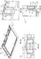
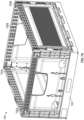
- FIG. 1 illustrates an example of a crate 100 according to embodiments.
- the crate 100 generally includes a base 102, first side walls 104A-B, and second side walls 106A-B. While the crate 100 may have various dimensions as desired, in some embodiments, the first side walls 104A-B are "long" side walls 104A-B and the second side walls 106A-B are "short" side walls 106A-B having a length less than the first side walls 104A-B.
- the crate 100 may be constructed from various materials as desired, including but not limited to polymers.
- FIGS. 2A-D illustrate the base 102 in detail.
- the base 102 includes a perimeter wall 108.
- Various venting apertures are optionally defined in the base 102.
- the perimeter wall 108 may include one or more first hinge receivers 114 for engaging corresponding hinges 130 of the first side walls 104A-B and one or more second hinge receivers 116 for engaging corresponding hinges 172 of the second side walls 106A-B.
- the hinge receivers 114, 116 may allow for the side walls 104, 106 to be hingedly connected to the base 102 while allowing for movement between an erected configuration and a folded configuration relative to the base 102.
- the first hinge receivers 114 may be floating hinge receivers defining a receiving area 118 with an opening 120.
- the opening 120 provides access to the receiving area 118 and is at a top end 122 of the perimeter wall 108.
- the opening 120 has a width, and the width may be a minimum width of the receiving area 118. The width may be in a direction transverse to a pivot axis of the hinge, for example.
- a portion of the receiving area 118 opposite from the opening 120 may define a maximum width of the receiving area.
- the receiving area 118 includes a receiving area surface 126 (see FIG. 2D ).
- the receiving area surface 126 includes an inner surface portion 127A and an outer surface portion 127B.
- a ledge 128 is provided on the receiving area surface 126.
- the ledge 128 may be provided on the receiving area surface 126 at a location that is spaced apart and/or opposite from the opening 120.
- a protrusion 138 of the hinge 130 of a first side wall 104 may engage the ledge 128 when the first side wall 104 is in the erected configuration.
- each first hinge receiver 114 may include one or more slots 131 for receiving corresponding arms 134 of the hinge 130 of the first side walls 104.
- FIGS. 3A-F illustrate a first side wall 104 in detail.
- the first side wall 104 generally includes a first side 140 and a second side 142, and when the first side wall 104 is in the erected configuration, the first side 140 may face inwards and the second side 142 may face outwards.
- the first side wall 104 also includes a first end 144 and a second end 146, and a distance from the first end 144 to the second end 146 is a length of the first side wall 104.
- the first side wall 104 includes end portions 148, 150 having a first thickness and a center portion 152 between the end portions 148, 150 having a second thickness that is different from the first thickness.
- the second thickness is less than the first thickness such that the center portion 152 is a flex portion allowing the crate to conform to contents of the crate 100.
- the center portion 152 may extend continuously between the end portions 148, 150.
- the center portion 152 optionally is at least 50% the length of the first side wall 104.
- the center portion 152 may be offset towards the first side 140 or the second side 142 such that the center portion 152 is recessed on the second side 142 or the first side 140.
- One or more venting apertures may be defined in the center portion 152, although they need not be included in other embodiments.
- the first side wall 104 may include one or more first hinges 130 that are selectively engageable with corresponding first hinge receivers 114 of the base 102.
- each first hinge 130 may include a rod 132 supported by one or more arms 134 such that the rod 132 is spaced apart from a lower edge 136 of the first side wall 104.
- a protrusion 138 extends outwards from the rod 132 in a direction that the first side 140 is facing. The protrusion 138 may selectively engage the ledge 128 of the first hinge receiver 114 when the first side wall 104 is in the erected configuration.
- the first side wall 104 may include a stopper 154.
- the stopper 154 may be engaged by a latch 174 of the second side wall 106 as discussed in detail below.
- the stopper 154 may extend from one or both end portions 148, 150 and in a direction of the first side 140 of the first side wall 104.
- FIGS. 4A-D illustrate a second side wall 106 in detail.
- the second side wall 106 generally includes a first side 156, a second side 158, a first end 160, and a second end 162.
- first side 156 may face inwards and the second side 158 may face outwards.
- the second side wall 106 optionally includes end portions 164, 166 and a center portion 168 where a thickness of the center portion 168 is different from (e.g., less than) a thickness of the end portions 164, 166.
- the center portion 168 is a flex portion allowing the crate to conform to contents of the crate 100. As best illustrated in FIG. 4A , the center portion 168 may extend continuously between the end portions 164, 166. Similar to the center portion 152, the center portion 168 optionally may be offset towards the first side 156 or the second side 158 such that the center portion 168 is recessed on the second side 158 or the first side 156.
- a sampling window 170 is defined in the second side wall 106.
- the sampling window 170 is defined at least partially by the center portion 168.
- the sampling window 170 may facilitate access to an interior region of the crate 100 when the crate 100 is in the erected configuration.
- the sampling window 170 optionally may be a handling or gripping location for a user to grab or grasp when handling the crate 100.
- the second side wall 106 includes one or more second hinges 172 that are selectively engageable with corresponding second hinge receivers 116 of the base 102.
- the second hinges 172 may be similar to or different from the first hinges 130 as desired.
- the second side wall 106 includes one or more latches 174.
- the latches 174 are integral or monolithic with the second side wall 106, and the latches 174 may be movable or flexible relative to the second side wall 106 such that the latches 174 may flex inwards or outwards relative to the second side wall 106 as desired.
- the latches 174 include an engagement surface 176 that may selectively engage corresponding stoppers 154 on the first side walls 104 to facilitate retention of the crate 100 in the erected configuration.
- the engagement surface 176 extends at an oblique angle relative to the first side 156, which may facilitate engagement with or disengagement from the corresponding latch 174.
- the latches 174 are configured to retain the stoppers 154 between the engagement surfaces 176 and a retaining ledge 177 in the erected configuration.
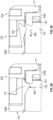
- FIGS. 5A-E illustrate a floating hinge mechanism 501 that includes the first hinges 130 and the first hinge receivers 114.
- the floating hinge mechanism 501 may allow for movement of the first side walls 104A-B between an erected configuration ( FIG. 5A ) and a collapsed configuration ( FIG. 5C ).
- the rods 132 of the first hinges 130 are positioned within the receiving areas 118 of the first hinge receivers 114.
- the rods 132 may be at a location within the receiving areas 118 spaced apart from the opening 120 (or in a lower portion 178 of the receiving area 118 relative to the top end 122, such as adjacent to and/or in contact with a bottom end of the first hinge receiver 114).
- the rods 132 may contact outer surface portions 127B of the receiving area surface 126, which may provide stability to the first side walls 104 in the erected configuration.
- the protrusion 138 may engage the ledge 128 when the first side wall 104 is in the erected configuration, which may provide stability to the first side walls 104 in the erected configuration.
- first side walls 104A-B may be folded on top of each other. While the first side wall 104A is illustrated on top of the first side wall 104B, the floating hinge mechanism 501 allows for either first side wall 104A-B to be a top or bottom of the folded side walls (e.g., the side walls need not be erected or collapsed in a specific order relative to one another). As an example, and referring to FIGS.
- the receiving area 118 may allow for the rods 132 to be at various vertical positions (e.g., to float) within the receiving area 126 such that the rods 132 of the top first side wall 104A are proximate to the top end 122 ( FIG. 5D ) when the side wall 104A is in the collapsed configuration while the rods 132 of the bottom first side wall 104B are proximate to the lower portion 178 ( FIG. 5E ) when the side wall 104B is in the collapsed configuration.
- the rods 132 may be positioned within the receiving area 118 via the opening 120 when the first side walls 104 are in the collapsed configuration.
- FIGS. 6A-E illustrate a latch mechanism 603 that includes the latches 174 and the stoppers 154.
- the engagement surface 176 of each latch 174 may engage the corresponding stopper 154 and/or retain at least a portion of the stopper 154 between the engagement surface 176 and the retaining ledge 177. Retention of the stopper 154 between the engagement surface 176 and the retaining ledge 177 may improve stability of the first side walls 104 and maintain the first side walls 104 in the erected configuration.
- the arrangement of the stopper 154 may obstruct inadvertent flexing inward of the latch 174 and thus block inadvertent actuation of the latch 174 in use.
- a force (represented by arrow 605 in FIG. 6D ) may be applied to the latch 174 such that the latch 174 is flexed outwards (represented by blue outline 607 in FIG. 6E ).
- the latch 174 flexed outwards in turn allows for the first side wall 104 to collapse inwards (represented by arrow 609) by no longer obstructing or retaining the stopper 154 with the retaining ledge 177.
- the angled engagement surface 176 may facilitate flexing of the latch 174 outwards.
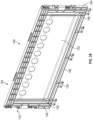
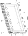
- FIGS. 7A-B , 8A-C , and 9A-C illustrate a crate 700 that is substantially similar to the crate 100 and includes the base 102, first side walls 704A-B, and second side walls 706A-B.
- the first side walls 704 and the second side walls 706 are movable between an erected configuration ( FIG. 7A ) and a collapsed configuration ( FIG. 7B ).
- Features shown and described with respect to the crate 700 may be included in the crate 100 or vice versa.
- first side walls 704 of the crate 700 are substantially similar to the first side walls 104 except that the first side walls 704 additionally include friction features 780.
- the friction features 780 may minimize or prevent labels from permanently adhering to the crate 700 and/or may facilitate the removal of such stickers or labels from the crate 700.
- the friction features 780 are provided to minimize or prevent slippage during a lifting movement of the crate 700.
- the friction features 780 may engage friction features 780 on an adjacent crate 700 in a stack of crates 700, and/or the friction features 780 may be engaged by a user and/or a lifting machine (which may include a machine typically called a "layer picker" and that may include suitable panels and actuators to press against multiple sides of a set of crates to push the crates together for lifting or other handling).
- the friction features 780 in addition to the center portion 152 act as a flex portion that allows for content of the crate (e.g., fruit) to push and flex the first side walls 104 outwards and into engagement with friction features 780 of an adjacent crate 700.
- the friction features 780 are a plurality of ribs 783 extending between the end portions 148, 150 although other friction features 780 may be used as desired.
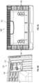
- the second side wall 706 is substantially similar to the second side wall 106. Compared to the second side wall 106, the second side wall 706 includes one or more additional sampling windows 782. As best illustrated in FIG. 9A , the sampling windows 782 optionally may have a different shape and/or profile compared to the sampling window 170. In such embodiments, the different sampling windows 782 may facilitate different types of access to the interior of the crate 700 compared to the sampling window 170. The sampling windows 782 are provided at locations that are vertically and/or horizontally offset from the sampling window 782 such that different locations of the interior of the crate 700 may be accessed.
- the sampling windows 782 are provided in lower corners of the crate side walls to facilitate removal of fruit, such as a single banana, when the fruit is packed within the crate 700.
- the sampling windows 782 are shaped and sized to accommodate a knife or other cutting tool if needed to cut a single banana from the bunch for sampling.
- the second side wall 706 additionally includes a flex limiter 784 on the latch 174.
- the flex limiter 784 may limit an outward flexing or movement of the latch 174.
- the flex limiter 784 optionally may provide tactile feedback to a user indicating when the latch 174 has moved a sufficient distance allowing the crate 700 to be collapsed.
- Label fingers 786 may be included on the second side wall 706.
- the label fingers 786 may correspond to tabs or other protrusions suitably arranged to receive and/or hold a card or other label on the crate, such as to indicate content identification, weight, origin, destination, and/or other information.
- Some label fingers 786 may extend vertically (such as shown along a lower portion of the second side wall 706), and some label fingers 786 may extend horizontally (such as shown along lateral portions of the second side wall 706), although other orientations may be utilized (including but not limited to partially horizontal and partially vertical).
- the second side wall 706 include at least one mounting surface that may be substantially free of ribs 783 and/or other friction features 780, e.g., so as to be smooth to facilitate installation of a label via the label fingers 786 or otherwise.
- the sampling windows 782 and/or 170 may be of a larger, smaller, or different size than shown in FIG. 9A .
- the second side wall 906 (which may be substantially similar to the second side wall 706) includes a set of windows 982 arranged vertically one above another and/or an upper central sampling window 970 that is suitably sized to form a handle for lifting the crate.
- crates are for illustrative purposes only and should not be considered limiting, and in other embodiments, other types of features may be provided with crates as desired.
- device “12A” refers to an instance of a device class, which may be referred to collectively as devices “12” and any one of which may be referred to generically as a device “12".
- device “12A” refers to an instance of a device class, which may be referred to collectively as devices “12” and any one of which may be referred to generically as a device “12”.
- like numerals are intended to represent like elements.
- the meaning of "a,” “an,” and “the” includes singular and plural references unless the context clearly dictates otherwise.
Landscapes
- Engineering & Computer Science (AREA)
- Mechanical Engineering (AREA)
- Rigid Containers With Two Or More Constituent Elements (AREA)
Applications Claiming Priority (1)
| Application Number | Priority Date | Filing Date | Title |
|---|---|---|---|
| US202263390843P | 2022-07-20 | 2022-07-20 |
Publications (2)
| Publication Number | Publication Date |
|---|---|
| EP4310016A2 true EP4310016A2 (fr) | 2024-01-24 |
| EP4310016A3 EP4310016A3 (fr) | 2024-03-20 |
Family
ID=87426855
Family Applications (1)
| Application Number | Title | Priority Date | Filing Date |
|---|---|---|---|
| EP23186633.6A Pending EP4310016A3 (fr) | 2022-07-20 | 2023-07-20 | Caisse à fruits repliable |
Country Status (2)
| Country | Link |
|---|---|
| US (1) | US20240025594A1 (fr) |
| EP (1) | EP4310016A3 (fr) |
Family Cites Families (3)
| Publication number | Priority date | Publication date | Assignee | Title |
|---|---|---|---|---|
| JP4852487B2 (ja) * | 2007-07-11 | 2012-01-11 | 三甲株式会社 | 折り畳みコンテナー |
| DE102009049184A1 (de) * | 2009-04-15 | 2010-11-04 | Ifco Systems Gmbh | Kiste mit faltbaren Seitenwänden und Verriegelungsmechanismen mit Überlastschutz |
| DE102016114065B3 (de) * | 2016-07-29 | 2017-09-14 | Schoeller Allibert Gmbh | Scharnieranordnung und Behälter mit einer solchen Scharnieranordnung |
-
2023
- 2023-07-20 EP EP23186633.6A patent/EP4310016A3/fr active Pending
- 2023-07-20 US US18/224,221 patent/US20240025594A1/en active Pending
Also Published As
| Publication number | Publication date |
|---|---|
| US20240025594A1 (en) | 2024-01-25 |
| EP4310016A3 (fr) | 2024-03-20 |
Similar Documents
| Publication | Publication Date | Title |
|---|---|---|
| EP1785360B1 (fr) | Conteneur pliable | |
| JP5401601B2 (ja) | 折り畳み式側壁および、過荷重防止ロック機構を備える箱 | |
| JP5442847B2 (ja) | 安定した側面構造を持つ折り畳み式側壁を有する箱 | |
| CA2688726C (fr) | Carton avec plus grande ouverture d'acces | |
| US11738907B2 (en) | Stackable and ventable containers | |
| US20150375558A1 (en) | Collapsible file box with integrated file hanging rails | |
| US20200198880A1 (en) | Reusable plastic container for shipping of produce | |
| JP2012523998A (ja) | 折り畳み式および自動ロック式側壁を有する箱 | |
| DK2726379T3 (en) | PLASTIC CONTAINER WITH FOLDABLE sidewall, AND USE OF A CONTAINER. | |
| EP3113599B1 (fr) | Agencement de conteneurs de fret en plastique | |
| US11434048B2 (en) | Nestable containers | |
| WO2014176292A1 (fr) | Conteneur en plastique réutilisable destiné au stockage et à l'expédition de marchandises | |
| EP4310016A2 (fr) | Caisse à fruits repliable | |
| US11518605B1 (en) | Packaging unit | |
| US20110272455A1 (en) | Reusable envelope tray system | |
| EP2161209A1 (fr) | Conditionnement à structure en nid d'abeille | |
| KR20220156086A (ko) | 용기 블랭크 | |
| US20060138206A1 (en) | Stackable container and container blank (L corner) | |
| US20090159488A1 (en) | Container having top and bottom reinforcement | |
| US20060138205A1 (en) | Stackable container with air cell corner assembly and associated container blank | |
| US20260125180A1 (en) | Collapsible agricultural crate | |
| US20060138204A1 (en) | Stackable container with angled corner panel and container blank | |
| JP4692538B2 (ja) | 梱包装置 | |
| CN223253684U (zh) | 一种禽蛋包装盒 | |
| EP4063286A1 (fr) | Caisse pliable avec ensemble de barre oscillante |
Legal Events
| Date | Code | Title | Description |
|---|---|---|---|
| PUAI | Public reference made under article 153(3) epc to a published international application that has entered the european phase |
Free format text: ORIGINAL CODE: 0009012 |
|
| STAA | Information on the status of an ep patent application or granted ep patent |
Free format text: STATUS: THE APPLICATION HAS BEEN PUBLISHED |
|
| AK | Designated contracting states |
Kind code of ref document: A2 Designated state(s): AL AT BE BG CH CY CZ DE DK EE ES FI FR GB GR HR HU IE IS IT LI LT LU LV MC ME MK MT NL NO PL PT RO RS SE SI SK SM TR |
|
| PUAL | Search report despatched |
Free format text: ORIGINAL CODE: 0009013 |
|
| AK | Designated contracting states |
Kind code of ref document: A3 Designated state(s): AL AT BE BG CH CY CZ DE DK EE ES FI FR GB GR HR HU IE IS IT LI LT LU LV MC ME MK MT NL NO PL PT RO RS SE SI SK SM TR |
|
| RIC1 | Information provided on ipc code assigned before grant |
Ipc: B65D 6/18 20060101AFI20240214BHEP |
|
| STAA | Information on the status of an ep patent application or granted ep patent |
Free format text: STATUS: REQUEST FOR EXAMINATION WAS MADE |
|
| 17P | Request for examination filed |
Effective date: 20240919 |
|
| RBV | Designated contracting states (corrected) |
Designated state(s): AL AT BE BG CH CY CZ DE DK EE ES FI FR GB GR HR HU IE IS IT LI LT LU LV MC ME MK MT NL NO PL PT RO RS SE SI SK SM TR |