EP4310030A1 - Dispositif d'entraînement planaire et procédé de fonctionnement d'un dispositif d'entraînement planaire - Google Patents
Dispositif d'entraînement planaire et procédé de fonctionnement d'un dispositif d'entraînement planaire Download PDFInfo
- Publication number
- EP4310030A1 EP4310030A1 EP23183720.4A EP23183720A EP4310030A1 EP 4310030 A1 EP4310030 A1 EP 4310030A1 EP 23183720 A EP23183720 A EP 23183720A EP 4310030 A1 EP4310030 A1 EP 4310030A1
- Authority
- EP
- European Patent Office
- Prior art keywords
- cleaning
- mover
- drive
- planar
- drive surface
- Prior art date
- Legal status (The legal status is an assumption and is not a legal conclusion. Google has not performed a legal analysis and makes no representation as to the accuracy of the status listed.)
- Pending
Links
Images

Classifications
-
- B—PERFORMING OPERATIONS; TRANSPORTING
- B08—CLEANING
- B08B—CLEANING IN GENERAL; PREVENTION OF FOULING IN GENERAL
- B08B1/00—Cleaning by methods involving the use of tools
- B08B1/20—Cleaning of moving articles, e.g. of moving webs or of objects on a conveyor
-
- A—HUMAN NECESSITIES
- A61—MEDICAL OR VETERINARY SCIENCE; HYGIENE
- A61L—METHODS OR APPARATUS FOR STERILISING MATERIALS OR OBJECTS IN GENERAL; DISINFECTION, STERILISATION OR DEODORISATION OF AIR; CHEMICAL ASPECTS OF BANDAGES, DRESSINGS, ABSORBENT PADS OR SURGICAL ARTICLES; MATERIALS FOR BANDAGES, DRESSINGS, ABSORBENT PADS OR SURGICAL ARTICLES
- A61L2/00—Disinfection or sterilisation of materials or objects, in general; Accessories therefor
- A61L2/26—Accessories
-
- B—PERFORMING OPERATIONS; TRANSPORTING
- B08—CLEANING
- B08B—CLEANING IN GENERAL; PREVENTION OF FOULING IN GENERAL
- B08B1/00—Cleaning by methods involving the use of tools
- B08B1/10—Cleaning by methods involving the use of tools characterised by the type of cleaning tool
- B08B1/12—Brushes
-
- B—PERFORMING OPERATIONS; TRANSPORTING
- B08—CLEANING
- B08B—CLEANING IN GENERAL; PREVENTION OF FOULING IN GENERAL
- B08B3/00—Cleaning by methods involving the use or presence of liquid or steam
- B08B3/02—Cleaning by the force of jets or sprays
-
- B—PERFORMING OPERATIONS; TRANSPORTING
- B08—CLEANING
- B08B—CLEANING IN GENERAL; PREVENTION OF FOULING IN GENERAL
- B08B3/00—Cleaning by methods involving the use or presence of liquid or steam
- B08B3/02—Cleaning by the force of jets or sprays
- B08B3/022—Cleaning travelling work
-
- B—PERFORMING OPERATIONS; TRANSPORTING
- B65—CONVEYING; PACKING; STORING; HANDLING THIN OR FILAMENTARY MATERIAL
- B65G—TRANSPORT OR STORAGE DEVICES, e.g. CONVEYORS FOR LOADING OR TIPPING, SHOP CONVEYOR SYSTEMS OR PNEUMATIC TUBE CONVEYORS
- B65G43/00—Control devices, e.g. for safety, warning or fault-correcting
-
- B—PERFORMING OPERATIONS; TRANSPORTING
- B65—CONVEYING; PACKING; STORING; HANDLING THIN OR FILAMENTARY MATERIAL
- B65G—TRANSPORT OR STORAGE DEVICES, e.g. CONVEYORS FOR LOADING OR TIPPING, SHOP CONVEYOR SYSTEMS OR PNEUMATIC TUBE CONVEYORS
- B65G45/00—Lubricating, cleaning, or clearing devices
- B65G45/10—Cleaning devices
-
- B—PERFORMING OPERATIONS; TRANSPORTING
- B65—CONVEYING; PACKING; STORING; HANDLING THIN OR FILAMENTARY MATERIAL
- B65G—TRANSPORT OR STORAGE DEVICES, e.g. CONVEYORS FOR LOADING OR TIPPING, SHOP CONVEYOR SYSTEMS OR PNEUMATIC TUBE CONVEYORS
- B65G54/00—Non-mechanical conveyors not otherwise provided for
-
- B—PERFORMING OPERATIONS; TRANSPORTING
- B65—CONVEYING; PACKING; STORING; HANDLING THIN OR FILAMENTARY MATERIAL
- B65G—TRANSPORT OR STORAGE DEVICES, e.g. CONVEYORS FOR LOADING OR TIPPING, SHOP CONVEYOR SYSTEMS OR PNEUMATIC TUBE CONVEYORS
- B65G54/00—Non-mechanical conveyors not otherwise provided for
- B65G54/02—Non-mechanical conveyors not otherwise provided for electrostatic, electric, or magnetic
-
- H—ELECTRICITY
- H02—GENERATION; CONVERSION OR DISTRIBUTION OF ELECTRIC POWER
- H02K—DYNAMO-ELECTRIC MACHINES
- H02K41/00—Propulsion systems in which a rigid body is moved along a path due to dynamo-electric interaction between the body and a magnetic field travelling along the path
- H02K41/02—Linear motors; Sectional motors
-
- H—ELECTRICITY
- H02—GENERATION; CONVERSION OR DISTRIBUTION OF ELECTRIC POWER
- H02K—DYNAMO-ELECTRIC MACHINES
- H02K2201/00—Specific aspects not provided for in the other groups of this subclass relating to the magnetic circuits
- H02K2201/18—Machines moving with multiple degrees of freedom
Definitions
- the invention relates to a planar drive device with the features of the preamble of patent claim 1.
- Planar drive devices with a drive table and electromagnetically coupled movers are known. Such devices can be used, for example, for transporting different transport goods and/or for arranging and operating work tools.
- contamination of the outer shell of the movers can regularly occur.
- substances from the immediate surroundings of the device can be picked up and/or spilled media from transported goods stick to the outer shell of the mover.
- the invention is based on the object of providing a device and a method which enable easy cleaning of the outer shell of the movers, in particular during ongoing operation of the device.
- the cleaning device By arranging the cleaning device on the drive table, it is possible to use an inherent function of the device - namely the mobility of the mover - in order to move the mover into the cleaning area and thus into direct spatial proximity to the cleaning device.
- the mover can be brought into the cleaning area and cleaned there, thereby minimizing the time required for cleaning
- manual intervention can be dispensed with.
- the device is particularly suitable for use as part of a pharmaceutical system. There, particularly high demands are placed on the cleanliness and sterility of the individual components and in particular the outer shell of the movers.
- the cleaning device has a cleaning unit which interacts with an underside of the mover facing the drive surface. Due to the small distance between the mover and the drive surface, the underside of the mover is particularly difficult to access for cleaning. Since the electromagnetic forces are also effective between the drive surface and the underside of the mover, magnetically active contaminants in particular accumulate there. If the cleaning unit interacts with the underside of the mover, contamination can be specifically removed there.
- the drive surface has a plurality of tile-shaped drive sections, with a cleaning unit of the cleaning device being arranged in a gap formed between adjacent drive sections.
- the arrangement of the cleaning device in a gap between adjacent drive sections makes it possible to maintain the freedom of movement of the mover over the entire drive surface and still provide an opportunity for cleaning the outer shell of the mover.
- a preferred minimum gap width is 3 mm.
- a preferred maximum gap width is 60 mm.
- a gap width is not greater than 30% of a length or a width of a mover body (in each case measured parallel to the drive surface).
- the cleaning area is limited by the cleaning device at least in the direction of the drive surface. In this way it is ensured that the cleaning device is arranged as close as possible to the cleaning area and thus close to the outer shell of the mover and at least the underside of the mover can be cleaned particularly effectively.
- the cleaning device has at least one additional cleaning unit arranged on or above the drive surface for cleaning a side surface and/or a top side of the mover. This enables the cleaning of further partial areas of the outer shell or the entire outer shell of the mover in the cleaning area.
- the at least one additional cleaning unit can be arranged in such a way that simultaneous cleaning of the underside on the one hand and the side surface and/or top of the mover on the other hand is possible.
- the cleaning device comprises at least one spray element for spraying a cleaning medium and/or a UV source.
- Spraying allows targeted and particularly even application of the cleaning medium to the outer shell of the mover.
- the number of spray elements can be tailored to the width of the mover in order to create a particularly efficient spray pattern and reduce the consumption of the cleaning medium to minimize.
- the use of the UV source represents a particularly effective option against biological contamination and can be easily combined with the spray elements in the cleaning device.
- the cleaning device comprises mechanical cleaning elements.
- Mechanical cleaning elements such as brushes and/or sponges, enable the removal of particularly stubborn contamination.
- the mover is brought into contact with the mechanical cleaning elements and moved relative to the stationary cleaning elements.
- the cleaning device can have a combination of mechanical cleaning elements and spray elements and/or the UV source.
- the cleaning area comprises a drainage device and/or a suction device.
- the drainage device and/or the suction device is integrated into the cleaning device. This represents a simple way of implementing and removing the cleaning medium in the cleaning room without additional structural changes to the drive table.
- a plurality of movers can be arranged and cleaned in the cleaning area at the same time.
- the method according to the invention provides that the mover is arranged in the cleaning area and that at least part of the outer shell of the mover is cleaned by means of the cleaning device. It is possible for the mover to stand still in the cleaning area or to be driven in such a way that the mover moves at a constant speed in the cleaning area.
- the process makes it possible to integrate the cleaning of the outer shell of the mover into the operational process and to minimize the time required for cleaning.
- the mover carries out a rotational movement about its vertical axis in the cleaning area. This ensures that the cleaning medium and/or UV light is applied evenly to the outer shell of the mover.
- the mover can carry out oscillating movements in the cleaning area along and/or about its transverse axis and/or longitudinal axis and/or vertical axis.
- the oscillating movement supports distribution of a cleaning medium on the outer shell of the mover.
- a planar drive device is designated overall by reference number 10 in the drawing.
- the planar drive device 10 includes a stationary drive table 12 with a flat drive surface 14 and a mover 16 which is electromagnetically coupled to the drive surface 14.
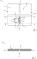
- the mover 16 can be driven and freely positioned in a floating state on the drive surface 14, compare Fig. 1 .
- the drive table 12 comprises a plurality of tile-shaped drive sections 18.
- the drive sections 18 are arranged such that adjacent drive sections 18 are separated from one another by a gap 20 with a fixed gap width 22, compare Fig. 1 and 2 .
- the mover 16 can be driven across the gap 20, the gap width 22 preferably being significantly smaller than a width 24 or length 26 of the mover 16.
- the width 22 of the gap 20 is not greater than 30% of the width 24 or the length 26 of the mover 16.
- the drive surface 14 has a working area 28.
- the mover 16 can implement different work functions, for example transporting goods to be transported and/or interacting with work tools (not shown).
- the drive surface 14 also has a cleaning area 30.
- the cleaning area 30 extends, for example, between two adjacent drive sections 18, in particular along a partial length of a gap 20 of the work surface 14.
- a Cleaning device 32 arranged with a cleaning unit 34, which delimits the cleaning area 30 in the direction of the drive surface 14.
- the cleaning device 32 has spray elements 36 oriented perpendicular to the drive surface 14 for spraying a cleaning medium, and also optionally a drain device 38. It is also conceivable to arrange one or more UV sources or a combination of spray elements 36 and UV sources on the cleaning unit 34 .
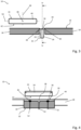
- the cleaning device 32 is used to clean at least part of an outer shell 40 of the mover 16, in particular an underside 42 of the mover 16 facing the drive surface, compare Fig. 3 .
- the cleaning unit 34 is arranged set back relative to the drive surface 14 of adjacent drive sections 18, the offset being compensated for by connecting profiles 44, the top sides of which are inclined relative to the drive surface 14.
- the mover 16 is moved from the working area 28 into the cleaning area 30 by the electromagnetic drive of the drive surface 14, and the underside 42 is applied with the cleaning medium by the spray elements 36.
- the mover 16 can stand still in the cleaning area 30 or move through the cleaning area 30 at a constant speed.
- the mover 16 - superimposed on the standstill or the constant movement - to have a rotational movement about its vertical axis 46 and/or oscillating movements about and/or along its transverse axis 48 and/or longitudinal axis 50 and/or or vertical axis 46 executes.
- Fig. 4 is a sectional view of the device 10 along the in Fig. 3 Section plane marked IV-IV shows.
- the spray elements 36 are connected via lines 52 to a cleaning medium reservoir (not shown) and preferably arranged in or on the drive table 12 and to a pump system and can preferably be actuated in groups or individually.
- the drain device 38 is designed, for example, as a centrally arranged, funnel-shaped recess in the cleaning unit 34. At its tapered end, the recess is connected to a drain line 54 running within the cleaning unit 34, whereby excess and returning cleaning medium, possibly containing dirt from the mover 16, can be removed from the drive surface 14.
- the additional cleaning units 56 are arranged on or above the drive surface 14 and form in turn, a limitation of the cleaning area 30.
- the additional cleaning units 56 are arranged in particular in such a way that simultaneous cleaning of the underside 42 as well as side surfaces 58 and/or a top side 60 of the mover 16 is possible.
- the additional cleaning units 56 also have spray elements 36 and lines 52.
- the cleaning unit 34 and/or the additional cleaning units 56 may include mechanical cleaning elements 62, for example brushes 64.
- the mover 16 is brought into contact with the mechanical cleaning elements 62 during and/or after exposure to the cleaning medium and is moved relative to the mechanical cleaning elements 62.
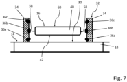
- Fig. 7 is another embodiment of the planar drive device 10 in one of Fig. 4 to 6 corresponding sectional view shown.
- the cleaning device 32 is not arranged in a gap between adjacent drive sections 18, but on or above the drive surface 14.
- the cleaning device 32 includes cleaning units 34 with spray elements 36a to 36c, which have different spray directions.
- the spray elements 36a to 36c are arranged at different distances from the drive surface 14 and are preferably at identical distances relative to one another.
- the cleaning units 34 have spray elements 36a arranged adjacent to the drive surface 14, which spray the cleaning medium away from the drive surface 14 in the direction of the underside 42 of the mover 16 arranged in the cleaning area 30.
- the cleaning units 34 have spray elements 36b which are further spaced apart from the drive surface 14 and which spray the cleaning medium in a direction parallel to the drive surface 14 onto the side surfaces 58 of the mover 16 arranged in the cleaning area 30.
- the cleaning units 34 have spray elements 36c which are further spaced apart from the drive surface 14 and which spray the cleaning medium in the direction of the drive surface onto the top side 60 of the mover 16 arranged in the cleaning area 30.
- the arrangement is also the same Fig. 7 possible to clean the entire outer shell 40 of the mover 16, with no cleaning units 34 having to be arranged below and/or above the drive surface 14 (i.e. different from the arrangements according to 5 and 6 ).
Landscapes
- Engineering & Computer Science (AREA)
- Health & Medical Sciences (AREA)
- Power Engineering (AREA)
- Chemical & Material Sciences (AREA)
- Combustion & Propulsion (AREA)
- Electromagnetism (AREA)
- Physics & Mathematics (AREA)
- Epidemiology (AREA)
- Life Sciences & Earth Sciences (AREA)
- Animal Behavior & Ethology (AREA)
- General Health & Medical Sciences (AREA)
- Public Health (AREA)
- Veterinary Medicine (AREA)
- Mechanical Engineering (AREA)
- Cleaning In General (AREA)
Applications Claiming Priority (1)
| Application Number | Priority Date | Filing Date | Title |
|---|---|---|---|
| DE102022118128.6A DE102022118128A1 (de) | 2022-07-20 | 2022-07-20 | Planarantriebsvorrichtung und Verfahren zum Betrieb einer Planarantriebsvorrichtung |
Publications (1)
| Publication Number | Publication Date |
|---|---|
| EP4310030A1 true EP4310030A1 (fr) | 2024-01-24 |
Family
ID=87158326
Family Applications (1)
| Application Number | Title | Priority Date | Filing Date |
|---|---|---|---|
| EP23183720.4A Pending EP4310030A1 (fr) | 2022-07-20 | 2023-07-05 | Dispositif d'entraînement planaire et procédé de fonctionnement d'un dispositif d'entraînement planaire |
Country Status (4)
| Country | Link |
|---|---|
| US (1) | US12311410B2 (fr) |
| EP (1) | EP4310030A1 (fr) |
| CN (1) | CN117458820A (fr) |
| DE (1) | DE102022118128A1 (fr) |
Cited By (1)
| Publication number | Priority date | Publication date | Assignee | Title |
|---|---|---|---|---|
| WO2026021764A1 (fr) | 2024-07-24 | 2026-01-29 | Bausch + Ströbel SE + Co. KG | Système de transport plan pour une installation de traitement de contenants pharmaceutiques, et installation comprenant un tel système de transport |
Families Citing this family (1)
| Publication number | Priority date | Publication date | Assignee | Title |
|---|---|---|---|---|
| CN118002525A (zh) * | 2024-02-26 | 2024-05-10 | 襄阳中车电机技术有限公司 | 一种永磁同步直线电机动子在线清扫装置 |
Citations (5)
| Publication number | Priority date | Publication date | Assignee | Title |
|---|---|---|---|---|
| US20170320682A1 (en) * | 2014-12-09 | 2017-11-09 | Robert Bosch Gmbh | Solenoid-Powered Conveying Device |
| DE102019117431A1 (de) | 2019-06-27 | 2020-12-31 | Beckhoff Automation Gmbh | Anordnung von Statormodulen für ein Planarantriebssystem |
| WO2022009476A1 (fr) * | 2020-07-10 | 2022-01-13 | 株式会社日立ハイテク | Dispositif porte-échantillon |
| US20220032477A2 (en) | 2017-03-27 | 2022-02-03 | Planar Motor Incorporated | Robotic devices and methods for fabrication, use and control of same |
| US20220131426A1 (en) * | 2019-06-27 | 2022-04-28 | Beckhoff Automation Gmbh | Assembly of stator modules for a planar drive system |
Family Cites Families (8)
| Publication number | Priority date | Publication date | Assignee | Title |
|---|---|---|---|---|
| US6445093B1 (en) * | 2000-06-26 | 2002-09-03 | Nikon Corporation | Planar motor with linear coil arrays |
| KR20140084238A (ko) * | 2011-10-27 | 2014-07-04 | 더 유니버시티 오브 브리티쉬 콜롬비아 | 변위 장치 및 변위 장치의 제조, 사용 그리고 제어를 위한 방법 |
| WO2015179962A1 (fr) | 2014-05-30 | 2015-12-03 | The University Of British Columbia | Dispositifs de déplacement et leurs procédés de fabrication, d'utilisation et de commande |
| DE102015209610A1 (de) | 2015-05-26 | 2016-12-01 | Robert Bosch Gmbh | Transportvorrichtung |
| US10654660B2 (en) * | 2018-01-31 | 2020-05-19 | Laitram, L.L.C. | Hygienic magnetic tray and conveyor |
| DE102019117430A1 (de) * | 2019-06-27 | 2020-12-31 | Beckhoff Automation Gmbh | Verfahren zum Bewegen eines Läufers in einem Planarantriebssystem |
| DE102022108188A1 (de) * | 2022-04-05 | 2023-10-05 | Syntegon Technology Gmbh | Planar-Antriebssystem und ein Verfahren zur Montage und Demontage von Statormodulen |
| WO2024148442A1 (fr) * | 2023-01-13 | 2024-07-18 | Planar Motor Incorporated | Dispositif de déplacement pour des systèmes de déplacement, et ses procédés et ses systèmes de fabrication et d'utilisation |
-
2022
- 2022-07-20 DE DE102022118128.6A patent/DE102022118128A1/de active Pending
-
2023
- 2023-07-05 EP EP23183720.4A patent/EP4310030A1/fr active Pending
- 2023-07-17 US US18/353,496 patent/US12311410B2/en active Active
- 2023-07-18 CN CN202310883359.7A patent/CN117458820A/zh active Pending
Patent Citations (5)
| Publication number | Priority date | Publication date | Assignee | Title |
|---|---|---|---|---|
| US20170320682A1 (en) * | 2014-12-09 | 2017-11-09 | Robert Bosch Gmbh | Solenoid-Powered Conveying Device |
| US20220032477A2 (en) | 2017-03-27 | 2022-02-03 | Planar Motor Incorporated | Robotic devices and methods for fabrication, use and control of same |
| DE102019117431A1 (de) | 2019-06-27 | 2020-12-31 | Beckhoff Automation Gmbh | Anordnung von Statormodulen für ein Planarantriebssystem |
| US20220131426A1 (en) * | 2019-06-27 | 2022-04-28 | Beckhoff Automation Gmbh | Assembly of stator modules for a planar drive system |
| WO2022009476A1 (fr) * | 2020-07-10 | 2022-01-13 | 株式会社日立ハイテク | Dispositif porte-échantillon |
Cited By (2)
| Publication number | Priority date | Publication date | Assignee | Title |
|---|---|---|---|---|
| WO2026021764A1 (fr) | 2024-07-24 | 2026-01-29 | Bausch + Ströbel SE + Co. KG | Système de transport plan pour une installation de traitement de contenants pharmaceutiques, et installation comprenant un tel système de transport |
| DE102024121092A1 (de) * | 2024-07-24 | 2026-01-29 | Bausch + Ströbel SE + Co. KG | Planares Transportsystem für eine Anlage zum Verarbeiten pharmazeutischer Behälter und Anlage mit einem derartigen Transportsystem |
Also Published As
| Publication number | Publication date |
|---|---|
| CN117458820A (zh) | 2024-01-26 |
| DE102022118128A1 (de) | 2024-01-25 |
| US12311410B2 (en) | 2025-05-27 |
| US20240025661A1 (en) | 2024-01-25 |
Similar Documents
| Publication | Publication Date | Title |
|---|---|---|
| EP4310030A1 (fr) | Dispositif d'entraînement planaire et procédé de fonctionnement d'un dispositif d'entraînement planaire | |
| DE69718007T2 (de) | Vorrichtung und verfahren zum reinigen von flexographischen druckplatten | |
| EP0782878A1 (fr) | Appareil de nettoyage | |
| EP0693378B1 (fr) | Appareil pour nettoyer des cylindres | |
| DE69610299T2 (de) | Verfahren und einrichtung zum behandeln von leiterplatten | |
| EP0160810B1 (fr) | Cabine pour revêtement par poudre | |
| DE102019104579A1 (de) | Druckmaschine | |
| WO2018137976A1 (fr) | Dispositif de nettoyage | |
| DE2823958A1 (de) | Verfahren und vorrichtung zur spritzbehandlung, insbesondere zum spritzlackieren von gegenstaenden | |
| DE60014488T2 (de) | Siebdruckvorrichtung mit einer Reinigungseinheit, die innerhalb eines Stencils ersetzbar ist | |
| EP4603199A1 (fr) | Installation de lavage de roues | |
| DE69503557T2 (de) | Verfahren und Einrichtung zur Reinigung von Ofenwagen | |
| DE2942268A1 (de) | Vorrichtung zur reinigung eines laufenden bandes | |
| DE19931305A1 (de) | Reinigungsvorrichtung für das Druckwerk einer Rotationsdruckmaschine | |
| EP4074425A1 (fr) | Nettoyeur de rouleau de pliage et procédé de nettoyage d'un tel rouleau de sertissage | |
| DE10216685A1 (de) | Vorrichtung und Verfahren zum Reinigen von Oberflächen | |
| EP1056550B1 (fr) | Tete de nettoyage d'un dispositif de nettoyage pour surface de fenetres et de facades | |
| DE20204460U1 (de) | Farbspritzanlage | |
| EP4316856B1 (fr) | Procédé de nettoyage permettant de nettoyer des faces de buse d'un ensemble têtes d'impression à jet d'encre | |
| DE60001010T2 (de) | Druckplattenwaschvorrichtung | |
| EP4349742B1 (fr) | Dispositif de nettoyage pour courroie de transport | |
| EP4035534B1 (fr) | Machine à traiter et/ou à fabriquer des denrées alimentaires | |
| DE102019104580A1 (de) | Druckmaschine | |
| DE102011011759A1 (de) | Magnetabscheidevorrichtung und Magnetabscheideverfahren zum Abscheiden von ferromagnetischen Teilchen aus einer damit belasteten Flüssigkeit | |
| EP3744225B1 (fr) | Appareil pour l'usinage de surfaces |
Legal Events
| Date | Code | Title | Description |
|---|---|---|---|
| PUAI | Public reference made under article 153(3) epc to a published international application that has entered the european phase |
Free format text: ORIGINAL CODE: 0009012 |
|
| STAA | Information on the status of an ep patent application or granted ep patent |
Free format text: STATUS: THE APPLICATION HAS BEEN PUBLISHED |
|
| AK | Designated contracting states |
Kind code of ref document: A1 Designated state(s): AL AT BE BG CH CY CZ DE DK EE ES FI FR GB GR HR HU IE IS IT LI LT LU LV MC ME MK MT NL NO PL PT RO RS SE SI SK SM TR |
|
| STAA | Information on the status of an ep patent application or granted ep patent |
Free format text: STATUS: REQUEST FOR EXAMINATION WAS MADE |
|
| 17P | Request for examination filed |
Effective date: 20240429 |
|
| RBV | Designated contracting states (corrected) |
Designated state(s): AL AT BE BG CH CY CZ DE DK EE ES FI FR GB GR HR HU IE IS IT LI LT LU LV MC ME MK MT NL NO PL PT RO RS SE SI SK SM TR |
|
| RAP3 | Party data changed (applicant data changed or rights of an application transferred) |
Owner name: SYNTEGON TECHNOLOGY GMBH |