EP4310042A1 - Dispositif de déploiement de bobines d'enroulement - Google Patents
Dispositif de déploiement de bobines d'enroulement Download PDFInfo
- Publication number
- EP4310042A1 EP4310042A1 EP22770674.4A EP22770674A EP4310042A1 EP 4310042 A1 EP4310042 A1 EP 4310042A1 EP 22770674 A EP22770674 A EP 22770674A EP 4310042 A1 EP4310042 A1 EP 4310042A1
- Authority
- EP
- European Patent Office
- Prior art keywords
- deployment device
- reel
- inner tube
- tube
- outer tube
- Prior art date
- Legal status (The legal status is an assumption and is not a legal conclusion. Google has not performed a legal analysis and makes no representation as to the accuracy of the status listed.)
- Pending
Links
Images


Classifications
-
- B—PERFORMING OPERATIONS; TRANSPORTING
- B65—CONVEYING; PACKING; STORING; HANDLING THIN OR FILAMENTARY MATERIAL
- B65H—HANDLING THIN OR FILAMENTARY MATERIAL, e.g. SHEETS, WEBS, CABLES
- B65H75/00—Storing webs, tapes, or filamentary material, e.g. on reels
- B65H75/02—Cores, formers, supports, or holders for coiled, wound, or folded material, e.g. reels, spindles, bobbins, cop tubes, cans, mandrels or chucks
- B65H75/34—Cores, formers, supports, or holders for coiled, wound, or folded material, e.g. reels, spindles, bobbins, cop tubes, cans, mandrels or chucks specially adapted or mounted for storing and repeatedly paying-out and re-storing lengths of material provided for particular purposes, e.g. anchored hoses, power cables
- B65H75/38—Cores, formers, supports, or holders for coiled, wound, or folded material, e.g. reels, spindles, bobbins, cop tubes, cans, mandrels or chucks specially adapted or mounted for storing and repeatedly paying-out and re-storing lengths of material provided for particular purposes, e.g. anchored hoses, power cables involving the use of a core or former internal to, and supporting, a stored package of material
- B65H75/40—Cores, formers, supports, or holders for coiled, wound, or folded material, e.g. reels, spindles, bobbins, cop tubes, cans, mandrels or chucks specially adapted or mounted for storing and repeatedly paying-out and re-storing lengths of material provided for particular purposes, e.g. anchored hoses, power cables involving the use of a core or former internal to, and supporting, a stored package of material mobile or transportable
-
- B—PERFORMING OPERATIONS; TRANSPORTING
- B65—CONVEYING; PACKING; STORING; HANDLING THIN OR FILAMENTARY MATERIAL
- B65H—HANDLING THIN OR FILAMENTARY MATERIAL, e.g. SHEETS, WEBS, CABLES
- B65H49/00—Unwinding or paying-out filamentary material; Supporting, storing or transporting packages from which filamentary material is to be withdrawn or paid-out
- B65H49/18—Methods or apparatus in which packages rotate
- B65H49/20—Package-supporting devices
- B65H49/32—Stands or frameworks
- B65H49/321—Stands or frameworks characterised by features enabling their folding or dismantling
-
- B—PERFORMING OPERATIONS; TRANSPORTING
- B65—CONVEYING; PACKING; STORING; HANDLING THIN OR FILAMENTARY MATERIAL
- B65H—HANDLING THIN OR FILAMENTARY MATERIAL, e.g. SHEETS, WEBS, CABLES
- B65H16/00—Unwinding, paying-out webs
- B65H16/02—Supporting web roll
- B65H16/06—Supporting web roll both-ends type
-
- B—PERFORMING OPERATIONS; TRANSPORTING
- B65—CONVEYING; PACKING; STORING; HANDLING THIN OR FILAMENTARY MATERIAL
- B65H—HANDLING THIN OR FILAMENTARY MATERIAL, e.g. SHEETS, WEBS, CABLES
- B65H49/00—Unwinding or paying-out filamentary material; Supporting, storing or transporting packages from which filamentary material is to be withdrawn or paid-out
- B65H49/18—Methods or apparatus in which packages rotate
- B65H49/20—Package-supporting devices
- B65H49/32—Stands or frameworks
- B65H49/324—Constructional details
-
- B—PERFORMING OPERATIONS; TRANSPORTING
- B65—CONVEYING; PACKING; STORING; HANDLING THIN OR FILAMENTARY MATERIAL
- B65H—HANDLING THIN OR FILAMENTARY MATERIAL, e.g. SHEETS, WEBS, CABLES
- B65H75/00—Storing webs, tapes, or filamentary material, e.g. on reels
- B65H75/02—Cores, formers, supports, or holders for coiled, wound, or folded material, e.g. reels, spindles, bobbins, cop tubes, cans, mandrels or chucks
- B65H75/34—Cores, formers, supports, or holders for coiled, wound, or folded material, e.g. reels, spindles, bobbins, cop tubes, cans, mandrels or chucks specially adapted or mounted for storing and repeatedly paying-out and re-storing lengths of material provided for particular purposes, e.g. anchored hoses, power cables
- B65H75/38—Cores, formers, supports, or holders for coiled, wound, or folded material, e.g. reels, spindles, bobbins, cop tubes, cans, mandrels or chucks specially adapted or mounted for storing and repeatedly paying-out and re-storing lengths of material provided for particular purposes, e.g. anchored hoses, power cables involving the use of a core or former internal to, and supporting, a stored package of material
- B65H75/44—Constructional details
- B65H75/4457—Arrangements of the frame or housing
- B65H75/446—Arrangements of the frame or housing for releasably or permanently attaching the frame to a wall, on a floor or on a post or the like
-
- B—PERFORMING OPERATIONS; TRANSPORTING
- B65—CONVEYING; PACKING; STORING; HANDLING THIN OR FILAMENTARY MATERIAL
- B65H—HANDLING THIN OR FILAMENTARY MATERIAL, e.g. SHEETS, WEBS, CABLES
- B65H75/00—Storing webs, tapes, or filamentary material, e.g. on reels
- B65H75/02—Cores, formers, supports, or holders for coiled, wound, or folded material, e.g. reels, spindles, bobbins, cop tubes, cans, mandrels or chucks
- B65H75/34—Cores, formers, supports, or holders for coiled, wound, or folded material, e.g. reels, spindles, bobbins, cop tubes, cans, mandrels or chucks specially adapted or mounted for storing and repeatedly paying-out and re-storing lengths of material provided for particular purposes, e.g. anchored hoses, power cables
- B65H75/38—Cores, formers, supports, or holders for coiled, wound, or folded material, e.g. reels, spindles, bobbins, cop tubes, cans, mandrels or chucks specially adapted or mounted for storing and repeatedly paying-out and re-storing lengths of material provided for particular purposes, e.g. anchored hoses, power cables involving the use of a core or former internal to, and supporting, a stored package of material
- B65H75/44—Constructional details
- B65H75/4457—Arrangements of the frame or housing
- B65H75/4465—Foldable or collapsible
-
- B—PERFORMING OPERATIONS; TRANSPORTING
- B65—CONVEYING; PACKING; STORING; HANDLING THIN OR FILAMENTARY MATERIAL
- B65H—HANDLING THIN OR FILAMENTARY MATERIAL, e.g. SHEETS, WEBS, CABLES
- B65H2701/00—Handled material; Storage means
- B65H2701/30—Handled filamentary material
- B65H2701/34—Handled filamentary material electric cords or electric power cables
Definitions
- the invention as expressed in the wording of the present specification, relates to a device for deploying cable reels, irrigation hoses, ropes or the like as elongated, flexible elements which are wound and unwound around a reel for storage, use and transport.
- extension reels also commonly known as extension reels or extension reels when the element to be wound is an electric cable
- extension reels also commonly known as extension reels or extension reels when the element to be wound is an electric cable
- the most widely used extensions are those of the type comprising a support structure consisting of a single folded tube which constitutes both the means of support for the reel and the handle for its transport. In this configuration the reel is practically level with the support surface on which it rests, which is normally the floor.
- extension pole is uncomfortable and cumbersome for the user, who, if he cannot find a raised surface on which to rest the extension pole, has to wind and unwind the cable in a crouched position.
- US Patent US6908058 relates to a trolley for hose storage reels comprising a remote reel handle mounted on top of the handle to allow rotation of the reel from an elevated position.
- the trolley or support structure provides a certain height for the remote crank that operates the cable rewind, so that it is conveniently accessible to the user, while the reel remains at a lower height.
- This distance between the crank and the reel results in a complex structure and a multitude of additional elements for its connection, which increases its cost, its size and makes it difficult to store and transport.
- document US20060138270 presents a portable cable station comprising a handlebar configured to move between an extended and a retracted position.
- This system in its extended position allows for convenient transport of the reel while in its retracted position it reduces the space occupied by the support structure. However, it does not provide height to the rewind reel, so that cable rewinding is performed from a position that is uncomfortable for the user.
- French patent FR2894236 relates to a system allowing the use and storage of a garden hose. It features a variable geometry that allows two positions of use of the system, at different heights, thanks to a mobile section that can pivot in relation to the ground support and lock with a ratchet mechanism (5a, 5b) and handwheel (6a, 6b) with the hose reel in upper or lower positions.
- a ratchet mechanism (5a, 5b) and handwheel (6a, 6b) with the hose reel in upper or lower positions.
- the tilting means allow only two positions of the reel, this solution not being adaptable to different users and different heights.
- the structure includes a multitude of tubes that make it more expensive and would take up even more space if the reel were to be raised to a height of 80 or 90 cm from the ground, where the handling of the cable is more comfortable for the operator.
- the deployment device for winding reels of the present invention solves the problems of the prior art as it provides a deployable support means that raises the reel of reels to different adjustable heights, thus adapting to each user, all without compromising the size or complexity of the assembly and without increasing its cost.
- a device is achieved that not only adds height to the reel with the advantages of safety, stability, balance and comfort that this entails, but it is also retractable, thus reducing its size for easy storage and transport.
- the deployment device for winding reels of the present invention comprises:
- the extensible linking means between the support base and the reel make it possible, in an extended or partially extended position, to raise the reel to different heights in an adjustable manner and, in a retracted position, to reduce the size of the deployment device.
- the extensible linking means are constituted with at least one outer tube (1) and at least one inner tube (2) of smaller cross-section than the outer tube (1), configured in such a way as to allow relative movement between them.
- the inner tube (2) can move inside the outer tube (1) in its axial or longitudinal direction, i.e. the inner tube (2) can be pushed in or pulled out of the outer tube (1).
- the length comprising the inner tube (2) is inserted completely inside the outer tube (1), not being visible from the outside, as in figures 1 and 2 .
- the inner tube (2) In an extended position of the deployment device, the inner tube (2) is at least partially outside the outer tube (1), so that the length of inner tube (2) outside the outer tube (1) is proportional to the elevation of the reel (7).
- the linking means comprise a plurality of outer tubes (1), at least one of which has a curvature that allows the geometry of the device to be modified.
- the inner tubes (2) are straight.
- the final configuration of the deployment device is achieved by inserting the first end of a first inner tube (2) into an end of a first outer tube (1), and the second end of the first inner tube (2) into an end of a second outer tube (1).
- the outer tubes (1) are positioned next to each other as in figures 1 or 2 , whereas when the deployment device is in its extended position, two outer tubes (1) which in retracted position were contiguous are now separated by an inner tube (2) as in figure 3 .
- the geometry adopted by the outer tubes (1) that make up the deployment device must be such as to provide the necessary stability to the assembly when it is in its extended position ( Figure 3 ), as well as to take up as little space as possible when it is in its retracted position ( Figure 1 ).
- the means constituting the support base of the deployment device can be configured with an outer tube (1) comprising two curved sections or folds so that its geometry presents two parallel and opposite sides (1a) joined together by a third side, as can be seen in more detail in figure 2 .
- This outer tube (1) which forms the support base of the deployment device, can be further subdivided into several sections of outer tubes (1) containing inside them extensible inner tubes (2) that allow to increase their length, as shown in figure 3 .
- the outer tube (1) that forms the support base of the deployment device has a free end, while attached to its other end there is a succession of outer tubes (1), also folded, which house the corresponding inner tubes (2), so that together they form the extensible linking means between the support base (13) and the support means of the reel (7).
- the geometry of the outer tubes (2) must be such as to provide the deployment device with the necessary rigidity so that the operation of the winding (8), normally operated by means of a hand crank (9), does not destabilise the system.
- a first outer tube (1d) adjacent to the support means of the reel (7) is arranged inclined with a vertical component, thus preventing the forces transmitted to the reel (7) by the user when winding and unwinding the winding (8) from creating moments of force that destabilise the deployment device.
- the deployment device may comprise an anchoring system (5) as a connecting system between an inner tube (2) and an outer tube (1), which allows the axial position of the inner tube (2) within the outer tube (1) to be adjusted.
- the anchoring system (5) prevents axial displacement of the inner tube (2) within the outer tube (1), while in another position it allows such displacement.
- the anchoring system (5) is capable of fixing the axial position of the inner tube (2) within the outer tube (1).
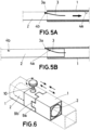
- the anchoring system (5) comprises the following elements according to Figures 5a and 5b :
- the distance between the recess (4a,4b) is the maximum length of inner tube (2) that can be safely and securely anchored outside the outer tube (1).
- a plurality of extended tube locking recess (4a) can be provided along the surface of the inner tube (2).
- the strap (3) is free and tension-free protruding from one end of the outer tube (2) (see figure 5b ). As the inner tube (2) advances or retracts, the strap (3) slides along the outer surface of the inner tube (2) unopposed.
- the protrusion (3a) of the strap (3) is inserted into the extended tube locking recess (4a), thus anchoring it and preventing further advance of the inner tube (2). In this position, the strap (3) is tensioned.
- the anchoring system (5) is not limited to the one described above, but it is possible to use another system that achieves the desired effect of locking the extension or retraction of an inner tube (2) inside an outer tube (1) in an adjustable manner.
- the anchoring system (5) may comprise a plurality of retractable bosses arranged on the side surface of the inner tube (2) capable of being inserted into a plurality of holes of the same shape formed in the outer tube (1), thus anchoring the assembly.
- an outer tube (1) and an inner tube (2) consisting of a tilting and anchoring mechanism (6).
- This mechanism allows not only to regulate the advance or retreat of the inner tube (2) inside the outer tube (1) in longitudinal direction, but also to regulate the rotation of the inner tube (2) around an axis defined by its longitudinal direction.
- the tilting and anchoring mechanism (6) is capable of fixing the angular and axial position of the inner tube (2) within the outer tube (1).
- the rotation allows the set of tubes (1,2) attached to one end of the rotating inner tube (2) to tilt relative to the outer tube (1) which houses the inner tube (2), ultimately allowing the deployment device to be more compact and occupy less space in its retracted arrangement.
- a possible embodiment of the tilting and anchoring mechanism (6), shown in Figure 6 may comprise:
- both the inner tube (2) and the outer tube (1) are free to rotate with respect to the other outer tube (1).
- the tilting and anchoring mechanism (6) may comprise, instead of a clamping screw (10), a pin that diametrically crosses both the side surfaces of the outer tube (1) and the inner tube (2).
- a third type of joint between an outer tube (1) and an inner tube (2) is the end-welded joint.
- the deployment device comprises a single joint based on the tilting and anchoring mechanism (6), while the remaining joints are made either by means of anchoring systems (5a,5b), which do not allow relative rotation between tubes, or by means of welded joints.
- anchoring systems (5a,5b)
- the present invention is not limited to this configuration.
- Figure 3 refers to the deployment device in its fully extended position, for which the reel (7) reaches a higher elevation.
- a first anchoring system (5b) is loosened so that a first inner tube (2b) is inserted inside a first outer tube (1d), this is the deployment device is retracted and the reel (7) reduces its height with respect to the support base (13).
- a second anchoring system (5a) is then loosened so that a second inner tube (2a) is inserted into a second outer tube (1b).
- the inner tubes (2) forming the support base are also retracted.
- the tilting and anchoring mechanism (6) is loosened and a second outer tube (1c) is rotated relative to a third outer tube (1b).
- the reel (7) tilts relative to the second outer tube (1c) until it occupies a position that is not elevated relative to the support base of the deployment device, as shown in Figure 1 .
- the different outer tubes (1) and inner tubes (2) that make up the deployment device are independent and separable from each other, it is possible to separate, for example, the following set of tubes from the rest of the deployment device: the first outer tube (1d) which is attached to the reel (7), a first inner tube (2b), the second outer tube (1c) and a third inner tube (2c).
- This provides a support structure of the reel (7) that can be suspended from surfaces comprising an overhang, such as window frames or scaffolding, via the third inner tube (2c) as shown in figure 4 .
- This functionality is very useful for an operator working on different types of surfaces as it is not necessary to unwind as much cable, but the extension pole itself can be brought close to any difficult to access operating surface that is elevated.
- the device described here has low manufacturing costs, as it is assembled in a simple way and using a small number of components.
- inner tubes (2) and outer tubes (1) can be disassembled, which even makes it possible to store the different elements separately and then assemble them.
- the extensible linking means are constituted with telescopic members (12).
- the telescopic members (12) may comprise a plurality of tubes of variable cross-section mounted within each other in an axially sliding manner, so that the inner tubes can be pulled out or pushed into the outer tubes in a controlled manner.
- the telescopic members (12) comprise locking means that allow, as an inner tube extends out of an outer tube, to anchor the position of the inner tube within the outer tube at different heights.
- the deployment device further comprises a support base (13), which can be stepped on by the user when extending the telescopic members (12) to ensure the stability of the assembly.
- the support means of the reel (7) may comprise a support element (16) attached to the inner tube defining the upper end of the telescopic members (12).
- the deployment device comprises a folded tube with one of its sides arranged parallel to the support base (13) which acts as a handle (14) to pull to extend the telescopic members (12).
- the extensible linking means are constituted with a accordion-type deployable structure (15).
- the deployable structure (15) comprises a single type accordion
- the deployable structure (15) comprises a double type accordion.
- the deployment device comprises a support base (13) that can be stepped on by the user when extending the deployable structure (15) to ensure the stability of the assembly, one of the ends of the deployable structure (15) constituting the connection to the support base (13), and another of its ends constituting the support means of the reel (7).
- the initial elongation (15a) and the final elongation (15b) of the accordion comprise a length substantially equal to half the length of the intermediate elongations (15c), so that when the deployable structure (15) is fully deployed, the reel (7) is substantially centred with the support base (13) .
- a possible embodiment of the invention is one in which the support base (13) comprises two telescopic sections that improve the stability of the assembly by covering a larger support surface.
- This will be particularly useful in cases where the winding (8), either because of its length or the material used in its manufacture, has a high weight.
- the winding (8) either because of its length or the material used in its manufacture, has a high weight.
- it will be of even greater interest in cases such as those described above and shown in figures 8a and 8b , since the greater the height, the more the stability of the assembly will be compromised.
- FIG. 9 Another possible embodiment of the invention is one in which the device incorporates a grip handle (17), for example as shown in the detail shown in Figure 9 , which is capable of being slidably attached to either of the outer tubes (1), although in the example shown in the figure it is attached to the second outer tube (1c).
- a grip handle (17) for example as shown in the detail shown in Figure 9 , which is capable of being slidably attached to either of the outer tubes (1), although in the example shown in the figure it is attached to the second outer tube (1c).
- a guiding system for the elongated flexible element is considered. This is a system that guides the flexible element during winding, so that the flexible element is evenly distributed over the entire surface of the reel (7) and does not pile up on one side or the other of the reel.
- the guiding system may consist of a worm screw through which an elongated flexible element carrier medium is moved axially and which moves forwards or backwards in its movement when the reel (7) is rotated in either direction, while the worm remains static.
Landscapes
- Storing, Repeated Paying-Out, And Re-Storing Of Elongated Articles (AREA)
- Manufacture Of Motors, Generators (AREA)
- Replacing, Conveying, And Pick-Finding For Filamentary Materials (AREA)
Applications Claiming Priority (2)
| Application Number | Priority Date | Filing Date | Title |
|---|---|---|---|
| ES202130239A ES2924299B2 (es) | 2021-03-18 | 2021-03-18 | Dispositivo de despliegue de carretes de arrollamiento |
| PCT/ES2022/070153 WO2022195150A1 (fr) | 2021-03-18 | 2022-03-17 | Dispositif de déploiement de bobines d'enroulement |
Publications (2)
| Publication Number | Publication Date |
|---|---|
| EP4310042A1 true EP4310042A1 (fr) | 2024-01-24 |
| EP4310042A4 EP4310042A4 (fr) | 2025-04-02 |
Family
ID=83319891
Family Applications (1)
| Application Number | Title | Priority Date | Filing Date |
|---|---|---|---|
| EP22770674.4A Pending EP4310042A4 (fr) | 2021-03-18 | 2022-03-17 | Dispositif de déploiement de bobines d'enroulement |
Country Status (5)
| Country | Link |
|---|---|
| US (1) | US12583708B2 (fr) |
| EP (1) | EP4310042A4 (fr) |
| CN (1) | CN117677575A (fr) |
| ES (1) | ES2924299B2 (fr) |
| WO (1) | WO2022195150A1 (fr) |
Families Citing this family (1)
| Publication number | Priority date | Publication date | Assignee | Title |
|---|---|---|---|---|
| ES2924299B2 (es) | 2021-03-18 | 2023-02-24 | Brico Color S L | Dispositivo de despliegue de carretes de arrollamiento |
Family Cites Families (17)
| Publication number | Priority date | Publication date | Assignee | Title |
|---|---|---|---|---|
| US2155773A (en) * | 1936-08-04 | 1939-04-25 | Signode Steel Strapping Co | Strap holding and guiding clip |
| US3304060A (en) * | 1965-02-11 | 1967-02-14 | Bea Wanless | Reel lift |
| US3833997A (en) * | 1973-08-20 | 1974-09-10 | S Kaddatz | Spool mounting tool |
| US4705283A (en) * | 1985-03-15 | 1987-11-10 | Kleisath Stanley N | Electricians wire spool carrier |
| US5179972A (en) * | 1991-02-21 | 1993-01-19 | Eley John H | Hose reel |
| US5109882A (en) * | 1991-02-21 | 1992-05-05 | Eley John H | Hose reel |
| US5316232A (en) * | 1992-11-13 | 1994-05-31 | Lambert Jr John A | Omnidirectional wire dispenser |
| US5330121A (en) * | 1993-04-12 | 1994-07-19 | Eley John H | Support bracket for hose reels |
| US6908058B2 (en) | 2003-03-28 | 2005-06-21 | Suncast Corporation | Hose reel cart with elevated crank handle |
| US20060138270A1 (en) | 2004-12-29 | 2006-06-29 | Fiskars Brands, Inc. | Portable cord station |
| FR2894236B1 (fr) | 2005-12-07 | 2009-04-24 | Mermier Lemarchand Soc Par Act | Chariot devidoir de tuyau admettant une position haute et une position basse |
| US20090038864A1 (en) * | 2007-08-07 | 2009-02-12 | Sung Yol Yun | Remotely controllable golf cart and method for steering a cart |
| US8727361B2 (en) * | 2011-01-06 | 2014-05-20 | Itool Equipment Holding Llc | Dolly for supporting a spool carrying a windable material |
| US9187289B1 (en) * | 2012-05-03 | 2015-11-17 | Itool Equipment Holding Llc | Apparatus for lifting and supporting an item for holding windable material |
| WO2016046852A1 (fr) * | 2014-09-23 | 2016-03-31 | Futura S.P.A. | Procédé de manipulation de bobines mères dans des usines de conversion de papier |
| US10272935B1 (en) * | 2016-09-08 | 2019-04-30 | Itool Equipment Holding Llc | Hand cart for lifting and supporting an item for holding windable material and associated method |
| ES2924299B2 (es) | 2021-03-18 | 2023-02-24 | Brico Color S L | Dispositivo de despliegue de carretes de arrollamiento |
-
2021
- 2021-03-18 ES ES202130239A patent/ES2924299B2/es active Active
-
2022
- 2022-03-17 EP EP22770674.4A patent/EP4310042A4/fr active Pending
- 2022-03-17 US US18/282,720 patent/US12583708B2/en active Active
- 2022-03-17 WO PCT/ES2022/070153 patent/WO2022195150A1/fr not_active Ceased
- 2022-03-17 CN CN202280031146.5A patent/CN117677575A/zh active Pending
Also Published As
| Publication number | Publication date |
|---|---|
| WO2022195150A1 (fr) | 2022-09-22 |
| US12583708B2 (en) | 2026-03-24 |
| CN117677575A (zh) | 2024-03-08 |
| US20240158200A1 (en) | 2024-05-16 |
| ES2924299B2 (es) | 2023-02-24 |
| ES2924299A1 (es) | 2022-10-05 |
| EP4310042A4 (fr) | 2025-04-02 |
Similar Documents
| Publication | Publication Date | Title |
|---|---|---|
| EP1069844B1 (fr) | Parasol avec support lateral pour l'inclinaison et l'ouverture | |
| EP2845510B1 (fr) | Parasol en porte-à-faux | |
| US4606366A (en) | Protective shelter, such as an umbrella with offset support | |
| US7886755B2 (en) | Side-supporting sunshade | |
| EP0763160B1 (fr) | Structure demontable | |
| CN101091036B (zh) | 覆盖系统 | |
| US4530389A (en) | Retractable awning with improved set-up capability | |
| EP0387965A1 (fr) | Parapluie pliant | |
| US20020023727A1 (en) | Rear window shade | |
| WO2003083244A1 (fr) | Frein unidirectionnel pour store sans cordon | |
| US20230313605A1 (en) | Window shade and actuating system thereof | |
| EP4310042A1 (fr) | Dispositif de déploiement de bobines d'enroulement | |
| AU2016262758A1 (en) | Height-adjustable table | |
| KR101281774B1 (ko) | 커버링 시스템 | |
| WO1992013788A1 (fr) | Appareil d'enroulement de tuyaux d'incendie et procede d'utilisation | |
| US7480448B2 (en) | Rapidly changeable photographic and stage backdrop lifting device | |
| US20050145739A1 (en) | Elongate material management apparatus | |
| US11969873B2 (en) | Automatic extending device | |
| CN214477861U (zh) | 一种用于单兵操作的大承载便携式复合材料支撑装置 | |
| EP1701907A1 (fr) | Grue de camera | |
| CN112787068B (zh) | 一种用于单兵操作的大承载便携式复合材料支撑装置 | |
| CN224104210U (zh) | 一种盒式收纳的电动车遮阳挡雨装置 | |
| CN223919466U (zh) | 一种隐藏收纳式的电动车遮阳挡雨装置 | |
| GB2332698A (en) | Collapsible ladder | |
| CN120589090A (zh) | 一种多功能水泵搬运车 |
Legal Events
| Date | Code | Title | Description |
|---|---|---|---|
| STAA | Information on the status of an ep patent application or granted ep patent |
Free format text: STATUS: THE INTERNATIONAL PUBLICATION HAS BEEN MADE |
|
| PUAI | Public reference made under article 153(3) epc to a published international application that has entered the european phase |
Free format text: ORIGINAL CODE: 0009012 |
|
| STAA | Information on the status of an ep patent application or granted ep patent |
Free format text: STATUS: REQUEST FOR EXAMINATION WAS MADE |
|
| 17P | Request for examination filed |
Effective date: 20230920 |
|
| AK | Designated contracting states |
Kind code of ref document: A1 Designated state(s): AL AT BE BG CH CY CZ DE DK EE ES FI FR GB GR HR HU IE IS IT LI LT LU LV MC MK MT NL NO PL PT RO RS SE SI SK SM TR |
|
| DAV | Request for validation of the european patent (deleted) | ||
| DAX | Request for extension of the european patent (deleted) | ||
| A4 | Supplementary search report drawn up and despatched |
Effective date: 20250227 |
|
| RIC1 | Information provided on ipc code assigned before grant |
Ipc: B65H 75/40 20060101ALI20250221BHEP Ipc: B65H 75/44 20060101ALI20250221BHEP Ipc: B65H 49/32 20060101AFI20250221BHEP |