EP4310048B1 - Vorrichtung zum füllen eines behälters und verfahren zum betreiben der vorrichtung - Google Patents
Vorrichtung zum füllen eines behälters und verfahren zum betreiben der vorrichtung Download PDFInfo
- Publication number
- EP4310048B1 EP4310048B1 EP23182968.0A EP23182968A EP4310048B1 EP 4310048 B1 EP4310048 B1 EP 4310048B1 EP 23182968 A EP23182968 A EP 23182968A EP 4310048 B1 EP4310048 B1 EP 4310048B1
- Authority
- EP
- European Patent Office
- Prior art keywords
- piston
- valve member
- valve
- electric drive
- filling
- Prior art date
- Legal status (The legal status is an assumption and is not a legal conclusion. Google has not performed a legal analysis and makes no representation as to the accuracy of the status listed.)
- Active
Links
Images


Classifications
-
- B—PERFORMING OPERATIONS; TRANSPORTING
- B67—OPENING, CLOSING OR CLEANING BOTTLES, JARS OR SIMILAR CONTAINERS; LIQUID HANDLING
- B67C—CLEANING, FILLING WITH LIQUIDS OR SEMILIQUIDS, OR EMPTYING, OF BOTTLES, JARS, CANS, CASKS, BARRELS, OR SIMILAR CONTAINERS, NOT OTHERWISE PROVIDED FOR; FUNNELS
- B67C3/00—Bottling liquids or semiliquids; Filling jars or cans with liquids or semiliquids using bottling or like apparatus; Filling casks or barrels with liquids or semiliquids
- B67C3/02—Bottling liquids or semiliquids; Filling jars or cans with liquids or semiliquids using bottling or like apparatus
- B67C3/22—Details
- B67C3/28—Flow-control devices, e.g. using valves
- B67C3/286—Flow-control devices, e.g. using valves related to flow rate control, i.e. controlling slow and fast filling phases
-
- B—PERFORMING OPERATIONS; TRANSPORTING
- B65—CONVEYING; PACKING; STORING; HANDLING THIN OR FILAMENTARY MATERIAL
- B65B—MACHINES, APPARATUS OR DEVICES FOR, OR METHODS OF, PACKAGING ARTICLES OR MATERIALS; UNPACKING
- B65B3/00—Packaging plastic material, semiliquids, liquids or mixed solids and liquids, in individual containers or receptacles, e.g. bags, sacks, boxes, cartons, cans, or jars
-
- B—PERFORMING OPERATIONS; TRANSPORTING
- B67—OPENING, CLOSING OR CLEANING BOTTLES, JARS OR SIMILAR CONTAINERS; LIQUID HANDLING
- B67C—CLEANING, FILLING WITH LIQUIDS OR SEMILIQUIDS, OR EMPTYING, OF BOTTLES, JARS, CANS, CASKS, BARRELS, OR SIMILAR CONTAINERS, NOT OTHERWISE PROVIDED FOR; FUNNELS
- B67C3/00—Bottling liquids or semiliquids; Filling jars or cans with liquids or semiliquids using bottling or like apparatus; Filling casks or barrels with liquids or semiliquids
- B67C3/02—Bottling liquids or semiliquids; Filling jars or cans with liquids or semiliquids using bottling or like apparatus
- B67C3/22—Details
- B67C3/26—Filling-heads; Means for engaging filling-heads with bottle necks
-
- B—PERFORMING OPERATIONS; TRANSPORTING
- B67—OPENING, CLOSING OR CLEANING BOTTLES, JARS OR SIMILAR CONTAINERS; LIQUID HANDLING
- B67C—CLEANING, FILLING WITH LIQUIDS OR SEMILIQUIDS, OR EMPTYING, OF BOTTLES, JARS, CANS, CASKS, BARRELS, OR SIMILAR CONTAINERS, NOT OTHERWISE PROVIDED FOR; FUNNELS
- B67C3/00—Bottling liquids or semiliquids; Filling jars or cans with liquids or semiliquids using bottling or like apparatus; Filling casks or barrels with liquids or semiliquids
- B67C3/02—Bottling liquids or semiliquids; Filling jars or cans with liquids or semiliquids using bottling or like apparatus
- B67C3/22—Details
- B67C3/28—Flow-control devices, e.g. using valves
Definitions
- the invention relates to a device for filling a container, a filler with several devices for filling and a method for operating a device for filling.
- Filling systems for filling a filling material into containers can include a filler for filling the containers.
- the filler can have at least one filling station or device for filling the containers.
- the device can have a throttle valve for adjusting a flow rate during filling and a filling valve downstream of the throttle valve for delivering the filling material to the container.
- the throttle valve can be controlled pneumatically or by an electric motor, for example.
- the WO 2018/141558 A1 describes a device for filling liquid or flowable contents into packaging, comprising a tank, a filling device with a filling valve, a line that connects the tank to the filling device and a throttle valve that is arranged in the line between the tank and the filling device.
- the throttle valve has a variable flow cross-section.
- the throttle valve has an actuator for adjusting the flow cross-section.
- the actuator serves to change the valve position and can, for example, comprise a pneumatic actuation unit.
- the EP 3581542 A1 discloses a device according to the preamble of claim 1.
- a disadvantage of a pneumatic actuator for a throttle valve can be that in practical applications it is restricted to a limited number of positions that can be reached when precise, reproducible accuracy is required.
- An electric actuator can be disadvantageous in that it is not suitable for a filling material with pulp, pieces, etc. due to a small valve element travel or stroke and it only closes relatively slowly.
- the invention is based on the object of creating an improved device for filling a container, with which the disadvantages mentioned can preferably be overcome at least in part.
- the device should be able to fill both pulp-containing (piece-containing/fiber-containing) liquid filling materials and pulp-free (piece-free/fiber-free) liquid filling materials, e.g. still or carbonated, without compromising on filling speed.
- the device for filling a container (e.g. filling station for a filler).
- the device has a filling valve for discharging a (e.g. liquid or pasty) filling material into the container (e.g. in a state pressed against a container mouth of the container).
- the device has a throttle valve for adjusting a flow rate of the filling material, wherein the throttle valve is arranged upstream of the filling valve.
- the throttle valve has a valve member for adjusting a flow cross section of the throttle valve.
- the throttle valve has a pneumatic drive which is operatively connected to the valve member for moving the valve member.
- the throttle valve has an electric drive which is operatively connected to the valve member for moving the valve member.
- the device can advantageously make it possible to combine the advantages of an electrical control of the throttle valve and the advantages of a pneumatic control of the throttle valve.
- the electric drive can be used, for example, to adjust the flow rate for clear filling materials or products without pulp, fibers, or pieces.
- a closing function e.g. to completely or partially close the throttle valve
- the pneumatic drive can be used particularly advantageously to support the power of the electric drive, e.g. for carbonized filling materials with increased filling pressure. This can advantageously make it possible to install a less powerful electric drive that requires less installation space and is more cost-effective.
- the lower power consumption can also be particularly advantageous because, for example, less power has to be transmitted to a rotating part of a rotary filler, which also means that a less complex slip ring transformer or similar can be provided.
- the pneumatic drive can be a pneumatic cylinder-piston drive.
- the electric drive can be an electromechanical, electromotoric, electromagnetic or piezoelectric drive, e.g. a stepper motor.
- the pneumatic drive e.g. a piston and/or a pressure chamber of the pneumatic drive
- the pneumatic drive can thus advantageously be operated on the one hand alone and on the other hand in combination with the electric drive to move the valve member.
- the pneumatic drive and the electric drive can be decoupled from one another and coupled to one another.
- the valve member can only be moved by the pneumatic drive and not by the electric drive, e.g. for the closing function.
- the coupling can enable the electric drive and the pneumatic drive to operate together, e.g. to relieve the load on the electric drive.
- the pneumatic drive has a pressure chamber that can be pressurized with compressed air and a piston (e.g. one-piece or multi-piece) in operative connection between the valve member and the pressure chamber.
- the piston of the pneumatic drive can preferably limit the pressure chamber. This can advantageously enable a reliable implementation of the pneumatic drive, which can advantageously be connected to the electric drive, for example to operate both drives in combination or to operate only the pneumatic drive.
- the piston of the pneumatic drive can be moved independently of the electric drive. In this way, a movement of the valve member can advantageously be brought about by operating only the pneumatic drive.
- the piston of the pneumatic drive can be pushed and/or supported by the electric drive. In this way, a movement of the valve member can advantageously be brought about by operating the pneumatic drive and the electric drive together or only by operating the electric drive.
- the electric drive has a piston that can preferably be moved by a spindle nut of the electric drive. This can advantageously enable a reliable implementation of the electric drive, which can advantageously be connected to the pneumatic drive in order to operate both drives in combination, for example, or to operate only the electric drive.
- the piston of the electric drive can be brought into operative connection, preferably into physical contact, with the piston of the pneumatic drive for pushing and/or supporting the piston of the pneumatic drive.
- the piston of the pneumatic drive and the piston of the electric drive have opposing contact surfaces for mutual contact.
- the valve member and the piston of the electric drive are arranged at opposite ends of the piston of the pneumatic drive. This can advantageously provide a reliable and simple construction for fulfilling the functions explained.
- the piston of the pneumatic drive can be moved independently of the piston of the electric drive.
- the piston of the pneumatic drive can be pushed and/or supported by the piston of the electric drive.
- the piston of the electric drive can be moved in the pressure chamber. This can also advantageously provide a reliable and simple construction for fulfilling the functions explained.
- the device further comprises a control device that is configured to operate the throttle valve in different operating modes.
- the operating modes can preferably comprise a pure pneumatic drive operating mode in which only the pneumatic drive is operated to move the valve member and/or to hold a position of the valve member, preferably to close the throttle valve (e.g. to assume the closed position or the partially open position).
- the operating modes can preferably comprise a pure electric drive operating mode in which only the electric drive is operated to move the valve member and/or to hold a position of the valve member, preferably to finely adjust the flow cross-section.
- the operating modes can preferably comprise a combination operating mode in which both the pneumatic drive and the electric drive are operated to move the valve member and/or to hold a position of the valve member, preferably simultaneously.
- a control pressure of the pneumatic drive can be adjustable for the combination operating mode.
- the control pressure is usually 5-6 bar.
- the control pressure can be adjustable from 0 bar to max.
- control device can refer to an electronic device (e.g. implemented as a driver circuit or with microprocessors and data storage) and/or a mechanical, pneumatic and/or hydraulic control, which, depending on the design, can take on control tasks and/or regulation tasks and/or processing tasks. Even if the term “control” is used here, it can also appropriately include or mean “regulation” or “control with feedback” and/or “processing”.
- the valve member has a passage channel, preferably a notch, for allowing a filling material (e.g. containing pulp, fibers or pieces, liquid) to pass through (e.g. at low flow rates), preferably in a partially open position of the throttle valve, in which the throttle valve can essentially only pass through the passage channel.
- a filling material e.g. containing pulp, fibers or pieces, liquid
- the passage channel can have the advantage that small pulps, fibers, etc. have a larger cross-section available at low flow rates, thus reducing the risk of blockage.
- valve element is screwed onto a piston of the pneumatic drive.
- the throttle valve has a return spring which prestresses the valve member in the direction of an open position or a closed position and which is preferably arranged coaxially to a piston of the pneumatic drive.
- the throttle valve can have a bellows for sealing between the valve member and a valve housing of the throttle valve, which is preferably arranged coaxially to a piston of the pneumatic drive.
- the throttle valve is designed as an angle seat valve.
- the angle seat valve can advantageously be a through valve with comparatively low flow resistance and a comparatively small deflection of a filling material flow. In this case, the angle seat valve can offer a good compromise between the requirements for the flow characteristics, the valve tightness and the required installation space.
- the device further comprises a static throttle arranged upstream of the throttle valve and/or a flow measuring device arranged upstream of the filling valve and upstream or downstream of the throttle valve.
- the static throttle can provide a flow cross-section required for filling pulp-containing/piece-containing/fiber-containing filling materials.
- the flow cross-section provided by the static throttle can be designed to be comparatively large and thus allow higher flow speeds for non-critical (pulp-free/piece-free/fiber-free) filling materials.
- the flow rate of the filling material can advantageously be measured using the flow measuring device.
- a control device can, for example, operate the throttle valve and/or the filling valve (for example, opening and/or closing) and/or adjust the operation of the throttle valve and/or the filling valve (for example, opening duration and/or opening width).
- a further aspect of the present disclosure relates to a filler, preferably a rotary filler or a linear filler, having a plurality of devices for filling as disclosed herein.
- a filler preferably a rotary filler or a linear filler, having a plurality of devices for filling as disclosed herein.
- the same advantages can be achieved with the filler as have already been explained with reference to the device for filling.
- the filler can be included in a container treatment plant for producing, cleaning, coating, testing, filling, closing, labelling, printing and/or packaging containers for liquid media, preferably beverages or liquid foodstuffs.
- the containers can be designed as bottles, cans, canisters, cartons, flacons, etc.
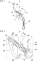
- the Figure 1 shows a device 10 for filling a container.
- the device 10 can fill the container with a liquid or pasty filling material, possibly with pieces, pulp or fibers.
- the filling material can be a beverage.
- a filler of a container treatment plant can have several of the devices 10.
- the filler can be designed as a rotary filler or a filler carousel with several devices 10 arranged around a circumference of the rotary filler.
- the filler can be designed, for example, as a linear filler with several devices 10 arranged next to one another and/or one behind the other. arranged devices 10.
- the filler can preferably fill several containers simultaneously or with temporal overlap by means of the several devices 10.
- the filler can be arranged downstream of a cleaning device for cleaning the containers and/or a manufacturing device for manufacturing the containers.
- the filler can be arranged upstream of a sealer for sealing the containers.
- the device 10 has a filling valve 12 and a throttle valve 18.
- the device 10 can have a static throttle 14 and/or a flow measuring device 16.
- the filling valve 12 serves to discharge the filling material from the device 10 into a container.
- the container is preferably positioned below the filling valve 12.
- the container can be pressed with its container mouth against the filling valve 12, for example for aseptic filling and/or pressure filling.
- the pressing can be achieved, for example, by a lifting device that enables a vertical movement of the filling valve 12 and/or the container.
- the filling valve 12 can be the last or most downstream valve of the device 10 with respect to a flow direction of the filling material.
- the filling valve 12 can receive the filling material after the filling material has flowed through or passed the throttle valve 18 and optionally the static throttle 14 and/or the flow measuring device 16.
- a fluid line can connect the filling valve 12 and the flow measuring device 16 and/or the throttle valve 18 to one another.
- the filling valve 12 can be actuated in any way.
- the filling valve 12 can be actuated pneumatically.
- the filling valve 12 can be actuated hydraulically or electrically (e.g. electromotorically or electromechanically or piezoelectrically).
- the static throttle 14 can be arranged downstream of a filling material tank (not shown in the figures).
- the static throttle 14 can be arranged upstream of the throttle valve 18. Accordingly, the static throttle 14 can also be arranged upstream of the flow measuring device 16 and the filling valve 12.
- a fluid line can connect the static throttle 14 and the throttle valve 18 to one another.
- the static throttle 14 can have a cross-sectional constriction for throttling a flow of filling material in the direction of the filling valve 12.
- the static throttle 14 can be used to pre-throttle the filling material before the filling material reaches the throttle valve 18.
- the flow measuring device 16 can measure a flow of a filling material through the flow measuring device 16.
- the flow measuring device 16 can use any known measuring principle.
- the flow measuring device 16 can be arranged upstream of the filling valve 12. As in Figure 1 As shown, the flow measuring device 16 can be arranged downstream of the throttle valve 18. However, it is also possible, for example, for the flow measuring device 16 to be arranged upstream of the throttle valve 18. A fluid line can connect the flow measuring device 16 and the throttle valve 18 to one another.
- the throttle valve 18 serves to adjust a flow rate of the filling material through the device 10 or during filling.
- the throttle valve 18 is described in detail below with reference to the Figures 1 to 4 described in more detail.
- the throttle valve 18 is arranged upstream of the filling valve 12.
- the throttle valve 18 can be arranged downstream of the optional static throttle 14.
- the throttle valve 18 can be arranged downstream of a filling material tank (not shown in the figures).
- the throttle valve 18 can be arranged upstream or downstream of the optional flow measuring device 16.
- the throttle valve 18 has a valve member 20, a pneumatic drive 28 and an electric drive 30.
- the throttle valve 18 can optionally also have a return spring 24 and/or a bellows 26.
- the valve member 20 and the bellows 26 are particularly preferably inseparably connected to one another.
- the valve member 20 serves to adapt a flow cross-section provided by the throttle valve 18.
- the valve member 20 can be designed as a valve cone, for example.
- the valve cone can be blunt or pointed, for example.
- the flow cross-section at the valve seat of the throttle valve 18 can be predetermined, for example, by a gap, such as a preferably uniform annular gap, between the valve member 20 and an inner channel wall of the throttle valve 18.
- the flow cross-section can also be predetermined in combination with a passage channel 22 of the valve member 20.
- the valve member 20 can preferably be translationally movable or displaceable.
- the valve member 20 can be moved by the pneumatic drive 28 and by the electric drive 30.
- the throttle valve 18 is designed as a so-called angle seat valve.
- a movement axis of the valve member 20 can run obliquely to an outflow flow direction of the filling material from the throttle valve 18, as shown in the Figures 1 to 4 Alternatively or additionally, the movement axis of the valve member 20 can run obliquely to an inlet flow direction of the filling material into the throttle valve 18.
- the throttle valve 18 or the valve member 20 can be moved into a closed position, as in Figure 2 is shown.
- the valve member 20 can block the throttle valve 18.
- a flow cross-section through the throttle valve 18 can be zero.
- no filling material can pass through the throttle valve 18.
- the valve member 20 can be moved into the closed position by the pneumatic drive 28.
- the valve member 20 can only be moved into the closed position by the pneumatic drive 28, ie not by the electric drive 30.
- the throttle valve 18 or the valve member 20 can be moved into an open position, as in Figure 4 is shown. In the open position, a flow cross-section predetermined by the valve member 20 can be maximum.
- the valve member 20 can be moved into the open position by the electric drive 30, e.g. against an elastic preload and/or when the pneumatic drive 28 is deactivated.
- the valve member 20 can be moved into (at least) a partially open position, as in Figure 3 is shown.
- the filling material can pass through the throttle valve 18, but only through the passage channel 22 of the valve member 20.
- the passage channel 22 can be designed as a notch, for example.
- the passage channel 22 can be arranged in a corner area or edge area of the valve member 20, for example.
- the valve member 20 can be moved into the partially open position, for example, by the pneumatic drive 28 and/or the electric drive 30.
- valve member 20 can assume further positions, e.g. between the partially open position and the open position.
- valve member 20 can be continuously adjusted by the electric drive 30, at least in sections or completely, between the partially open position and the open position.
- the return spring 24 can elastically preload the valve member 20 in the direction of the open position.
- the return spring 24 can be a compression spring, for example.
- the return spring 24 can elastically preload the valve member 20, for example, in the direction of the closed position (not shown in the figures).
- the bellows 26 can seal between the valve member 20 and a valve housing of the throttle valve 18.
- An additional sealing element 25 can be provided between the valve member 20 and a valve housing of the throttle valve 18.
- the bellows 26 can be compressible and expandable along a movement axis of the valve member 20.
- the bellows 26 can be made of plastic, e.g. PTFE (polytetrafluoroethylene), or metal. The force required to move the valve member 20 can be significantly reduced with a bellows made of plastic.
- the pneumatic drive 28 is operatively connected to the valve member 20 for moving the valve member 20.
- the pneumatic drive 28 can be connected between the valve member 20 and the electric drive 30.
- the pneumatic drive 28 can have a pressure chamber 32 and a piston 34.
- the pneumatic drive 28 can be arranged between the valve member 20 and the electric drive 30.
- the pressure chamber 32 and the piston 34 can be arranged between the valve member 20 and the electric drive 30.
- the pressure chamber 32 can be pressurized with compressed air.
- the pressure chamber 32 can receive the compressed air from a compressed air source, e.g. a compressor.
- the piston 34 can be in operative connection between the valve member 20 and the pressure chamber 32.
- the piston 34 can be one-piece or multi-piece.
- the piston 34 can delimit the pressure chamber 32.
- a sealing element e.g. a sealing ring, can be arranged between the piston 34 and a valve housing of the throttle valve 18 to seal the pressure chamber 32.
- the piston 34 When the pressure chamber 32 is pressurized, the piston 34 can be moved against an elastic preload by the return spring 24.
- the return spring 24 can reset the piston 34 and the valve member 20 when compressed air is allowed to flow out of the pressure chamber 32.
- the return spring 24 can be supported on the one hand on a valve housing of the throttle valve 18 and on the other hand on the piston 24.
- the return spring 24 can be arranged coaxially to the piston 34.
- valve member 20 can be attached directly to one end of the piston 34.
- valve member can be screwed onto the end.
- the bellows 26 can be coaxial to the Piston 34.
- the bellows 26 can be clamped by the valve member 20 and the piston 34.
- the electric drive 30 is also operatively connected to the valve member 20 for moving the valve member 20.
- the electric drive 30 can have a piston 36 and a drive unit 38, e.g. a stepper motor.
- the electric drive 30 can also have a spindle 40 and a spindle nut 42.
- the piston 36 can be moved by the drive unit 38.
- the spindle 40 and the spindle nut 42 can be arranged between the piston 36 and the drive unit 38.
- the spindle nut 42 can be in engagement with the spindle 40.
- the spindle 40 and the spindle nut 42 can together convert a rotary movement of the drive unit 38 into a linear movement with which the piston 36 can be moved.
- the piston 36 can be connected to the spindle nut 42.
- the piston 36 can be movable by the spindle nut 42.
- a sealing element, e.g. a sealing ring, for sealing the pressure chamber 32 can be arranged between the piston 36 and a valve housing of the throttle valve 18.
- the pneumatic drive 28 and the electric drive 30 can be coupled to one another.
- the piston 34 can be supported by the piston 36.
- the piston 36 can be brought into operative connection with the piston 34 to push the piston 34.
- the operative connection can preferably consist of physical contact between the pistons 34 and 36.
- an end of the piston 36 facing the valve member 20 can contact an end of the piston 34 facing away from the valve member 20.
- the piston 36 can have a preferably front-side contact surface 46 that can come into contact with a preferably front-side contact surface 44 of the piston 34.
- the contact can be made, for example, when the piston 36 is extended by the electric drive 30 so far that it is positioned in the pressure chamber 32 (see Figures 3 and 4 ).
- the pressure chamber can be an annular chamber if the pistons 34 and 36 contact each other or the electric drive 30 and the pneumatic drive 28 are coupled to each other.
- a movement of the valve member 20 and/or a holding of a position of the valve member 20 can be effected, for example, by operating only the electric drive 30.
- the pistons 34 and 36 preferably their contact surfaces 44 and 46, can rest against one another or at least indirectly support one another.
- a control device of the device 10 can operate the throttle valve 18 in a purely electric drive operating mode, in which only the electric drive 30 is operated to move the valve member 20 and/or to hold a position of the valve member 20 and the pneumatic drive 28 is not operated (i.e., for example, no pressurization of the pressure chamber 32 with compressed air).
- a fine adjustment of the flow cross-section can be carried out, e.g. when a non-carbonated (still) filling material is filled with, for example, a comparatively low working pressure.
- a movement of the valve member 20 and/or a holding of a position of the valve member 20 can preferably (also) be effected by a joint operation of the pneumatic drive 28 and the electric drive 30.
- a control device of the device 10 can operate the throttle valve 18 in a combination operating mode in which both the pneumatic drive 28 and the electric drive 30 are operated, preferably simultaneously, to move the valve member 20 and/or to hold a position of the valve member 20.
- the electric drive 30 can be relieved of the load from the pneumatic drive 28 so that, for example, the power consumption of the electric drive 30 can be reduced.
- This combination operating mode can preferably also be used to finely adjust the flow cross-section, e.g. when a carbonated filling material is filled with, for example, a working pressure between 5 bar and 6 bar.
- a working pressure of the pneumatic drive 28 can be reduced compared to the usual working pressure to support the electric drive 30.
- the pure electric drive operating mode and/or the combination operating mode can be used, for example, when filling the containers with a pulp-free, fiber-free and/or lump-free liquid filling material in order to move the valve member 20 into a desired position for fine adjustment of the flow cross-section and to hold it therein.
- the pneumatic drive 28 and the electric drive 30 can be decoupled from one another.
- the pistons 34 and 36 can be positioned so that the pistons 34 and 36 do not contact or support one another.
- the contact surfaces 44 and 46 can preferably be spaced apart from one another. This can be the case, for example, if the piston 36 is positioned completely outside the pressure chamber 32 and/or if the pneumatic drive 28 is operated independently of the electric drive 30. Accordingly, the piston 34 can be moved independently of the electric drive 30 or the piston 36 in order to move the valve member 20 if desired.
- a movement of the valve member 20 and/or a holding of a position of the valve member 20 can preferably be effected by an operation of only the pneumatic drive 28.
- a control device of the device 10 can operate the throttle valve 18 in a pure pneumatic drive operating mode in which only the pneumatic drive 28 is operated to move the valve member 20 and/or to hold a position of the valve member 20 and the electric drive 30 is not operated (i.e., for example, no drive by the drive unit 38).
- This pure pneumatic drive operating mode can preferably be used to move or hold the valve member in the closed position and/or in the partially open position.
- the pure pneumatic drive operating mode can be used, for example, when filling the containers with a liquid filling material containing pulp, fiber or particles, in order to move the valve member into the closed position during filling pauses or when filling is completed and to hold it there and/or to move the valve member 20 into the partially open position and to hold it there.
- the Figure 5 shows a Figure 1 modified device 10' for filling a container.
- the flow measuring device 16 is arranged upstream of the throttle valve 18.
Landscapes
- Physics & Mathematics (AREA)
- Fluid Mechanics (AREA)
- Engineering & Computer Science (AREA)
- Mechanical Engineering (AREA)
- Lift Valve (AREA)
Description
- Die Erfindung betrifft eine Vorrichtung zum Füllen eines Behälters, einen Füller mit mehreren Vorrichtungen zum Füllen und ein Verfahren zum Betreiben einer Vorrichtung zum Füllen.
- In Abfüllanlagen zum Abfüllen eines Füllguts in Behälter, wie bspw. Flaschen, kann ein Füller zum Befüllen der Behälter umfasst sein. Der Füller kann mindestens eine Füllstation bzw. Vorrichtung zum Befüllen der Behälter aufweisen. Die Vorrichtung kann ein Drosselventil zum Anpassen einer Fließgeschwindigkeit beim Füllen und ein Füllventil stromabwärts des Drosselventils zum Abgeben des Füllguts an den Behälter aufweisen. Das Drosselventil kann beispielsweise pneumatisch oder elektromotorisch angesteuert werden.
- Die
WO 2018/141558 A1 beschreibt eine Vorrichtung zum Abfüllen von flüssigen oder fließfähigen Inhalten in Verpackungen, umfassend einen Tank, eine Fülleinrichtung mit einem Füllventil, eine Leitung, die den Tank mit der Fülleinrichtung verbindet und ein Drosselventil, das in der Leitung zwischen dem Tank und der Fülleinrichtung angeordnet ist. Das Drosselventil weist einen veränderbaren Strömungsquerschnitt auf. Das Drosselventil weist einen Stellantrieb zur Einstellung des Strömungsquerschnitts auf. Der Stellantrieb dient dazu, die Ventilstellung zu verändern und kann beispielsweise eine pneumatische Betätigungseinheit umfassen. - Die
EP 3581542 A1 offenbart eine Vorrichtung gemäß dem Oberbegriff des Anspruchs 1. - Nachteilig an einem Pneumatikantrieb eines Drosselventils kann sein, dass dieser in Praxisanwendungen auf eine begrenzte Anzahl von anfahrbaren Stellungen beschränkt ist, wenn eine präzise reproduzierbare Genauigkeit gefordert ist. Ein elektrischer Stellantrieb kann dahingehend nachteilig sein, dass er aufgrund eines geringen Ventilgliedwegs bzw. Hubs für ein Füllgut mit Pulpe, Stückchen usw. nicht geeignet ist und er nur verhältnismäßig langsam schließt.
- Der Erfindung liegt die Aufgabe zu Grunde, eine verbesserte Vorrichtung zum Füllen eines Behälters zu schaffen, mit der vorzugsweise die genannten Nachteile zumindest teilweise überwunden werden können. Bevorzugt sollen mit der Vorrichtung sowohl pulpehaltige (stückchenhaltige/faserhaltige), flüssige Füllgüter als auch pulpefreie (stückchenfreie/faserfreie), flüssige Füllgüter, z. B. still oder karbonisiert, abfüllbar sein, ohne Kompromisse bezüglich der Füllgeschwindigkeit eingehen zu müssen.
- Die Aufgabe wird gelöst durch die Merkmale der unabhängigen Ansprüche. Vorteilhafte Weiterbildungen sind in den abhängigen Ansprüchen und der Beschreibung angegeben.
- Ein Aspekt der vorliegenden Offenbarung betrifft eine Vorrichtung zum Füllen eines Behälters (z. B. Füllstation für einen Füller). Die Vorrichtung weist ein Füllventil zum Auslassen eines (z. B. flüssigen oder pastösen) Füllguts in den Behälter auf (z. B. in einem an eine Behältermündung des Behälters angepressten Zustand). Die Vorrichtung weist ein Drosselventil zum Anpassen einer Fließgeschwindigkeit des Füllguts auf, wobei das Drosselventil stromaufwärts von dem Füllventil angeordnet ist. Das Drosselventil weist ein Ventilglied zum Anpassen eines Strömungsquerschnitts des Drosselventils auf. Das Drosselventil weist einen Pneumatikantrieb auf, der zum Bewegen des Ventilglieds in Wirkverbindung mit dem Ventilglied ist. Das Drosselventil weist einen Elektroantrieb auf, der zum Bewegen des Ventilglieds in Wirkverbindung mit dem Ventilglied ist.
- Vorteilhaft kann die Vorrichtung ermöglichen, dass die Vorteile einer elektrischen Ansteuerung des Drosselventils und die Vorteile einer pneumatischen Ansteuerung des Drosselventils miteinander verknüpft werden können. Der Elektroantrieb kann bspw. zum Einstellen der Fließgeschwindigkeit bei klaren Füllgütern bzw. Produkten ohne Pulpen, Fasern, Stückchen eingesetzt werden. Eine Schließfunktion (z. B. zum vollständigen oder teilweisen Schließen des Drosselventils) über den gesamten Hub, welche für das Füllen von pulpehaltigen usw. Füllgütern notwendig sein kann, kann hingegen sehr schnell durch den Pneumatikantrieb erfolgen und unabhängig von einer Geschwindigkeit des Elektroantriebs erfolgen. Besonders vorteilhaft kann der Pneumatikantrieb zur Kraftunterstützung des Elektroantriebs genutzt werden, z. B. bei karbonisierten Füllgütern mit erhöhtem Abfülldruck. Vorteilhaft kann damit ermöglicht werden, dass ein weniger leistungsstarker Elektroantrieb verbaut werden kann, der weniger Bauraum benötigt und kostengünstiger ist. Die geringere Stromaufnahme kann zudem besonders vorteilhaft sein, da somit bspw. weniger Strom auf einen drehenden Teil eines Rundläufer-Füllers zu übertragen ist, wodurch ebenfalls ein konstruktiv weniger aufwendiger Schleifringübertrager o.Ä. vorgesehen werden kann.
- Vorzugsweise kann der Pneumatikantrieb ein pneumatischer Zylinder-Kolben-Antrieb sein.
- Bevorzugt kann der Elektroantrieb ein elektromechanischer, elektromotorischer, elektromagnetischer oder piezoelektrischer Antrieb, z. B. Schrittmotor, sein.
- In einem Ausführungsbeispiel ist der Pneumatikantrieb (z. B. ein Kolben und/oder ein Druckraum des Pneumatikantriebs) zwischen das Ventilglied und den Elektroantrieb geschaltet. Vorteilhaft kann der Pneumatikantrieb somit einerseits alleine und andererseits in Kombination mit dem Elektroantrieb zum Bewegen des Ventilglieds betrieben werden.
- In einem weiteren Ausführungsbeispiel sind der Pneumatikantrieb und der Elektroantrieb voneinander entkoppelbar und miteinander koppelbar. Vorzugsweise kann bei einer Entkoppelung des Pneumatikantriebs von dem Elektroantrieb das Ventilglied nur von dem Pneumatikantrieb und nicht von dem Elektroantrieb bewegbar sein, z. B. für die Schließfunktion. Vorteilhaft kann bei der Kopplung ein gemeinsamer Betrieb des Elektroantriebs und des Pneumatikantriebs ermöglicht werden, z. B. zum Entlasten des Elektroantriebs.
- In einem weiteren Ausführungsbeispiel weist der Pneumatikantrieb einen Druckraum, der mit Druckluft beaufschlagbar ist, und einen (z. B. einteiligen oder mehrteiligen) Kolben in Wirkverbindung zwischen dem Ventilglied und dem Druckraum auf. Vorzugweise kann der Kolben des Pneumatikantriebs den Druckraum begrenzen. Vorteilhaft kann damit eine zuverlässige Realisierung des Pneumatikantriebs ermöglicht werden, die sich vorteilhaft mit dem Elektroantrieb verbinden lässt, um bspw. beide Antriebe in Kombination zu betreiben oder nur den Pneumatikantrieb zu betreiben.
- In einem weiteren Ausführungsbeispiel ist der Kolben des Pneumatikantriebs unabhängig von dem Elektroantrieb bewegbar. Vorteilhaft kann auf diese Weise eine Bewegung des Ventilglieds durch einen Betrieb nur des Pneumatikantriebs bewirkt werden. Alternativ oder zusätzlich kann der Kolben des Pneumatikantriebs von dem Elektroantrieb anschiebbar und/oder abstützbar sein. Vorteilhaft kann auf diese Weise eine Bewegung des Ventilglieds durch einen gemeinsamen Betrieb des Pneumatikantriebs und des Elektroantriebs oder nur durch einen Betrieb des Elektroantriebs bewirkt werden.
- In einer Ausführungsform weist der Elektroantrieb einen Kolben auf, der vorzugsweise von einer Spindelmutter des Elektroantriebs bewegbar ist. Vorteilhaft kann damit eine zuverlässige Realisierung des Elektroantriebs ermöglicht werden, die sich vorteilhaft mit dem Pneumatikantrieb verbinden lässt, um bspw. beide Antriebe in Kombination zu betreiben oder nur den Elektroantrieb zu betreiben.
- In einer weiteren Ausführungsform ist der Kolben des Elektroantriebs in Wirkverbindung, vorzugsweise in physischen Kontakt, mit dem Kolben des Pneumatikantriebs zum Anschieben und/oder Abstützen des Kolbens des Pneumatikantriebs bringbar. Alternativ oder zusätzlich weisen der Kolben des Pneumatikantriebs und der Kolben des Elektroantriebs einander gegenüberliegende Kontaktflächen zum gegenseitigen Kontaktieren auf. Alternativ oder zusätzlich sind das Ventilglied und der Kolben des Elektroantriebs an einander entgegengesetzten Enden des Kolbens des Pneumatikantriebs angeordnet. Vorteilhaft kann damit eine zuverlässige und einfache Konstruktion zum Erfüllen der erläuterten Funktionen vorgesehen sein.
- In einer weiteren Ausführungsform ist der Kolben des Pneumatikantriebs unabhängig von dem Kolben des Elektroantriebs bewegbar. Alternativ oder zusätzlich ist der Kolben des Pneumatikantriebs von dem Kolben des Elektroantriebs anschiebbar und/oder abstützbar. Alternativ oder zusätzlich ist der Kolben des Elektroantriebs in dem Druckraum bewegbar. Vorteilhaft kann damit ebenfalls eine zuverlässige und einfache Konstruktion zum Erfüllen der erläuterten Funktionen vorgesehen sein.
- In einer Ausführungsvariante weist die Vorrichtung ferner eine Steuereinrichtung auf, die dazu konfiguriert ist, das Drosselventil in unterschiedlichen Betriebsmodi zu betreiben. Die Betriebsmodi können vorzugsweise einen reinen Pneumatikantrieb-Betriebsmodus aufweisen, in dem zum Bewegen des Ventilglieds und/oder zum Halten einer Position des Ventilglieds nur der Pneumatikantrieb betrieben wird, vorzugsweise zum Schließen des Drosselventils (z. B. zum Einnehmen der Schließstellung oder der Teiloffenstellung). Alternativ oder zusätzlich können die Betriebsmodi vorzugsweise einen reinen Elektroantrieb-Betriebsmodus aufweisen, in dem zum Bewegen des Ventilglieds und/oder zum Halten einer Position des Ventilglieds nur der Elektroantrieb betrieben wird, vorzugsweise zum Feineinstellen des Strömungsquerschnitts. Alternativ oder zusätzlich können die Betriebsmodi vorzugsweise einen Kombinationsbetriebsmodus aufweisen, in dem zum Bewegen des Ventilglieds und/oder zum Halten einer Position des Ventilglieds sowohl der Pneumatikantrieb als auch der Elektroantrieb betrieben werden, vorzugsweise gleichzeitig. Vorzugsweise kann ein Steuerdruck des Pneumatikantriebs für den Kombinationsbetriebsmodus einstellbar sein. Beispielsweise ist der Steuerdruck in der Regel bei 5-6 bar. Im Kombinationsbetriebsmodus kann der Steuerdruck bspw. von 0 bar bis max. einstellbar sein.
- Vorzugsweise kann sich der Begriff "Steuereinrichtung" auf eine Elektronik (z. B. ausgeführt als eine Treiberschaltung oder mit Mikroprozessoren) und Datenspeicher) und/oder eine mechanische, pneumatische und/oder hydraulische Steuerung beziehen, die je nach Ausbildung Steuerungsaufgaben und/oder Regelungsaufgaben und/oder Verarbeitungsaufgaben übernehmen kann. Auch wenn hierin der Begriff "Steuern" verwendet wird, kann damit gleichsam zweckmäßig auch "Regeln" bzw. "Steuern mit Rückkopplung" und/oder "Verarbeiten" umfasst bzw. gemeint sein.
- In einer Ausführungsvariante weist das Ventilglied einen Durchlasskanal, vorzugsweise eine Einkerbung, zum Durchlassen eines (z. B. pulpehaltigen, faserhaltigen oder stückchenhaltigen, flüssigen) Füllguts (z. B. bei geringer Fließgeschwindigkeit) auf, vorzugsweise in einer Teiloffenstellung des Drosselventils, in der das Drosselventil im Wesentlichen nur durch den Durchlasskanal hindurch passierbar ist. Der Durchlasskanal kann den Vorteil aufweisen, dass kleine Pulpen, Fasern usw. einen größeren Querschnitt bei geringen Strömungsgeschwindigkeiten zur Verfügung haben und somit die Gefahr des Verblockens reduziert wird.
- In einer weiteren Ausführungsvariante ist das Ventilglied auf einen Kolben des Pneumatikantriebs aufgeschraubt ist.
- In einem Ausführungsbeispiel weist das Drosselventil eine Rückstellfeder auf, die das Ventilglied in Richtung zu einer Offenstellung oder einer Schließstellung vorspannt und die vorzugsweise koaxial zu einem Kolben des Pneumatikantriebs angeordnet ist. Alternativ oder zusätzlich kann das Drosselventil einen Faltenbalg zum Abdichten zwischen dem Ventilglied und einem Ventilgehäuse des Drosselventils aufweisen, der vorzugsweise koaxial zu einem Kolben des Pneumatikantriebs angeordnet ist.
- In einem weiteren Ausführungsbeispiel ist das Drosselventil als ein Schrägsitzventil ausgeführt. Vorteilhaft kann das Schrägsitzventil ein vergleichsweise strömungswiderstandarmes Durchgangsventil mit einer vergleichsweise geringen Umlenkung einer Füllgutströmung sein. Das Schrägsitzventil kann vorliegend einen guten Kompromiss zwischen den Anforderungen an die Strömungscharakteristik, die Ventildichtigkeit und den erforderlichen Bauraum bieten.
- In einem weiteren Ausführungsbeispiel weist die Vorrichtung ferner eine statische Drossel, die stromaufwärts von dem Drosselventil angeordnet ist, und/oder eine Durchflussmesseinrichtung, die stromaufwärts von dem Füllventil und stromaufwärts oder stromabwärts von dem Drosselventil angeordnet ist, auf. Im Gegensatz zu Vorrichtungen zum Füllen, die nur pulpefreie/stückchenfreie/faserfreie Füllgüter abfüllen und nur ein elektrisch angetriebenes Drosselventil aufweisen, kann die die statische Drossel einen für das Abfüllen von pulpehaltigen/stückchenhaltigen/faserhaltigen Füllgütern benötigten Strömungsquerschnitt bereitstellen. Der von der statischen Drossel bereitgestellte Strömungsquerschnitt kann allerdings vergleichsweise groß ausgelegt werden und somit größere Fließgeschwindigkeiten bei unkritischen (pulpefreien/stückchenfreien/faserfreien) Füllgütern erlauben. Vorteilhaft kann mittels der Durchflussmesseinrichtung ein Durchfluss des Füllguts gemessen werden. In Abhängigkeit von der Messung der Durchflussmesseinrichtung kann beispielsweise eine Steuereinrichtung das Drosselventil und/oder das Füllventil betreiben (zum Beispiel Öffnen und/oder Schließen) und/oder einen Betrieb des Drosselventils und/oder des Füllventils anpassen (zum Beispiel Öffnungsdauer und/oder Öffnungsweite).
- Ein weiterer Aspekt der vorliegenden Offenbarung betrifft einen Füller, vorzugsweise Rundläufer-Füller oder Linear-Füller, aufweisend mehrere Vorrichtungen zum Füllen wie hierin offenbart. Vorteilhaft können mit dem Füller die gleichen Vorteile erzielt werden, die bereits unter Bezugnahme auf die Vorrichtung zum Füllen erläutert wurden.
- Vorzugsweise kann der Füller in einer Behälterbehandlungsanlage zum Herstellen, Reinigen, Beschichten, Prüfen, Abfüllen, Verschließen, Etikettieren, Bedrucken und/oder Verpacken von Behältern für flüssige Medien, vorzugsweise Getränke oder flüssige Nahrungsmittel, umfasst sein.
- Beispielsweise können die Behälter als Flaschen, Dosen, Kanister, Kartons, Flakons usw. ausgeführt sein.
- Ein weiterer Aspekt der vorliegenden Offenbarung betrifft ein Verfahren zum Betreiben einer Vorrichtung wie hierin offenbart, aufweisend mindestens eines von:
- Füllen eines pulpehaltigen, faserhaltigen oder stückchenhaltigen, flüssigen Füllguts mittels der Vorrichtung in einen Behälter, wobei das Ventilglied nur von dem Pneumatikantrieb in eine Schließstellung und/oder in eine Teiloffenstellung bewegt und/oder gehalten wird (Zusätzlich kann eine Regelung bis zu einem den Partikeln im Füllgut angepassten Minimalhub über den Elektroantrieb möglich sein; dieser Minimalhub kann über eine Steuerung / Regelung begrenzt sein);
- Füllen eines pulpefreien, faserfreien, stückchenfreien und flüssigen Füllguts mittels der Vorrichtung in einen Behälter, wobei der Strömungsquerschnitt zum Feineinstellen einer Füllgeschwindigkeit beim Füllen nur von dem Elektroantrieb oder gemeinsam von dem Elektroantrieb und dem Pneumatikantrieb durch Bewegen des Ventilglieds angepasst und/oder gehalten wird; und
- Unterstützen des Elektroantriebs durch den Pneumatikantrieb, vorzugsweise zum Verringern einer Stromaufnahme des Elektroantriebs.
- Die zuvor beschriebenen bevorzugten Ausführungsformen und Merkmale der Erfindung sind beliebig miteinander kombinierbar.
- Weitere Einzelheiten und Vorteile der Erfindung werden im Folgenden unter Bezug auf die beigefügten Zeichnungen beschrieben. Es zeigen:
- Figur 1
- eine schematische Schnittansicht durch eine Vorrichtung zum Füllen eines Behälters gemäß einem Ausführungsbeispiel der vorliegenden Offenbarung;
- Figur 2
- eine schematische Schnittansicht durch ein Drosselventil der beispielhaften Vorrichtung von
Figur 1 in einer Schließstellung; - Figur 3
- eine schematische Schnittansicht durch ein Drosselventil der beispielhaften Vorrichtung von
Figur 1 in einer Zwischenstellung bzw. einer Teiloffenstellung; - Figur 4
- eine schematische Schnittansicht durch ein Drosselventil der beispielhaften Vorrichtung von
Figur 1 in einer Offenstellung; und - Figur 5
- eine schematische Schnittansicht durch eine Vorrichtung zum Füllen eines Behälters gemäß einem weiteren Ausführungsbeispiel der vorliegenden Offenbarung.
- Die in den Figuren gezeigten Ausführungsformen stimmen zumindest teilweise überein, so dass ähnliche oder identische Teile mit den gleichen Bezugszeichen versehen sind und zu deren Erläuterung auch auf die Beschreibung der anderen Ausführungsformen bzw. Figuren verwiesen wird, um Wiederholungen zu vermeiden.
- Die
Figur 1 zeigt eine Vorrichtung 10 zum Füllen eines Behälters. Bevorzugt kann die Vorrichtung 10 den Behälter mit einem flüssigen oder pastösen Füllgut, ggf. mit Stückchen, Pulpen oder Fasern, befüllen. Beispielsweise kann das Füllgut ein Getränk sein. - Bevorzugt kann ein Füller einer Behälterbehandlungsanlage mehrere der Vorrichtungen 10 aufweisen. Der Füller kann als ein Rundläufer-Füller bzw. ein Füllerkarussell mit mehreren um einen Umfang des Rundläufer-Füllers angeordneten Vorrichtungen 10 ausgeführt sein. Alternativ kann der Füller beispielsweise als ein Linear-Füller mit mehreren nebeneinander und/oder hintereinander angeordneten Vorrichtungen 10 ausgeführt sein. Der Füller kann mittels der mehreren Vorrichtungen 10 bevorzugt mehrere Behälter gleichzeitig bzw. mit zeitlicher Überlappung befüllen.
- Beispielsweise kann der Füller behälterstromabwärts von einer Reinigungsvorrichtung zum Reinigen der Behälter und/oder einer Herstellvorrichtung zum Herstellen der Behälter angeordnet sein. Der Füller kann behälterstromaufwärts von einem Verschließer zum Verschließen der Behälter angeordnet sein.
- Die Vorrichtung 10 weist ein Füllventil 12 und ein Drosselventil 18 auf. Optional kann die Vorrichtung 10 eine statische Drossel 14 und/oder eine Durchflussmesseinrichtung 16 aufweisen.
- Das Füllventil 12 dient zum Auslassen des Füllguts aus der Vorrichtung 10 in einen Behälter. Der Behälter ist bevorzugt unterhalb von dem Füllventil 12 positioniert. Der Behälter kann beispielsweise zum aseptischen Abfüllen und/oder zum Druckabfüllen mit seiner Behältermündung an das Füllventil 12 gepresst sein. Das Anpressen kann bspw. durch eine Hubvorrichtung erreicht werden, die eine Vertikalbewegung des Füllventils 12 und/oder des Behälters ermöglicht.
- Das Füllventil 12 kann bezüglich einer Strömungsrichtung des Füllguts das letzte bzw. am weitesten stromabwärts gelegene Ventil der Vorrichtung 10 sein. Das Füllventil 12 kann das Füllgut empfangen, nachdem das Füllgut das Drosselventil 18 und optional die statische Drossel 14 und/oder die Durchflussmesseinrichtung 16 durchströmt bzw. passiert hat. Eine Fluidleitung kann das Füllventil 12 und die Durchflussmesseinrichtung 16 und/oder das Drosselventil 18 miteinander verbinden.
- Das Füllventil 12 kann auf jegliche Art und Weise betätigt sein. Beispielsweise kann das Füllventil 12 pneumatisch betätigt sein. Alternativ kann das Füllventil 12 beispielsweise hydraulisch oder elektrisch (z. B. elektromotorisch oder elektromechanisch oder piezoelektrisch) betätigt sein.
- Die statische Drossel 14 kann stromabwärts von einem Füllguttank angeordnet sein (nicht in den Figuren dargestellt). Die statische Drossel 14 kann stromaufwärts von dem Drosselventil 18 angeordnet sein. Entsprechend kann die statische Drossel 14 auch stromaufwärts von der Durchflussmesseinrichtung 16 und dem Füllventil 12 angeordnet sein. Ein Fluidleitung kann die statische Drossel 14 und das Drosselventil 18 miteinander verbinden.
- Die statische Drossel 14 kann eine Querschnittsverengung zum Drosseln eines Füllgutstroms in Richtung zu dem Füllventil 12 aufweisen. Mittels der statischen Drossel 14 kann eine Vordrosselung des Füllguts erfolgen, bevor das Füllgut das Drosselventil 18 erreicht.
- Die Durchflussmesseinrichtung 16 kann einen Durchfluss eines Füllguts durch die Durchflussmesseinrichtung 16 messen. Die Durchflussmesseinrichtung 16 kann jegliches bekannte Messprinzip anwenden.
- Die Durchflussmesseinrichtung 16 kann stromaufwärts von dem Füllventil 12 angeordnet sein. Wie in
Figur 1 dargestellt ist, kann die Durchflussmesseinrichtung 16 stromabwärts von dem Drosselventil 18 angeordnet sein. Es ist allerdings beispielsweise auch möglich, dass die Durchflussmesseinrichtung 16 stromaufwärts von dem Drosselventil 18 angeordnet ist. Eine Fluidleitung kann die Durchflussmesseinrichtung 16 und das Drosselventil 18 miteinander verbinden. - Das Drosselventil 18 dient zum Anpassen einer Fließgeschwindigkeit des Füllguts durch die Vorrichtung 10 bzw. beim Füllen. Nachfolgend ist das Drosselventil 18 im Detail unter Bezugnahme auf die
Figuren 1 bis 4 näher beschrieben. - Das Drosselventil 18 ist stromaufwärts von dem Füllventil 12 angeordnet. Das Drosselventil 18 kann stromabwärts von der optionalen statischen Drossel 14 angeordnet sein. Das Drosselventil 18 kann stromabwärts von einem Füllguttank angeordnet sein (nicht in den Figuren dargestellt). Das Drosselventil 18 kann stromaufwärts oder stromabwärts von der optionalen Durchflussmesseinrichtung 16 angeordnet sein.
- Das Drosselventil 18 weist ein Ventilglied 20, einen Pneumatikantrieb 28 und einen Elektroantrieb 30 auf. Das Drosselventil 18 kann optional ferner eine Rückstellfeder 24 und/oder einen Faltenbalg 26 aufweisen. Besonders bevorzugt sind das Ventilglied 20 und der Faltenbalg 26 untrennbar miteinander verbunden.
- Das Ventilglied 20 dient zum Anpassen eines durch das Drosselventil 18 bereitgestellten Strömungsquerschnitts. Das Ventilglied 20 kann bspw. als ein Ventilkegel ausgeführt sein. Der Ventilkegel kann bspw. stumpf oder spitz sein. Der Strömungsquerschnitt am Ventilsitz des Drosselventils 18 kann bspw. durch einen Spalt, wie z. B. ein vorzugsweise gleichmäßiger Ringspalt, zwischen dem Ventilglied 20 und einer Innenkanalwand des Drosselventils 18 vorgegeben sein. Der Strömungsquerschnitt kann zusätzlich in Kombination mit einem Durchlasskanal 22 des Ventilglieds 20 vorgegeben sein.
- Das Ventilglied 20 kann bevorzugt translatorisch bewegbar bzw. verschiebbar sein. Das Ventilglied 20 kann von dem Pneumatikantrieb 28 und von dem Elektroantrieb 30 bewegt werden.
- Bevorzugt ist das Drosselventil 18 als ein sogenanntes Schrägsitzventil ausgeführt. Vorzugsweise kann eine Bewegungsachse des Ventilglieds 20 schräg zu einer Auslaufströmungsrichtung des Füllguts aus dem Drosselventil 18 verlaufen, wie in den
Figuren 1 bis 4 dargestellt ist. Alternativ oder zusätzlich kann die Bewegungsachse des Ventilglieds 20 schräg zu einer Einlaufströmungsrichtung des Füllguts in das Drosselventil 18 verlaufen. - Bevorzugt kann das Drosselventil 18 bzw. das Ventilglied 20 in eine Schließstellung bewegt werden, wie in
Figur 2 dargestellt ist. In der Schließstellung kann das Ventilglied 20 das Drosselventil 18 blockieren. In der Schließstellung kann ein Strömungsquerschnitt durch das Drosselventil 18 gleich Null sein. In der Schließstellung kann kein Füllgut das Drosselventil 18 passieren. Bevorzugt kann das Ventilglied 20 von dem Pneumatikantrieb 28 in die Schließstellung bewegt werden. Besonders bevorzugt kann das Ventilglied 20 nur von dem Pneumatikantrieb 28 in die Schließstellung bewegt werden, d.h. nicht von dem Elektroantrieb 30. - Vorzugsweise kann das Drosselventil 18 bzw. das Ventilglied 20 in eine Offenstellung bewegt werden, wie in
Figur 4 dargestellt ist. In der Offenstellung kann ein von dem Ventilglied 20 vorgegebener Strömungsquerschnitt maximal sein. Bevorzugt kann das Ventilglied 20 von dem Elektroantrieb 30 in die Offenstellung bewegt werden, z. B. entgegen einer elastischen Vorspannung und/oder bei deaktiviertem Pneumatikantrieb 28. - Bevorzugt kann das Ventilglied 20 in (mindestens) eine Teiloffenstellung bewegt werden, wie in
Figur 3 dargestellt ist. In der Teiloffenstellung kann das Füllgut das Drosselventil 18 zwar passieren, allerdings nur durch den Durchlasskanal 22 des Ventilglieds 20. Der Durchlasskanal 22 kann bspw. als eine Einkerbung ausgeführt sein. Der Durchlasskanal 22 kann bspw. in einem Eckbereich oder Kantenbereich des Ventilglieds 20 angeordnet sein. Das Ventilglied 20 kann beispielsweise von dem Pneumatikantrieb 28 und/oder dem Elektroantrieb 30 in die Teiloffenstellung bewegt werden. - Vorzugsweise kann das Ventilglied 20 weitere Stellungen einnehmen, z. B. zwischen der Teiloffenstellung und der Offenstellung. Bevorzugt kann das Ventilglied 20 von dem Elektroantrieb 30 zumindest abschnittsweise oder vollständig zwischen der Teiloffenstellung und der Offenstellung stufenlos verstellt werden.
- Die Rückstellfeder 24 kann das Ventilglied 20 in Richtung zu der Offenstellung elastisch vorspannen. Die Rückstellfeder 24 kann bspw. eine Druckfeder sein. Alternativ kann die Rückstellfeder 24 das Ventilglied 20 bspw. in Richtung zu der Schließstellung elastisch vorspannen (nicht in den Figuren dargestellt).
- Der Faltenbalg 26 kann zwischen dem Ventilglied 20 und einem Ventilgehäuse des Drosselventils 18 abdichten. Dabei kann zwischen dem Ventilglied 20 und einem Ventilgehäuse des Drosselventils 18 ein zusätzliches Dichtelement 25 vorgesehen sein. Der Faltenbalg 26 kann entlang einer Bewegungsachse des Ventilglieds 20 kompressibel und dehnbar sein. Beispielsweise kann der Faltenbalg 26 aus Kunststoff, z. B. PTFE (Polytetrafluorethylen), oder Metall hergestellt sein. Die benötigte Kraft zum Bewegen des Ventilglieds 20 kann bei einem Faltenbalg aus Kunststoff deutlich reduziert sein.
- Der Pneumatikantrieb 28 ist zum Bewegen des Ventilglieds 20 in Wirkverbindung mit dem Ventilglied 20. Der Pneumatikantrieb 28 kann zwischen das Ventilglied 20 und den Elektroantrieb 30 geschaltet sein.
- Der Pneumatikantrieb 28 kann einen Druckraum 32 und einen Kolben 34 aufweisen.
- Der Pneumatikantrieb 28 kann zwischen dem Ventilglied 20 und dem Elektroantrieb 30 angeordnet sein. Im Einzelnen können der Druckraum 32 und der Kolben 34 zwischen dem Ventilglied 20 und dem Elektroantrieb 30 angeordnet sein.
- Der Druckraum 32 kann mit Druckluft beaufschlagbar sein. Der Druckraum 32 kann die Druckluft von einer Druckluftquelle, z. B. einem Verdichter, empfangen.
- Der Kolben 34 kann in Wirkverbindung zwischen dem Ventilglied 20 und dem Druckraum 32 sein. Der Kolben 34 kann einteilig oder mehrteilig sein. Der Kolben 34 kann den Druckraum 32 begrenzen. Bei Beaufschlagung des Druckraums 32 mit Druckluft kann der Kolben 34 zum Bewegen des Ventilglieds 20 bewegt werden, z. B. in Richtung zu der Schließstellung oder in die Schließstellung. Zwischen dem Kolben 34 und einem Ventilgehäuse des Drosselventils 18 kann ein Dichtelement, z. B. ein Dichtring, zum Abdichten des Druckraums 32 angeordnet sein.
- Der Kolben 34 kann bei Beaufschlagung des Druckraums 32 entgegen einer elastischen Vorspannung durch die Rückstellfeder 24 bewegt werden. Die Rückstellfeder 24 kann den Kolben 34 und das Ventilglied 20 rückstellen, wenn ein Ausströmen von Druckluft aus dem Druckraum 32 freigegeben ist. Die Rückstellfeder 24 kann sich einerseits an einem Ventilgehäuse des Drosselventils 18 und andererseits an dem Kolben 24 abstützen. Die Rückstellfeder 24 kann koaxial zu dem Kolben 34 angeordnet sein.
- Bevorzugt kann das Ventilglied 20 direkt an einem Ende des Kolbens 34 befestigt sein. Beispielsweise kann das Ventilglied auf das Ende aufgeschraubt sein. Der Faltenbalg 26 kann koaxial zum Kolben 34 angeordnet sein. Bevorzugt kann der Faltenbalg 26 von dem Ventilglied 20 und dem Kolben 34 geklemmt sein.
- Der Elektroantrieb 30 ist ebenfalls zum Bewegen des Ventilglieds 20 in Wirkverbindung mit dem Ventilglied 20.
- Der Elektroantrieb 30 kann einen Kolben 36 und eine Antriebseinheit 38, z. B. einen Schrittmotor, aufweisen. Der Elektroantrieb 30 kann ferner eine Spindel 40 und eine Spindelmutter 42 aufweisen.
- Der Kolben 36 kann von der Antriebseinheit 38 bewegt werden. Zwischen dem Kolben 36 und der Antriebseinheit 38 können die Spindel 40 und die Spindelmutter 42 angeordnet sein. Die Spindelmutter 42 kann in Eingriff mit der Spindel 40 sein. Die Spindel 40 und die Spindelmutter 42 können gemeinsam eine Drehbewegung der Antriebseinheit 38 zu einer Linearbewegung wandeln, mit der der Kolben 36 bewegt werden kann. Der Kolben 36 kann mit der Spindelmutter 42 verbunden sein. Der Kolben 36 kann von der Spindelmutter 42 bewegbar sein. Zwischen dem Kolben 36 und einem Ventilgehäuse des Drosselventils 18 kann ein Dichtelement, z. B. ein Dichtring, zum Abdichten des Druckraums 32 angeordnet sein.
- Der Pneumatikantrieb 28 und der Elektroantrieb 30 können miteinander koppelbar sein. Der Kolben 34 kann von dem Kolben 36 abgestützt werden. Beispielsweise kann der Kolben 36 in Wirkverbindung mit dem Kolben 34 zum Anschieben des Kolbens 34 bringbar sein. Die Wirkverbindung kann bevorzugt in einem physischen Kontakt zwischen den Kolben 34 und 36 bestehen. Beispielsweise kann ein zum Ventilglied 20 zugewandtes Ende des Kolbens 36 ein dem Ventilglied 20 abgewandtes Ende des Kolbens 34 kontaktieren. Im Einzelnen kann der Kolben 36 eine bevorzugt stirnseitige Kontaktfläche 46 aufweisen, die in Kontakt mit einer bevorzugt stirnseitigen Kontaktfläche 44 des Kolbens 34 treten kann. Der Kontakt kann bspw. hergestellt werden, wenn der Kolben 36 von dem Elektroantrieb 30 so weit ausgefahren ist, dass er im Druckraum 32 positioniert ist (siehe
Figuren 3 und 4 ). Bevorzugt kann der Druckraum ein Ringraum sein, wenn die Kolben 34 und 36 einander kontaktieren bzw. der Elektroantrieb 30 und der Pneumatikantrieb 28 miteinander gekoppelt sind. - Im gekoppelten Zustand kann eine Bewegung des Ventilglieds 20 und/oder ein Halten einer Position des Ventilglieds 20 beispielsweise durch einen Betrieb nur des Elektroantriebs 30 bewirkt sein. Im gekoppelten Zustand können die Kolben 34 und 36, vorzugsweise deren Kontaktflächen 44 und 46, aneinander anliegen oder sich zumindest mittelbar aneinander abstützen.
- Entsprechend kann eine Steuereinrichtung der Vorrichtung 10 das Drosselventil 18 in einem reinen Elektroantrieb-Betriebsmodus betreiben, in dem zum Bewegen des Ventilglieds 20 und/oder zum Halten einer Position des Ventilglieds 20 nur der Elektroantrieb 30 betrieben wird und der Pneumatikantrieb 28 nicht betrieben wird (d.h. bspw. keine Beaufschlagung des Druckraums 32 mit Druckluft). Beispielsweise kann in diesem Betriebsmodus ein Feineinstellen des Strömungsquerschnitts erfolgen, z. B. wenn ein nicht-karbonisiertes (stilles) Füllgut mit bspw. einem vergleichsweise geringen Arbeitsdruck abgefüllt wird.
- Im gekoppelten Zustand kann eine Bewegung des Ventilglieds 20 und/oder ein Halten einer Position des Ventilglieds 20 bevorzugt (auch) durch einen gemeinsamen Betrieb des Pneumatikantriebs 28 und des Elektroantriebs 30 bewirkt sein.
- Entsprechend kann eine Steuereinrichtung der Vorrichtung 10 das Drosselventil 18 in einen Kombinationsbetriebsmodus betreiben, in dem zum Bewegen des Ventilglieds 20 und/oder zum Halten einer Position des Ventilglieds 20 sowohl der Pneumatikantrieb 28 als auch der Elektroantrieb 30 betrieben werden, vorzugsweise gleichzeitig. Der Elektroantrieb 30 kann hierbei von dem Pneumatikantrieb 28 entlastet werden, sodass sich bspw. eine Stromaufnahme des Elektroantriebs 30 verringern lässt. Dieser Kombinationsbetriebsmodus kann bevorzugt ebenfalls zum Feineinstellen des Strömungsquerschnitts verwendet werden, z. B. wenn ein karbonisiertes Füllgut mit bspw. einem Arbeitsdruck zwischen 5 bar und 6 bar abgefüllt wird. Ein Arbeitsdruck des Pneumatikantriebs 28 kann zur Unterstützung des Elektroantriebs 30 gegenüber dem üblichen Arbeitsdruck reduziert sein.
- Der reine Elektroantrieb-Betriebsmodus und/oder der Kombinationsbetriebsmodus kann beispielsweise beim Füllen der Behälter mit einem pulpefreien, faserfreien und/oder stückchenfreien, flüssigen Füllgut eingesetzt werden, um das Ventilglied 20 in eine gewünschte Position zum Feineinstellen des Strömungsquerschnitts zu bewegen und darin zu halten.
- Andererseits können der Pneumatikantrieb 28 und der Elektroantrieb 30 voneinander entkoppelbar sein. Beispielsweise können die Kolben 34 und 36 so positionierbar sein, dass die Kolben 34 und 36 sich nicht kontaktieren bzw. aneinander abstützen. Die Kontaktflächen 44 und 46 können bevorzugt voneinander entfernt sein. Dies kann bspw. der Fall sein, wenn der Kolben 36 vollständig außerhalb des Druckraums 32 positioniert ist und/oder wenn der Pneumatikantrieb 28 unabhängig von dem Elektroantrieb 30 betrieben wird. Entsprechend kann der Kolben 34 unabhängig von dem Elektroantrieb 30 bzw. dem Kolben 36 bewegt werden, um das Ventilglied 20 zu bewegen, wenn gewünscht.
- Im entkoppelten Zustand kann eine Bewegung des Ventilglieds 20 und/oder ein Halten einer Position des Ventilglieds 20 vorzugsweise durch einen Betrieb nur des Pneumatikantriebs 28 bewirkt sein.
- Entsprechend kann eine Steuereinrichtung der Vorrichtung 10 das Drosselventil 18 in einem reinen Pneumatikantrieb-Betriebsmodus betreiben, in dem zum Bewegen des Ventilglieds 20 und/oder zum Halten einer Position des Ventilglieds 20 nur der Pneumatikantrieb 28 betrieben wird und der Elektroantrieb 30 nicht betrieben wird (d.h. bspw. kein Antrieb durch die Antriebseinheit 38). Dieser reine Pneumatikantrieb-Betriebsmodus kann vorzugsweise zum Bewegen oder Halten des Ventilglieds in der Schließstellung und/oder in der Teiloffenstellung verwendet werden.
- Der reine Pneumatikantrieb-Betriebsmodus kann beispielsweise beim Füllen der Behälter mit einem pulpehaltigen, faserhaltigen oder stückchenhaltigen, flüssigen Füllgut eingesetzt werden, um das Ventilglied in Füllpausen oder beim Beenden des Füllens in die Schließstellung zu bewegen und darin zu halten und/oder um das Ventilglied 20 in die Teiloffenstellung zu bewegen und darin zu halten.
- Die
Figur 5 zeigt eine gegenüber derFigur 1 modifizierte Vorrichtung 10' zum Befüllen eines Behälters. Im Gegensatz zur Vorrichtung 10 vonFigur 1 ist bei der Vorrichtung 10' vonFigur 5 die Durchflussmesseinrichtung 16 stromaufwärts von dem Drosselventil 18 angeordnet. -
- 10
- Vorrichtung zum Füllen
- 12
- Füllventil
- 14
- statische Drossel
- 16
- Durchflussmesseinrichtung
- 18
- Drosselventil
- 20
- Ventilglied
- 22
- Durchlasskanal
- 24
- Rückstellfeder
- 25
- Dichtelement
- 26
- Faltenbalg
- 28
- Pneumatikantrieb
- 30
- Elektroantrieb
- 32
- Druckraum
- 34
- Kolben
- 36
- Kolben
- 38
- Antriebseinheit
- 40
- Spindel
- 42
- Spindelmutter
- 44
- Kontaktfläche
- 46
- Kontaktfläche
Claims (15)
- Vorrichtung (10) zum Füllen eines Behälters, aufweisend:ein Füllventil (12) zum Auslassen eines Füllguts in den Behälter;ein Drosselventil (18) zum Anpassen einer Fließgeschwindigkeit des Füllguts, wobei das Drosselventil (18) stromaufwärts von dem Füllventil (12) angeordnet ist und aufweist:dadurch gekennzeichnet, dass das Drosselventil (22) weiterhin einen Pneumatikantrieb (28), der zum Bewegen des Ventilglieds (20) in Wirkverbindung mit dem Ventilglied (20) ist, aufweist.- ein Ventilglied (20) zum Anpassen eines Strömungsquerschnitts des Drosselventils (18), und- einen Elektroantrieb (30), der zum Bewegen des Ventilglieds (20) in Wirkverbindung mit dem Ventilglied (20) ist,
- Vorrichtung (10) nach Anspruch 1, wobei:
der Pneumatikantrieb (28) zwischen das Ventilglied (20) und den Elektroantrieb (30) geschaltet ist. - Vorrichtung (10) nach Anspruch 1 oder Anspruch 2, wobei:
der Pneumatikantrieb (28) und der Elektroantrieb (30) voneinander entkoppelbar und miteinander koppelbar sind. - Vorrichtung (10) nach einem der vorherigen Ansprüche, wobei:
der Pneumatikantrieb (28) einen Druckraum (32), der mit Druckluft beaufschlagbar ist, und einen Kolben (34) in Wirkverbindung zwischen dem Ventilglied (20) und dem Druckraum (32) aufweist, wobei vorzugweise der Kolben (34) des Pneumatikantriebs (28) den Druckraum (32) begrenzt. - Vorrichtung (10) nach Anspruch 4, wobei:der Kolben (34) des Pneumatikantriebs (28) unabhängig von dem Elektroantrieb (30) bewegbar ist; und/oderder Kolben (34) des Pneumatikantriebs (28) von dem Elektroantrieb (30) anschiebbar und/oder abstützbar ist.
- Vorrichtung (10) nach einem der vorherigen Ansprüche, wobei:
der Elektroantrieb (30) einen Kolben (36) aufweist, der vorzugsweise von einer Spindelmutter (42) des Elektroantriebs (30) bewegbar ist. - Vorrichtung (10) nach Anspruch 6, wenn abhängig vom Anspruch 4 oder 5, wobei:der Kolben (36) des Elektroantriebs (30) in Wirkverbindung, vorzugsweise in physischen Kontakt, mit dem Kolben (34) des Pneumatikantriebs (28) zum Anschieben und/oder Abstützen des Kolbens (34) des Pneumatikantriebs (28) bringbar ist; und/oderder Kolben (34) des Pneumatikantriebs (28) und der Kolben (36) des Elektroantriebs (30) einander gegenüberliegende Kontaktflächen (44, 46) zum gegenseitigen Kontaktieren aufweisen; und/oderdas Ventilglied (20) und der Kolben (36) des Elektroantriebs (30) an einander entgegengesetzten Enden des Kolbens (34) des Pneumatikantriebs (28) angeordnet sind.
- Vorrichtung (10) nach Anspruch 6 oder 7, wenn abhängig vom Anspruch 4 oder 5, wobei:der Kolben (34) des Pneumatikantriebs (28) unabhängig von dem Kolben (36) des Elektroantriebs (30) bewegbar ist; und/oderder Kolben (34) des Pneumatikantriebs (28) von dem Kolben (36) des Elektroantriebs (30) anschiebbar und/oder abstützbar ist; und/oderder Kolben (36) des Elektroantriebs (30) in dem Druckraum (32) bewegbar ist.
- Vorrichtung (10) nach einem der vorherigen Ansprüche, ferner aufweisend:
eine Steuereinrichtung, die dazu konfiguriert ist, das Drosselventil (18) in unterschiedlichen Betriebsmodi zu betreiben, aufweisend:- einen reinen Pneumatikantrieb-Betriebsmodus, in dem zum Bewegen des Ventilglieds (20) und/oder zum Halten einer Position des Ventilglieds (20) nur der Pneumatikantrieb (28) betrieben wird, vorzugsweise zum Schließen des Drosselventils (18); und/oder- einen reinen Elektroantrieb-Betriebsmodus, in dem zum Bewegen des Ventilglieds (20) und/oder zum Halten einer Position des Ventilglieds (20) nur der Elektroantrieb (30) betrieben wird, vorzugsweise zum Feineinstellen des Strömungsquerschnitts; und/oder- einen Kombinationsbetriebsmodus, in dem zum Bewegen des Ventilglieds (20) und/oder zum Halten einer Position des Ventilglieds (20) sowohl der Pneumatikantrieb (28) als auch der Elektroantrieb (30) betrieben werden, vorzugsweise gleichzeitig. - Vorrichtung (10) nach einem der vorherigen Ansprüche, wobei:das Ventilglied (20) einen Durchlasskanal (22), vorzugsweise eine Einkerbung, zum Durchlassen des Füllguts aufweist, vorzugsweise in einer Teiloffenstellung des Drosselventils (18), in der das Drosselventil (18) im Wesentlichen nur durch den Durchlasskanal (22) hindurch passierbar ist; und/oderdas Ventilglied (20) auf einen Kolben (34) des Pneumatikantriebs (28) aufgeschraubt ist.
- Vorrichtung (10) nach einem der vorherigen Ansprüche, wobei:das Drosselventil (18) eine Rückstellfeder (24) aufweist, die das Ventilglied (20) in Richtung zu einer Offenstellung oder einer Schließstellung vorspannt und die vorzugsweise koaxial zu einem Kolben (34) des Pneumatikantriebs (28) angeordnet ist;das Drosselventil (18) einen Faltenbalg (26) zum Abdichten zwischen dem Ventilglied (20) und einem Ventilgehäuse des Drosselventils (18) aufweist, der vorzugsweise koaxial zu einem Kolben (34) des Pneumatikantriebs (28) angeordnet ist.
- Vorrichtung (10) nach einem der vorherigen Ansprüche, wobei:
das Drosselventil (18) als ein Schrägsitzventil ausgeführt ist. - Vorrichtung (10) nach einem der vorherigen Ansprüche, ferner aufweisend:eine statische Drossel (14), die stromaufwärts von dem Drosselventil (18) angeordnet ist; und/odereine Durchflussmesseinrichtung (16), die stromaufwärts von dem Füllventil (12) und stromaufwärts oder stromabwärts von dem Drosselventil (18) angeordnet ist.
- Füller, vorzugsweise Rundläufer-Füller oder Linear-Füller, aufweisend:
mehrere Vorrichtungen (10) zum Füllen nach einem der vorherigen Ansprüche. - Verfahren zum Betreiben einer Vorrichtung (10) nach einem der Ansprüche 1 bis 13, aufweisend mindestens eines von:Füllen eines pulpehaltigen, faserhaltigen oder stückchenhaltigen, flüssigen Füllguts mittels der Vorrichtung (10) in einen Behälter, wobei das Ventilglied (20) nur von dem Pneumatikantrieb (28) in eine Schließstellung und/oder in eine Teiloffenstellung bewegt und/oder gehalten wird;Füllen eines pulpefreien, faserfreien, stückchenfreien und flüssigen Füllguts mittels der Vorrichtung (10) in einen Behälter, wobei der Strömungsquerschnitt zum Feineinstellen einer Füllgeschwindigkeit beim Füllen nur von dem Elektroantrieb (30) oder gemeinsam von dem Elektroantrieb (30) und dem Pneumatikantrieb (28) durch Bewegen des Ventilglieds (20) angepasst und/oder gehalten wird; undUnterstützen des Elektroantriebs (30) durch den Pneumatikantrieb (28), vorzugsweise zum Verringern einer Stromaufnahme des Elektroantriebs (30).
Applications Claiming Priority (1)
| Application Number | Priority Date | Filing Date | Title |
|---|---|---|---|
| DE102022116838.7A DE102022116838A1 (de) | 2022-07-06 | 2022-07-06 | Vorrichtung zum Füllen eines Behälters und Verfahren zum Betreiben der Vorrichtung |
Publications (3)
| Publication Number | Publication Date |
|---|---|
| EP4310048A1 EP4310048A1 (de) | 2024-01-24 |
| EP4310048B1 true EP4310048B1 (de) | 2024-12-18 |
| EP4310048C0 EP4310048C0 (de) | 2024-12-18 |
Family
ID=87070911
Family Applications (1)
| Application Number | Title | Priority Date | Filing Date |
|---|---|---|---|
| EP23182968.0A Active EP4310048B1 (de) | 2022-07-06 | 2023-07-03 | Vorrichtung zum füllen eines behälters und verfahren zum betreiben der vorrichtung |
Country Status (4)
| Country | Link |
|---|---|
| US (1) | US12264055B2 (de) |
| EP (1) | EP4310048B1 (de) |
| CN (1) | CN117361427A (de) |
| DE (1) | DE102022116838A1 (de) |
Families Citing this family (1)
| Publication number | Priority date | Publication date | Assignee | Title |
|---|---|---|---|---|
| DE102024110890A1 (de) * | 2024-04-18 | 2025-10-23 | Krones Aktiengesellschaft | Vorrichtung zum Befüllen eines Behälters mit einem Füllprodukt |
Family Cites Families (16)
| Publication number | Priority date | Publication date | Assignee | Title |
|---|---|---|---|---|
| CN2516528Y (zh) * | 2001-12-21 | 2002-10-16 | 上海理日科技发展有限公司 | 一种气动灌装装置 |
| DE202005004090U1 (de) * | 2005-03-08 | 2005-06-02 | Khs Maschinen- Und Anlagenbau Ag | Betätigungselement sowie Füllmaschine mit derartigen Betätigungselementen |
| EP2029469B1 (de) * | 2006-05-29 | 2013-11-06 | KHS GmbH | Füllelement sowie füllmaschine mit derartigen füllelementen |
| ITPR20070026A1 (it) * | 2007-04-11 | 2008-10-12 | Sbc Bottling & Canning S P A | Valvola di riempimento e un procedimento per riempire un contenitore |
| FR2962413B1 (fr) * | 2010-07-08 | 2012-08-24 | Sidel Participations | Dispositif de remplissage avec systeme de regulation de debit |
| DE102011121968A1 (de) * | 2011-12-21 | 2013-06-27 | Khs Gmbh | Füllelement sowie Füllsystem |
| DE102012108526A1 (de) * | 2012-09-12 | 2014-03-13 | Krones Ag | Vorrichtung und Verfahren zum Befüllen eines Behälters mit einem Füllprodukt |
| DE102014117831A1 (de) * | 2014-12-04 | 2016-06-09 | Krones Ag | Vorrichtung zum Befüllen eines Behälters mit einem Füllprodukt |
| DE102014118094A1 (de) * | 2014-12-08 | 2016-06-09 | Krones Ag | Füllventil zum Befüllen eines zu befüllenden Behälters mit einem Füllprodukt |
| DE102015105352A1 (de) * | 2015-04-09 | 2016-10-13 | Krones Ag | Vorrichtung zum Variieren des Volumenstroms eines Füllprodukts in einer Abfüllanlage |
| DE202016106017U1 (de) * | 2016-10-26 | 2018-01-28 | Samson Aktiengesellschaft | Elektropneumatischer Stellungsregler und Feldgerät mit einem elektropneumatischen Stellungsregler |
| DE102017000970A1 (de) * | 2017-02-03 | 2018-08-09 | Sig Technology Ag | Vorrichtung und Verfahren zum Abfüllen von flüssigen oder fließfähigen Inhalten in Verpackungen |
| DE102018112908A1 (de) * | 2018-05-30 | 2019-12-05 | Khs Gmbh | Füllsystem zum Füllen von Behältern mit einem flüssigen Füllgut sowie Füllmaschine |
| EP3581542B1 (de) * | 2018-06-11 | 2021-01-27 | Sidel Participations | Füllventil und füllmaschine zum füllen von behältern |
| DE102018132953A1 (de) * | 2018-12-19 | 2020-06-25 | Krones Ag | Vorrichtung zum Abfüllen eines Füllprodukts |
| IT202000014800A1 (it) * | 2020-06-19 | 2021-12-19 | Gea Procomac Spa | Dispositivo di riempimento di un recipiente |
-
2022
- 2022-07-06 DE DE102022116838.7A patent/DE102022116838A1/de active Pending
-
2023
- 2023-07-03 EP EP23182968.0A patent/EP4310048B1/de active Active
- 2023-07-06 US US18/219,029 patent/US12264055B2/en active Active
- 2023-07-06 CN CN202310826597.4A patent/CN117361427A/zh active Pending
Also Published As
| Publication number | Publication date |
|---|---|
| EP4310048A1 (de) | 2024-01-24 |
| DE102022116838A1 (de) | 2024-01-11 |
| CN117361427A (zh) | 2024-01-09 |
| US20240010482A1 (en) | 2024-01-11 |
| EP4310048C0 (de) | 2024-12-18 |
| US12264055B2 (en) | 2025-04-01 |
Similar Documents
| Publication | Publication Date | Title |
|---|---|---|
| DE69920720T2 (de) | Betätigungsvorrichtung für die öffnung eines spritzgussventils | |
| DE102012211926B4 (de) | Ventil umfassend Ventilstempel und Ventilgehäuse sowie ein Füller | |
| CH700100B1 (de) | Ventil. | |
| WO2012032175A2 (de) | Zerkleinerungsvorrichtung | |
| EP0062182B1 (de) | Einrichtung zum Herstellen eines Schaumstoff oder Massivstoff bildenden fliessfähigen Reaktionsgemisches aus mindestens zwei fliessfähigen Komponenten | |
| EP0726095A2 (de) | Vorrichtung zur Erzeugung eines Flüssigkeitsstrahls | |
| EP3031774B1 (de) | Füllventil zum befüllen eines behälters mit einem füllprodukt | |
| EP4310048B1 (de) | Vorrichtung zum füllen eines behälters und verfahren zum betreiben der vorrichtung | |
| EP3078628B1 (de) | Vorrichtung zum variieren des volumenstroms eines füllprodukts in einer abfüllanlage | |
| DE69723362T2 (de) | Homogenisierventil | |
| EP0918027A1 (de) | Zellenradschleuse | |
| EP3670433B1 (de) | Vorrichtung zum abfüllen eines füllprodukts | |
| WO2019202523A1 (de) | Quetschvorrichtung | |
| EP1700819A2 (de) | Betätigungselement sowie Füllmaschine mit derartigen Betätigungselementen | |
| EP3313775B1 (de) | Füllsystem zum befüllen von packmitteln | |
| WO2017102196A1 (de) | Fülleinrichtung | |
| EP0378066B1 (de) | Streugerät | |
| EP0540944A1 (de) | Dosierpumpe für hochviskoses Füllgut | |
| EP3983190A1 (de) | Vorrichtung zum herstellen und verarbeiten eines mehrkomponentengemisches und verfahren zum betreiben einer derartigen vorrichtung | |
| EP1072537A1 (de) | Dosiervorrichtung mit hoher Dosiergenauigkeit | |
| EP3523201B1 (de) | Fülleinrichtung für eine packmaschine zum füllen von schüttgütern in gebinde | |
| EP4551908A1 (de) | Dosier-vorrichtung mit küken-ventil | |
| EP3587341A1 (de) | Füllorgan und verfahren zum abfüllen eines füllprodukts in einen behälter | |
| EP2392409B1 (de) | Vorrichtung zum Auftragen von Leim auf Bereiche von Papier- oder Kunststoffbahnen oder Papier- oder Kunststoffbahnabschnitten sowie Verfahren zu ihrer Herstellung | |
| DE10020157A1 (de) | Vorrichtung zum Herstellen eines Massivstoff oder Schaumstoff bildenden Reaktionsgemisches aus mindestens zwei fließfähigen Reaktionskomponenten und gegebenenfalls Zusatzkomponenten |
Legal Events
| Date | Code | Title | Description |
|---|---|---|---|
| PUAI | Public reference made under article 153(3) epc to a published international application that has entered the european phase |
Free format text: ORIGINAL CODE: 0009012 |
|
| STAA | Information on the status of an ep patent application or granted ep patent |
Free format text: STATUS: THE APPLICATION HAS BEEN PUBLISHED |
|
| AK | Designated contracting states |
Kind code of ref document: A1 Designated state(s): AL AT BE BG CH CY CZ DE DK EE ES FI FR GB GR HR HU IE IS IT LI LT LU LV MC ME MK MT NL NO PL PT RO RS SE SI SK SM TR |
|
| STAA | Information on the status of an ep patent application or granted ep patent |
Free format text: STATUS: REQUEST FOR EXAMINATION WAS MADE |
|
| 17P | Request for examination filed |
Effective date: 20240315 |
|
| RBV | Designated contracting states (corrected) |
Designated state(s): AL AT BE BG CH CY CZ DE DK EE ES FI FR GB GR HR HU IE IS IT LI LT LU LV MC ME MK MT NL NO PL PT RO RS SE SI SK SM TR |
|
| GRAP | Despatch of communication of intention to grant a patent |
Free format text: ORIGINAL CODE: EPIDOSNIGR1 |
|
| STAA | Information on the status of an ep patent application or granted ep patent |
Free format text: STATUS: GRANT OF PATENT IS INTENDED |
|
| INTG | Intention to grant announced |
Effective date: 20240624 |
|
| GRAS | Grant fee paid |
Free format text: ORIGINAL CODE: EPIDOSNIGR3 |
|
| GRAA | (expected) grant |
Free format text: ORIGINAL CODE: 0009210 |
|
| STAA | Information on the status of an ep patent application or granted ep patent |
Free format text: STATUS: THE PATENT HAS BEEN GRANTED |
|
| AK | Designated contracting states |
Kind code of ref document: B1 Designated state(s): AL AT BE BG CH CY CZ DE DK EE ES FI FR GB GR HR HU IE IS IT LI LT LU LV MC ME MK MT NL NO PL PT RO RS SE SI SK SM TR |
|
| REG | Reference to a national code |
Ref country code: CH Ref legal event code: EP |
|
| REG | Reference to a national code |
Ref country code: DE Ref legal event code: R096 Ref document number: 502023000397 Country of ref document: DE |
|
| REG | Reference to a national code |
Ref country code: IE Ref legal event code: FG4D Free format text: LANGUAGE OF EP DOCUMENT: GERMAN |
|
| U01 | Request for unitary effect filed |
Effective date: 20250116 |
|
| U07 | Unitary effect registered |
Designated state(s): AT BE BG DE DK EE FI FR IT LT LU LV MT NL PT RO SE SI Effective date: 20250122 |
|
| PG25 | Lapsed in a contracting state [announced via postgrant information from national office to epo] |
Ref country code: HR Free format text: LAPSE BECAUSE OF FAILURE TO SUBMIT A TRANSLATION OF THE DESCRIPTION OR TO PAY THE FEE WITHIN THE PRESCRIBED TIME-LIMIT Effective date: 20241218 |
|
| PG25 | Lapsed in a contracting state [announced via postgrant information from national office to epo] |
Ref country code: NO Free format text: LAPSE BECAUSE OF FAILURE TO SUBMIT A TRANSLATION OF THE DESCRIPTION OR TO PAY THE FEE WITHIN THE PRESCRIBED TIME-LIMIT Effective date: 20250318 |
|
| PG25 | Lapsed in a contracting state [announced via postgrant information from national office to epo] |
Ref country code: GR Free format text: LAPSE BECAUSE OF FAILURE TO SUBMIT A TRANSLATION OF THE DESCRIPTION OR TO PAY THE FEE WITHIN THE PRESCRIBED TIME-LIMIT Effective date: 20250319 |
|
| PG25 | Lapsed in a contracting state [announced via postgrant information from national office to epo] |
Ref country code: RS Free format text: LAPSE BECAUSE OF FAILURE TO SUBMIT A TRANSLATION OF THE DESCRIPTION OR TO PAY THE FEE WITHIN THE PRESCRIBED TIME-LIMIT Effective date: 20250318 |
|
| PG25 | Lapsed in a contracting state [announced via postgrant information from national office to epo] |
Ref country code: SM Free format text: LAPSE BECAUSE OF FAILURE TO SUBMIT A TRANSLATION OF THE DESCRIPTION OR TO PAY THE FEE WITHIN THE PRESCRIBED TIME-LIMIT Effective date: 20241218 |
|
| PG25 | Lapsed in a contracting state [announced via postgrant information from national office to epo] |
Ref country code: PL Free format text: LAPSE BECAUSE OF FAILURE TO SUBMIT A TRANSLATION OF THE DESCRIPTION OR TO PAY THE FEE WITHIN THE PRESCRIBED TIME-LIMIT Effective date: 20241218 |
|
| PG25 | Lapsed in a contracting state [announced via postgrant information from national office to epo] |
Ref country code: ES Free format text: LAPSE BECAUSE OF FAILURE TO SUBMIT A TRANSLATION OF THE DESCRIPTION OR TO PAY THE FEE WITHIN THE PRESCRIBED TIME-LIMIT Effective date: 20241218 |
|
| PG25 | Lapsed in a contracting state [announced via postgrant information from national office to epo] |
Ref country code: IS Free format text: LAPSE BECAUSE OF FAILURE TO SUBMIT A TRANSLATION OF THE DESCRIPTION OR TO PAY THE FEE WITHIN THE PRESCRIBED TIME-LIMIT Effective date: 20250418 |
|
| U20 | Renewal fee for the european patent with unitary effect paid |
Year of fee payment: 3 Effective date: 20250606 |
|
| PG25 | Lapsed in a contracting state [announced via postgrant information from national office to epo] |
Ref country code: SK Free format text: LAPSE BECAUSE OF FAILURE TO SUBMIT A TRANSLATION OF THE DESCRIPTION OR TO PAY THE FEE WITHIN THE PRESCRIBED TIME-LIMIT Effective date: 20241218 |
|
| PG25 | Lapsed in a contracting state [announced via postgrant information from national office to epo] |
Ref country code: CZ Free format text: LAPSE BECAUSE OF FAILURE TO SUBMIT A TRANSLATION OF THE DESCRIPTION OR TO PAY THE FEE WITHIN THE PRESCRIBED TIME-LIMIT Effective date: 20241218 |
|
| PLBE | No opposition filed within time limit |
Free format text: ORIGINAL CODE: 0009261 |
|
| STAA | Information on the status of an ep patent application or granted ep patent |
Free format text: STATUS: NO OPPOSITION FILED WITHIN TIME LIMIT |
|
| 26N | No opposition filed |
Effective date: 20250919 |