EP4310060B1 - Procédé d'optimisation de la distribution d'oxyde de titane dans des précurseurs de substrats de tio2-sio2 solides - Google Patents
Procédé d'optimisation de la distribution d'oxyde de titane dans des précurseurs de substrats de tio2-sio2 solides Download PDFInfo
- Publication number
- EP4310060B1 EP4310060B1 EP22186404.4A EP22186404A EP4310060B1 EP 4310060 B1 EP4310060 B1 EP 4310060B1 EP 22186404 A EP22186404 A EP 22186404A EP 4310060 B1 EP4310060 B1 EP 4310060B1
- Authority
- EP
- European Patent Office
- Prior art keywords
- titanium
- glass
- glass body
- distribution
- body portions
- Prior art date
- Legal status (The legal status is an assumption and is not a legal conclusion. Google has not performed a legal analysis and makes no representation as to the accuracy of the status listed.)
- Active
Links
Images





Classifications
-
- C—CHEMISTRY; METALLURGY
- C03—GLASS; MINERAL OR SLAG WOOL
- C03C—CHEMICAL COMPOSITION OF GLASSES, GLAZES OR VITREOUS ENAMELS; SURFACE TREATMENT OF GLASS; SURFACE TREATMENT OF FIBRES OR FILAMENTS MADE FROM GLASS, MINERALS OR SLAGS; JOINING GLASS TO GLASS OR OTHER MATERIALS
- C03C14/00—Glass compositions containing a non-glass component, e.g. compositions containing fibres, filaments, whiskers, platelets, or the like, dispersed in a glass matrix
-
- C—CHEMISTRY; METALLURGY
- C03—GLASS; MINERAL OR SLAG WOOL
- C03C—CHEMICAL COMPOSITION OF GLASSES, GLAZES OR VITREOUS ENAMELS; SURFACE TREATMENT OF GLASS; SURFACE TREATMENT OF FIBRES OR FILAMENTS MADE FROM GLASS, MINERALS OR SLAGS; JOINING GLASS TO GLASS OR OTHER MATERIALS
- C03C3/00—Glass compositions
- C03C3/04—Glass compositions containing silica
- C03C3/06—Glass compositions containing silica with more than 90% silica by weight, e.g. quartz
-
- C—CHEMISTRY; METALLURGY
- C03—GLASS; MINERAL OR SLAG WOOL
- C03B—MANUFACTURE, SHAPING, OR SUPPLEMENTARY PROCESSES
- C03B19/00—Other methods of shaping glass
- C03B19/14—Other methods of shaping glass by gas- or vapour- phase reaction processes
- C03B19/1469—Means for changing or stabilising the shape or form of the shaped article or deposit
-
- C—CHEMISTRY; METALLURGY
- C03—GLASS; MINERAL OR SLAG WOOL
- C03B—MANUFACTURE, SHAPING, OR SUPPLEMENTARY PROCESSES
- C03B23/00—Re-forming shaped glass
- C03B23/04—Re-forming tubes or rods
-
- C—CHEMISTRY; METALLURGY
- C03—GLASS; MINERAL OR SLAG WOOL
- C03B—MANUFACTURE, SHAPING, OR SUPPLEMENTARY PROCESSES
- C03B23/00—Re-forming shaped glass
- C03B23/04—Re-forming tubes or rods
- C03B23/047—Re-forming tubes or rods by drawing
-
- C—CHEMISTRY; METALLURGY
- C03—GLASS; MINERAL OR SLAG WOOL
- C03B—MANUFACTURE, SHAPING, OR SUPPLEMENTARY PROCESSES
- C03B23/00—Re-forming shaped glass
- C03B23/04—Re-forming tubes or rods
- C03B23/049—Re-forming tubes or rods by pressing
- C03B23/0493—Re-forming tubes or rods by pressing in a longitudinal direction, e.g. for upsetting or extrusion
-
- C—CHEMISTRY; METALLURGY
- C03—GLASS; MINERAL OR SLAG WOOL
- C03B—MANUFACTURE, SHAPING, OR SUPPLEMENTARY PROCESSES
- C03B32/00—Thermal after-treatment of glass products not provided for in groups C03B19/00, C03B25/00 - C03B31/00 or C03B37/00, e.g. crystallisation, eliminating gas inclusions or other impurities; Hot-pressing vitrified, non-porous, shaped glass products
-
- C—CHEMISTRY; METALLURGY
- C03—GLASS; MINERAL OR SLAG WOOL
- C03B—MANUFACTURE, SHAPING, OR SUPPLEMENTARY PROCESSES
- C03B2201/00—Type of glass produced
- C03B2201/06—Doped silica-based glasses
- C03B2201/30—Doped silica-based glasses doped with metals, e.g. Ga, Sn, Sb, Pb or Bi
- C03B2201/40—Doped silica-based glasses doped with metals, e.g. Ga, Sn, Sb, Pb or Bi doped with transition metals other than rare earth metals, e.g. Zr, Nb, Ta or Zn
- C03B2201/42—Doped silica-based glasses doped with metals, e.g. Ga, Sn, Sb, Pb or Bi doped with transition metals other than rare earth metals, e.g. Zr, Nb, Ta or Zn doped with titanium
-
- C—CHEMISTRY; METALLURGY
- C03—GLASS; MINERAL OR SLAG WOOL
- C03C—CHEMICAL COMPOSITION OF GLASSES, GLAZES OR VITREOUS ENAMELS; SURFACE TREATMENT OF GLASS; SURFACE TREATMENT OF FIBRES OR FILAMENTS MADE FROM GLASS, MINERALS OR SLAGS; JOINING GLASS TO GLASS OR OTHER MATERIALS
- C03C2201/00—Glass compositions
- C03C2201/06—Doped silica-based glasses
- C03C2201/30—Doped silica-based glasses containing metals
- C03C2201/40—Doped silica-based glasses containing metals containing transition metals other than rare earth metals, e.g. Zr, Nb, Ta or Zn
- C03C2201/42—Doped silica-based glasses containing metals containing transition metals other than rare earth metals, e.g. Zr, Nb, Ta or Zn containing titanium
-
- C—CHEMISTRY; METALLURGY
- C03—GLASS; MINERAL OR SLAG WOOL
- C03C—CHEMICAL COMPOSITION OF GLASSES, GLAZES OR VITREOUS ENAMELS; SURFACE TREATMENT OF GLASS; SURFACE TREATMENT OF FIBRES OR FILAMENTS MADE FROM GLASS, MINERALS OR SLAGS; JOINING GLASS TO GLASS OR OTHER MATERIALS
- C03C2203/00—Production processes
- C03C2203/10—Melting processes
Definitions
- the invention relates to a method for producing a substrate precursor with a mass of more than 50 kg, in particular more than 100 kg, comprising a TiO2-SiO2 mixed glass.
- EUV lithography uses microlithographic projection devices to produce highly integrated structures with a line width of less than 50 nm.
- working radiation from the spectral range between 10 nm and 121 nm is used, which is referred to as the EUV range (extreme ultraviolet light, also known as "soft X-rays").
- the projection devices are equipped with mirror elements that are essentially made of synthetic quartz glass with a high silica content and doped with titanium dioxide (hereinafter also referred to as "TiO2-SiO2 mixed glass” or “TiO2-SiO2 glass”) and are provided with a reflective layer system.
- TiO2-SiO2 mixed glass is characterized by an extremely low coefficient of thermal expansion (hereinafter also referred to as "CTE").
- CTE is a glass property that depends on the thermal history of the glass and some other parameters, but primarily on the titanium dioxide concentration.
- the substrate precursor made of TiO2-SiO2 mixed glass is mechanically processed into the mirror substrate and mirrored to form a mirror element.
- the numerical aperture is particularly important here.
- the optical opening angle of the mirror lens is directly related to the optical resolution.
- a higher numerical aperture i.e. a higher beam angle
- this requires larger mirror substrates.
- TiO2-SiO2 mixed glass Due to the manufacturing process, TiO2-SiO2 mixed glass has a microscopic layer structure.
- JP2006240979A describes a process for reducing this layer structure. It has been found to be disadvantageous that when producing a substrate precursor with a target mass of more than 100 kg, in addition to the microscopic, production-related layer structures, a macroscopic, production-related titanium gradient also occurs. This production-related titanium gradient influences the quality of the final substrate precursor and cannot be eliminated using the known processes.
- a further object of the invention is to provide a substrate precursor in which the influences of the macroscopic, production-related titanium gradients are reduced.
- a further object of the invention is to provide a substrate precursor in which the influences of the macroscopic, production-related property gradients are reduced.
- a further object of the invention is to provide a substrate precursor with a mass of more than 50 kg, in particular more than 100 kg, with which a high numerical aperture is achieved.
- ranges also include the values referred to as limits.
- a specification of the type "in the range from X to Y" in relation to a size A therefore means that A can assume the values X, Y and values between X and Y.
- Unilaterally limited ranges of the type "up to Y" for a size A correspondingly mean the value Y and less than Y.
- the process enables the production of substrate precursors with a mass of more than 50 kg, in particular more than 100 kg, which meet the ever-increasing requirements for EUV mirror elements.
- the process comprises the following steps:
- a silicon dioxide raw material e.g. SiCl4 or OMCTS vapor
- a titanium dioxide raw material e.g. TiCl4 or Ti alkoxide vapor
- the SiO2 and TiO2 particles produced during flame hydrolysis can be deposited in two ways.
- direct deposition DQ process
- deposition takes place on a stamp positioned below the flame.
- the temperature conditions are selected so that this deposition takes place with the formation of a compact TiO2-SiO2 mixed glass.
- axial vapor phase deposition process VAD process
- deposition takes place in the form of a film of SiO2 and TiO2 particles on a carrier rod.
- the particles are then vitrified to form a TiO2-SiO2 mixed glass.
- the result of this step is a glass body with a titanium dioxide content of 3 weight percent (wt. %) up to 10 weight percent (wt. %) TiO2, which has a microscopic, manufacturing-related layer structure - also called short-wave layer structure - which results from the layer-like deposition of the SiO2 and TiO2 particles.
- the short-wave layer structure has a size of less than 1 mm, in particular less than 0.5 mm.
- This macroscopic titanium gradient - also referred to as long-wave fluctuations or long-wave titanium gradient - has specific fluctuation lengths of 0.15 m to 0.75 m, in particular 0.17 m to 0.5 m, in which the titanium dioxide content fluctuates by a maximum of 0.5 wt.%, in particular a maximum of 0.3 wt.%, in particular between 0.02 wt.% to 0.25 wt.%, in particular between 0.05 wt.% to 0.2 wt.%.
- the titanium dioxide content can thus fluctuate spatially, in particular multiple times, between 10.5 wt.% and 9.5 wt.%.
- the glass bodies created in the production step can have a cylindrical, rod-like or tube-like shape.
- the glass body is divided into a plurality of rod-like glass body sections along a predetermined longitudinal axis.
- the titanium dioxide content is determined at several spatially different points.
- An individual titanium profile is determined for each of the glass body sections created in the dividing step.
- the titanium dioxide content and/or a property is measured along a longitudinal axis of the glass body section.
- the measuring points are less than 5 cm, in particular less than 2 cm, apart from each other.
- the measurement accuracy when determining the titanium dioxide content is 0.005% by weight.
- the short-wave, microscopic layer structures of the first glass component are removed in one plane in a crucible-free melting process.
- the first glass component can be clamped into the chuck of a glass lathe and softened zone by zone, with the chucks simultaneously rotating at different speeds or in opposite directions around a rotation axis.
- the different rotation of the first glass component on both sides of the softening zone causes torsion (twisting) and thus mechanical mixing in the glass volume.
- the area of thermal-mechanical mixing is also referred to as the "shear zone".
- the shear zone has a length of 2 cm to 8 cm, which is more than an order of magnitude longer than the length of the short-wave layer structures, the lengths of less than 1 mm.
- the shear zone is moved along a longitudinal axis of the first glass component, which is mixed along its length. Microscopic layer structures caused by production are thus reduced or eliminated in one plane, in particular the plane of the shear zone.
- the TiO2-SiO2 mixed glass that has undergone a homogenization treatment is examined using a stress detector and an interferometer, it can be seen that the optical layer structure freedom parallel to the plane of the shear zone used during homogenization is lower than the layer structure freedom observed perpendicular to the plane of the shear zone. This shows that the mixing effect used in the shear zone to achieve the layer structure freedom is lower perpendicular to the axis of rotation used during homogenization treatment than the mixing effect observed along the axis of rotation.
- the first glass component is thermally heated and mechanically pushed together. By pushing both ends together along the longitudinal axis of the first glass component, a spherical glass system is created.
- the spherical glass system is turned by more than 70 degrees relative to the longitudinal axis of the first glass component.
- the angle of turning can in particular be between 70 and 110 degrees, in particular between 80 and 100 degrees.
- the glass system After turning, the glass system is thermally heated to enable longitudinal pulling apart. This enables the spherical glass system to be formed into an elongated, particularly rod-like, second glass component.
- the second glass component is subjected to a second homogenization treatment.
- the second homogenization treatment is carried out in the same way as the first homogenization treatment.
- the second glass component can be clamped into the chuck of the glass lathe and softened in zones, with the chucks simultaneously rotating at different speeds. or rotate in opposite directions around a rotation axis.
- the different rotation of the second glass component on either side of the softening zone results in torsion (twisting) and thus mechanical mixing in the glass volume.
- the shear zone is moved along a second length of the second glass component, which is thereby reshaped and mixed along its length. Microscopic layer structures caused by production are thus reduced or eliminated in one plane, in particular the plane of the shear zone.
- the TiO2-SiO2 mixed glass which has undergone both homogenization treatments, is examined using a stress detector and interferometer, it can be seen that the microscopic, manufacturing-related layer structures have been essentially removed, in particular at least 99% compared to the glass body.
- a substrate precursor is created which is essentially free of microscopic, manufacturing-related layer structures.
- the first glass component and/or the second glass component is clamped in the rotation device with a horizontally oriented longitudinal axis, wherein holding elements can be welded to the ends of the first glass component and/or the second glass component in order to minimize the loss of good material.
- the positions of the vitreous body sections are permuted. From each permutation, the model calculates a titanium distribution, which is then compared with the titanium distribution by taking the difference. From the set of differences, the optimal arrangement of the vitreous body sections can then be determined in which the difference, in particular the spatial difference between the titanium distribution and the titanium distribution, is minimal.
- an optimal spatial distribution of titanium dioxide in the SiO2 matrix is determined. This titanium distribution is the target size of the spatial distribution of titanium in the substrate precursor, which should ideally be achieved during production.
- the titanium distribution includes both the absolute amount of titanium dioxide in the substrate precursor and its spatial distribution.
- the substrate precursor can have a cuboid shape.
- the titanium distribution can be parabolic, with the maximum of the titanium distribution being arranged in the middle of a surface of the substrate precursor.
- different edge areas of the substrate precursor can have the same or different titanium distributions.
- the titanium distribution can be flat, i.e. homogeneous, over the entire substrate precursor.
- the model can take other aspects into account.
- both the first and the second homogenization treatment only affect the short-wave (microscopic) layer structures and/or short-wave (microscopic) changes in the titanium dioxide content.
- long-wave changes in the titanium dioxide content remain unaffected by the two homogenization treatments. This fact results from the different length scales of the shear zone and the macroscopic, production-related titanium progression.
- the shear zone has an elongated extension that is only a few centimeters. Within this shear zone, only short-wave structures that lie in the plane of the shear zone are balanced.
- the long-wave variations in the titanium dioxide content are not affected by the two homogenization treatments because the fluctuation lengths of the long-wave variations in the titanium dioxide content and/or a property are at least twice as long as the width of the shear zone.
- the turning step does not affect the short-wave (microscopic) layer structures and/or short-wave (microscopic) changes in the titanium dioxide content.
- the turning step ensures that the shear zones of the first and second homogenization treatments are arranged essentially perpendicular to each other with respect to the longitudinal axis of the first glass component. This is intended to level out short-wave fluctuations as completely as possible.
- the turning step influences the long-wave fluctuations.
- different long-wave fluctuations from different glass body sections are mixed together.
- Distant volume elements of the first glass component are brought into close proximity by the process and can be mixed in the next step.
- the increase or decrease in the fluctuation level therefore depends on the titanium profile and/or the properties as well as the arrangement of the individual glass body sections in relation to one another.
- the step of flowing into a graphite mold follows the step of the second homogenization treatment. After the step of When the quartz glass element is flowing out, it is found in the middle of the substrate precursor and thus has a significant influence on its behavior. This is all the more true as a convex recess is often ground into the substrate precursor to accommodate the actual mirror, and thus the volume element located directly below the recess has a strong influence on the behavior of the mirror in use.
- the possible titanium distributions in the substrate precursor calculated by permuting the arrangement of the glass body sections relative to one another using the model are compared with the desired titanium distribution in the substrate precursor. Since the titanium distribution represents the desired target value, the arrangements of the majority of glass body sections are selected in which the difference between the titanium distribution and the titanium distribution is minimal.
- the titanium distribution is determined at specific points in the spatial measurement step.
- the model only determines a set of points and not a complete curve of the titanium distribution. According to the invention, a difference is calculated for each of the possible permutations of the arrangement of the vitreous body sections.
- the difference in the number series is determined using the root mean square (RMS).
- RMS root mean square
- the model checks which of all possible permutations of the arrangement of the vitreous body sections leads to a minimal difference, i.e. the smallest difference in magnitude.
- the arrangement of the vitreous body sections whose calculated difference between titanium division and titanium distribution is minimal is then used in the connecting step.
- the difference of the number series is determined by the sum of the magnitude of the differences.
- the difference of the number series is determined via the arithmetic mean.
- a minimal difference is understood to mean that the difference between the amount of the titanium division and the amount of the titanium distribution is less than 1.5% of a maximum value of the titanium distribution, in particular less than 1.0%, in particular less than 0.5%.
- the stated amounts of the difference are therefore relative values, based on the maximum value of the titanium distribution.
- At least 75%, in particular over at least 85%, in particular at least 90% of a surface of the substrate precursor is taken into account to determine the difference.
- At least 75%, in particular over at least 85%, in particular at least 90% of a surface of the substrate precursor, which is mirrored in a further step to form a mirror element, is taken into account to determine the difference.
- the desired substrate precursor is then obtained by joining the glass body sections according to the calculated optimal arrangement in the joining step.
- the substrate precursor has a mass of more than 200 kg, in particular more than 300 kg.
- the macroscopic, The titanium gradient caused by production can lead to a spatial variation of the titanium dioxide content of up to 0.5% in relation to the target titanium dioxide content within a 200 kg TiO2-SiO2 mixed glass during OVD or DQ processes.
- the spatial variation of the titanium dioxide content generally has a continuous gradient, with the fluctuation lengths being between 10 cm and 50 cm.
- the shear zone and second shear zone, in which the TiO2-SiO2 mixed glass is mixed during the two homogenization treatments have a length of 2 cm to 8 cm.
- the flow-out step can serve in particular to convert rod-shaped TiO2-SiO2 mixed glass in the second glass component into a block-shaped substrate precursor.
- the mold can have a block-like interior into which the TiO2-SiO2 mixed glass of the second glass component flows out.
- the mold can have an interior that corresponds to the desired contour and geometry of the desired mirror and the substrate precursor does not require any significant post-processing (so-called "near net shape").
- the second glass component can be placed in the heated mold and flow out under its own weight or under an additional force acting in the axial direction.
- the same deformation can also be achieved by continuously feeding the second glass component to a heating zone and softening the mold arranged in the heating area over its length.
- substrate precursors with a mass of more than 100 kg, in particular more than 200 kg, in particular more than 300 kg, it may be necessary to produce not only a first glass body but also a second glass body.
- the first and second glass bodies have different macroscopic titanium profiles due to the manufacturing process. After the manufacturing step, the glass body is divided into a plurality of rod-like glass body sections and the second glass body is divided into a plurality of rod-like glass body sections.
- all of the plurality of rod-like glass body sections resulting from the first glass body and the plurality of rod-like glass body sections resulting from the second glass body are joined together to form the first glass component.
- One embodiment is characterized in that at least three, in particular at least five, in particular at least eight glass body sections are connected to form the first glass component.
- the method according to the invention is particularly suitable for a combination of more than three, in particular more than five, in particular more than eight glass body sections in order to create a substrate precursor which satisfies the strict requirements of EUV microlithography.
- One embodiment is characterized in that the difference between titanium distribution and titanium distribution is less than 1.5% based on a maximum value of the titanium distribution, in particular less than 1.0%, in particular less than 0.5%.
- a minimum of the difference between titanium distribution and titanium split is determined by comparing the model with the desired titanium distribution. Due to the ever increasing requirements on the material properties of the substrate precursors, the absolute value of the difference may be subject to the above-mentioned limits.
- Macroscopic, manufacturing-related variations in the properties listed above can occur in OVD or DQ processes.
- the resulting variation lengths are comparable to those of titanium dioxide and are between 12.5 cm and 50 cm, particularly for OH, CTE, Ti3+, and between 15 cm and 85 cm for fluorine, bubbles, ODC, and metallic impurities.
- One embodiment is characterized in that in the measuring step at least one of the property curves is measured in each of the glass body sections.
- At least one desired spatial property distribution is predetermined in the substrate precursor.
- the at least one property distribution thus represents a second target value in addition to the titanium distribution, which is optimally fulfilled and/or aimed for in the substrate precursor.
- the property progression is also measured at specific points.
- the model then calculates the values of the property in the substrate precursor (the property distribution) from the set of values for the property.
- the model can thus calculate a difference between the property distribution and the property distribution for each of the possible permutations of the arrangement of the glass body sections from the set of values.
- both the aspects concerning titanium dioxide and the aspects concerning at least one other property are taken into account when calculating the optimal arrangement of the vitreous body sections.
- vitreous body sections are positioned in such a way that in the joining step the vitreous body sections are joined according to the calculated best possible arrangement.
- One embodiment is characterized in that the total difference is less than 1.5% of the sum of a maximum value of the titanium distribution and a maximum value of the property distribution, in particular less than 1.0%, in particular less than 0.5%.
- This embodiment is particularly suitable for meeting the high requirements for EUV substrate precursors.
- Substrate precursors that have differences and second differences that are above the listed values are often not usable for the production of mirror substrates that have deviations from predicted line edges of less than 3 nm.
- This embodiment is particularly suitable for producing substrate precursors from which mirror substrates can be produced that have deviations from predicted line edges of less than 3 nm.
- Octamethylcyclotetrasiloxane (also referred to here as D4) is the main component in the preparation of the soot body.
- the preparation of a soot body according to the above steps reduces the strengths of the macroscopic, manufacturing-related titanium dioxide and/or property gradients.
- One embodiment is characterized in that the first glass component is heated before the step of pushing them together.
- the heating causes the first glass component to become at least partially viscous, which facilitates mechanical deformation.
- the heating can take place as part of a flame-based hot process or a flame-free hot process.
- connection takes place at a respective contact surface of the glass body sections.
- the values given for the difference, the total difference and the second difference are relative quantities that refer to the respective distribution - i.e. the respective amount desired in the substrate precursor.
- ranges also include the values referred to as limits.
- a specification of the type "in the range from X to Y" in relation to a size A therefore means that A can assume the values X, Y and values between X and Y.
- Unilaterally limited ranges of the type "up to Y" for a size A correspondingly mean the value Y and less than Y.
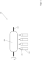
- Figure 1 shows a device 100 for producing a titanium-doped SiO2 soot body 200.
- a plurality of flame hydrolysis burners 220 arranged in a row are arranged along a carrier tube 210 made of aluminum oxide.
- a silicon dioxide raw material and a titanium dioxide raw material are fed to the reaction zone of the flame hydrolysis burner 220 in gaseous form and are decomposed by oxidation and/or hydrolysis and/or pyrolysis.
- SiO2 particles and TiO2 particles are formed, both of which are deposited in layers on the carrier tube 210 to form the SiO2-TiO2 soot body 200.
- the SiO2-TiO2 particles themselves are in the form of agglomerates or aggregates of SiO2 primary particles with particle sizes in the nanometer range.
- the layered structure allows the soot body 200 to have a microscopic layer structure.
- the flame hydrolysis burners 220 can be mounted on a common burner block which is moved back and forth parallel to a longitudinal axis of the carrier tube 210 between two turning points which are fixed in relation to the longitudinal axis.
- This movement of the flame hydrolysis burners 220, mechanical inaccuracies in the feed lines of the raw materials or the burners 220 or even variations in the process temperatures can lead to the soot body 200 having a macroscopic, production-related spatial fluctuation in the physical properties, such as the TiO2 content.
- vitrification of the soot body 200 is shown.
- the vitrification preferably takes place in a process chamber.
- the vitrification temperature is preferably in a range of 1200 to 1500 °C, preferably 1250 to 1350 °C.
- the pressure inside the process chamber is lower than outside the process chamber during vitrification, ie the vitrification is carried out at reduced pressure.
- the vitrification preferably takes place at a pressure of less than 1 mbar.
- the soot body 200 can be moved through a vitrification furnace 250 according to movement arrow 251.
- the mass specified for titanium from 3 wt.% up to 10 wt.% refers to the amount of TiO2 (titanium dioxide), not elemental titanium.
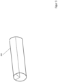
- the cylinder-like glass body 300 is shown.
- a dotted line indicates a section that is cut out of the glass body during the dividing step 1200.
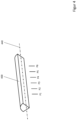
- the rod-like glass body section 400 created in this way is shown in the Figure 4
- the glass body 300 can be divided into a plurality of rod-like glass body sections 400, which have a longitudinal shank 440.
- the glass body sections 400 can have a cross-section similar to a circular sector.
- the microscopic, production-related layer structure is reduced to such an extent that the glass body section 400 is essentially free of layer structure.
- the two homogenization treatments 1600, 2000 do not enable the substrate precursor 900 to be free of long-wave titanium gradients, which significantly influence the quality and usability of the substrate precursor 900 in EUV lithography.
- the glass body section 400 is shown, on which a titanium profile 410 is spatially measured.
- the titanium dioxide content is measured at several measuring points (P1, P2, P3, P4, P5, P6) along the longitudinal axis 420. These measuring points are at a distance of less than 5 cm, in particular less than 2 cm from each other.
- This selective measurement of the titanium dioxide content gives a clear picture of the conditions in the vitreous body section 400. Any fluctuations in the titanium distribution take place on length scales of 0.15 m to 0.75 m.
- the property curve 510 can be measured parallel and analogous to the titanium curve 410.
- the physical property is measured at several measuring points (P1, P2, P3, P4, P5, P6) along the longitudinal axis 420.
- the measuring points are less than 5 cm apart, in particular less than 2 cm apart.
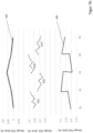
- FIG. 5 The result of a measurement 1300 of a titanium profile 410 and a property profile 510 in the glass body section 400 is shown schematically.
- the amount in wt.% of titanium dioxide or in ppm of the property is plotted as a function of the position along the longitudinal axis 440 of the glass body section 400.
- Figure 4 and 5 only measurement results for six measuring points (P1, P2, P3, P4, P5, P6) are shown.
- the steps and/or aspects of the spatial measurement 1300 of the titanium profile 410 described below also apply to a spatial measurement of at least one property profile 510.
- the titanium dioxide content lies within the specified interval of 3 wt.% to 10 wt.%. However, due to manufacturing reasons, this titanium dioxide content fluctuates along the longitudinal axis 420 of the glass body section 400 between 5.4 wt.% to 6.1 wt.%.
- the amount of a property measured at the six measuring points (P1, P2, P3, P4) here for example the OH content in ppm, as property curve 510. Due to manufacturing reasons, this OH content fluctuates along the longitudinal axis 420 of the glass body section 400 between 150 ppm and 175 ppm.
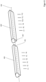
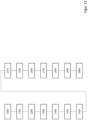
- connection 1500 of a plurality - here two - rod-like glass body sections 400,400' to form an elongated first glass component 600 is shown.
- a flat contact surface 401 of the first glass body section 400 and a flat contact surface 401' of the second glass body section 400' can be joined together by wringing and welded together. This is a "cold joining process" in which at most the immediate area of the contact surface experiences significant heating.
- the joining 1500 can include a joining step in which both glass body sections 400, 400' are softened in an oven and joined together. This is a "hot joining process" in which the individual glass body sections 400, 400' are joined together by welding.
- the titanium dioxide and/or property curves are measured at several measuring points.
- the titanium curve 410 is measured at the measuring points P1, P2, P3, P4, P5, P6.
- the titanium curve 410' is measured at the measuring points P7, P8, P9, P10, P11, P12.
- At least three, in particular at least five, in particular at least eight glass body sections can be connected to one another to form a first glass component 600, which also Figure 9 clarified.
- the titanium profile 410 fluctuates along the longitudinal axis of the glass body section 400.
- the titanium profile also fluctuates between different glass body sections 400, 400'.
- these macroscopic, production-related fluctuations of the individual titanium profiles between different glass body sections 400, 400' were not further taken into account. Rather, only a few, in particular only two glass body sections 400, 400' were previously required for substrate precursors 900 with a low mass, so that the fluctuations occurring between the long-wave titanium profiles 410 in the glass body sections 400, 400' are ignored. This is no longer possible when producing substrate precursors with a mass of more than 50 kg, in particular more than 100 kg, especially if at least four glass body sections have to be connected to one another.
- the Figure 7a , 7b and the Figure 8 illustrate the steps used in the Measure step 1300, which serve to overcome the disadvantages mentioned above.
- a titanium distribution 430 is calculated with the aid of the model and compared with the desired titanium distribution 420.
- steps and/or aspects of minimizing a difference between titanium partitioning and titanium distribution described below also apply to minimizing a second difference between at least one property partitioning and at least one property distribution.
- the starting point is a predetermination 1400 of a desired titanium distribution 420 in the substrate precursor.
- the titanium distribution 420 represents the two-dimensional distribution of the amount of TiO2 in the substrate precursor, in particular along a center line, in particular on the outer surface to be mirrored later, through the substrate precursor.
- the model can calculate a two-dimensional titanium distribution in the substrate precursor from the two-dimensionally determined titanium profiles and their arrangement relative to one another.
- FIG 7a A substrate precursor 900 is shown. This should optimally have a titanium distribution 420, as shown in the upper diagram in Figure 7b As an example, a parabolic titanium distribution 420 within an interval of 4.75 wt.% to 5.5 wt.% TiO2 is desired, which has a maximum in a center of the substrate precursor.
- the desired two-dimensional titanium distribution 420 can be found in the substrate precursor 900 on the outer surface 910 to be mirrored later along a center line 920.
- the type and design of the titanium distribution 420 can depend in particular on the type of use and the conditions of use of the later EUV mirror.
- the titanium distribution - and thus the CTE - can be adapted to the distribution of the incident EUV radiation.
- the model calculates the titanium partitioning 430 in the substrate precursor 900.
- This titanium partitioning 430 is shown in the lower diagram in Figure 7b shown.
- the illustrated course of the calculated titanium distribution 430 does not correspond to a simple linear sequence of the illustrated courses of the titanium courses 410, 410', 410", 410′′′ in the assumed arrangement. Rather, the method steps of the method disclosed here lead to the spatial position and location of a titanium course 410, 410', 410", 410′′′ after running through the method no longer corresponding to the spatial position that the glass body section 400, 400', 400", 400′′′ corresponding to the titanium course had in the first glass body 300.
- the spatial location of the titanium course 410, 410', 410", 410′′′ changes in such a way that a model is required to determine the position and amount of TiO2 in the titanium distribution 430 of the substrate precursor. 900 to calculate.
- the in Figure 7b The calculated titanium distribution 430 shown has a zigzag shape and thus deviates greatly from the desired parabolic titanium distribution 420.
- the model calculates a titanium distribution 430 ⁇ in the substrate precursor 900 from the titanium distributions 410", 410′′′, 410 ⁇ , 410.
- This titanium distribution 430' is more similar in both magnitude and course to the desired titanium distribution 420 than that in Figure 7b shown titanium distribution 430.
- the model calculates the corresponding titanium distribution 430, 430' from each possible arrangement of the vitreous body sections 400, 400', 400", 400′′′ and compares this with the desired titanium distribution 420. For this purpose, all possible arrangements of the vitreous body sections 400, 400', 400", 400′′′ are permuted. Based on this information the model forms a difference between titanium distribution and titanium distribution 420.
- the optimal arrangement is the arrangement in which the amount of the difference, in particular the maximum amount of difference between two spatially equal points on the substrate precursor, is minimal.
- the glass body sections 400, 400', 400", 400′′′ are then positioned and connected according to the optimal arrangement.
- both the aspects concerning the element titanium dioxide and the at least one other property are taken into account when calculating the optimal arrangement of the vitreous body sections.
- a first homogenization treatment 1600 of the first glass component 600 is shown, which is made from the glass body sections 400", 400′′′, 400', 400. Both the glass body and the first glass component 600 made from the glass body sections 400", 400′′′, 400', 400 have microscopic, manufacturing-related layer structures. In order to To reduce this and/or to enable the production of a substantially layer structure-free substrate precursor 900, two homogenization treatments are carried out sequentially.
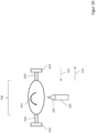
- the first glass component 600 is clamped into a glass lathe 605 equipped with one or more burners 220 and homogenized by means of a forming process, as in the EP 673 888 A1 for the purpose of complete removal of layer structures.
- the glass lathe 605 has two chucks 610, 610', which can be set in rotation 650, 650 ⁇ independently of one another.
- the first glass component 600 is clamped between the two chucks 610, 610 ⁇ .
- Two holding elements 620, 620' can ensure a better fit between the chucks 610, 610' and the first glass component 600.
- the first glass component 600 is heated at certain points using the burner 220 and softened in the process, so that a shear zone 630 is created.
- This shear zone 630 allows an external force, such as a torsional force, tensile force or compressive force, to be applied to the rod-shaped first glass component 600.
- the two chucks 610, 610 ⁇ can rotate in opposite directions 650, 650 ⁇ .
- microscopic, production-related layer structures are effectively reduced in a plane of the shear zone of the first glass component 600.
- the reduction of microscopic, production-related layer structures perpendicular to the plane of the shear zone of the first glass component 600 is significantly lower.
- the Figure 10 illustrates a pushing together 1700 of the first glass component 600 in order to create a spherical glass system 700.
- the first glass component 600 is heated and compressed using the burner 220.
- the pushing together 1700 can be carried out by moving the two chucks 610,610' towards each other, which is illustrated by the movement arrow 612.
- the glass system 700 is then turned 1800 by more than 70 degrees.
- the glass system 700 is removed from the chucks 610,610' and rotated, which the movement arrow 615 is intended to illustrate.
- This rotation ensures that in the second homogenization treatment 2000 that portion of the layer structure which was only slightly or not at all equalized in the first homogenization treatment 1600 can be effectively reduced.
- the glass system 700 After turning 1800 the glass system 700 by more than 70 degrees, it is clamped again in the chucks 610,610'. The glass system 700 is then pulled apart 1900.
- This mechanical deformation of the spherical glass system 700 into an elongated second glass component 800 takes place by heating the glass system 700 with the burner 220 and moving the chucks 610,610' away from each other, which is illustrated by the movement arrow 613.
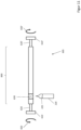
- a second homogenization treatment 2000 of the second glass component 800 is shown.
- the second homogenization treatment 2000 is essentially analogous to the first homogenization treatment 1600.
- the crucial difference is that due to the turning 1800, the layer structure that was previously essentially perpendicular to the longitudinal axis of the glass lathe 605 now lies in the direction of the longitudinal axis of the glass lathe 605.
- the second glass component 800 is clamped between the two chucks 610, 610 ⁇ of the glass lathe 605.
- the second glass component 800 is heated at certain points by means of the burner 220 and softened in the process, so that a second shear zone 640 is created.
- This second shear zone 640 allows an external force, such as a torsional force, tensile or compressive force, to be applied to the rod-shaped second glass component 800.
- an external force such as a torsional force, tensile or compressive force
- Within the second shear zone 640 areas are created that have different tensions or experience different movements, which is accompanied by a shearing effect or stretching and compressing effect.
- the two chucks 610, 610 ⁇ can rotate in opposite directions 650, 650 ⁇ .
- this second homogenization treatment 2000 microscopic, production-related layer structures are effectively reduced in the direction perpendicular to the longitudinal axis of the first glass component 600 and/or in the direction of a longitudinal axis of the second glass component 800.
- a substrate precursor 900 is created which is essentially free of layer structures.
Landscapes
- Chemical & Material Sciences (AREA)
- Engineering & Computer Science (AREA)
- Organic Chemistry (AREA)
- Materials Engineering (AREA)
- Chemical Kinetics & Catalysis (AREA)
- Life Sciences & Earth Sciences (AREA)
- General Chemical & Material Sciences (AREA)
- Geochemistry & Mineralogy (AREA)
- Thermal Sciences (AREA)
- Manufacturing & Machinery (AREA)
- Physics & Mathematics (AREA)
- Ceramic Engineering (AREA)
- Dispersion Chemistry (AREA)
- Glass Compositions (AREA)
- Surface Treatment Of Glass (AREA)
- Preparing Plates And Mask In Photomechanical Process (AREA)
- Glass Melting And Manufacturing (AREA)
- Manufacture, Treatment Of Glass Fibers (AREA)
Claims (12)
- Procédé destiné à fabriquer un précurseur de substrat (900) comportant une masse supérieure à 50 kg, présentant un verre mixte TiO2-SiO2, comprenant les étapes consistant à :• introduire (1000) un matériau brut de dioxyde de silicium et un matériau brut de dioxyde de titane dans une flamme (225),• fabriquer (1100) un corps en verre (300) comportant une teneur en dioxyde de titane allant de 3 % en poids à 10 % en poids, le corps en verre (300) présentant :• un gradient de titane (410, 410`, 410", 410‴) macroscopique dû à la fabrication, et• une structure en couches microscopique due à la fabrication,• répartir (1200) le corps en verre en une pluralité de sections de corps en verre (400, 400`, 400", 400‴) en forme de tige,• mesurer (1300) spatialement le gradient de titane (410, 410`, 410", 410‴) dans chacune des sections de corps en verre (400, 400`, 400", 400‴),• relier (1500) les sections de corps en verre (400, 400`, 400", 400‴) pour la formation d'un premier composant en verre (600) allongé,• effectuer un premier traitement d'homogénéisation (1600) du premier composant en verre (600),• rapprocher (1700) le premier composant en verre (600) afin de créer un système en verre (700) sphérique,• faire tourner (1800) le système en verre (700) de plus de 70 degrés,• écarter (1900) le système en verre (700) pour la formation d'un second composant en verre (800) allongé,• effectuer un second traitement d'homogénéisation (2000) du second composant en verre (800) afin de créer un précurseur de substrat (900), le précurseur de substrat (900) étant sensiblement exempt de structure en couches,caractérisé en ce que
l'étape de mesure comprend les étapes suivantes :• prédétermination (1400) d'une distribution de titane (420) spatiale souhaitable dans le précurseur de substrat (900),• fourniture (1420) d'un modèle d'une répartition de titane (430) dans le précurseur de substrat (900), le modèle dépendant• d'une disposition de la pluralité de sections de corps en verre (400, 400`, 400", 400‴) dans le premier composant en verre (600) les unes par rapport aux autres,• du gradient de titane (410, 410`, 410", 410‴) spatial dans chacune des sections de corps en verre (400, 400`, 400", 400‴), et• des effets de l'étape de rapprochement (1700) et de l'étape de rotation (1800) sur les gradients de titane (410, 410', 410", 410‴) spatiaux dans les sections de corps en verre,• calcul (1450) d'une disposition optimale des sections de corps en verre (400, 400`, 400", 400‴) les unes par rapport aux autres au moyen du modèle, de sorte qu'une différence entre la répartition de titane (430) et la distribution de titane (420) est minimale,• positionnement (1470) des sections de corps en verre (400, 400`, 400", 400‴) de sorte que, dans l'étape de liaison (1500), les sections de corps en verre (400, 400', 400", 400‴) sont reliées selon la disposition optimale calculée. - Procédé selon la revendication 1, caractérisé en ce que le précurseur de substrat (900) présente une masse supérieure à 100 kg, en particulier supérieure à 200 kg, en particulier supérieure à 300 kg.
- Procédé selon l'une des revendications 1 ou 2, caractérisé en ce que le procédé comprend l'étape suivante :• fabrication d'un second corps en verre comportant une teneur en dioxyde de titane allant de 3 % en poids à 10 % en poids, le second corps en verre présentant :• un second gradient de titane macroscopique dû à la fabrication, et• une seconde structure en couches microscopique due à la fabrication,• répartition du second corps en verre en une pluralité de sections de corps en verre en forme de tige.
- Procédé selon au moins l'une des revendications précédentes, caractérisé en ce que, pour la formation du premier composant en verre, au moins trois, en particulier au moins cinq, en particulier au moins huit sections de corps en verre sont reliées.
- Procédé selon au moins l'une des revendications précédentes, caractérisé en ce que la différence entre la répartition de titane (430) et la distribution de titane (420) est inférieure à 1,5 % par rapport à une valeur maximale de la distribution de titane (420), en particulier inférieure à 1,0 %, en particulier inférieure à 0,5 %.
- Procédé selon au moins l'une des revendications 1 à 5, caractérisé en ce que le corps en verre présente au moins l'un des gradients de propriétés (510) suivants :• un gradient d'OH macroscopique dû à la fabrication,• un gradient de CTE macroscopique dû à la fabrication,• un gradient de fluor macroscopique dû à la fabrication,• un gradient de bulles macroscopique dû à la fabrication,• un gradient d'ODC macroscopique dû à la fabrication,• un gradient de Ti3+ macroscopique dû à la fabrication,• un gradient d'impuretés métalliques macroscopique dû à la fabrication.
- Procédé selon la revendication 6, caractérisé en ce que, dans l'étape de mesure, au moins l'un des gradients de propriétés (510) est mesuré dans chacune des sections de corps en verre (400, 400', 400", 400‴).
- Procédé selon la revendication 7, caractérisé en ce que l'étape de mesure comprend les étapes suivantes :• prédétermination d'une distribution de propriétés spatiale souhaitable dans le précurseur de substrat (900),• fourniture d'un modèle d'une répartition de propriétés dans le précurseur de substrat (900), le modèle dépendant• d'une disposition de la pluralité de sections de corps en verre dans le premier composant en verre les unes par rapport aux autres,• d'un gradient de propriétés (510) spatial dans chacune des sections de corps en verre, et• des effets de l'étape de rapprochement et de l'étape de rotation sur le gradient de propriétés spatial dans les sections de corps en verre,• calcul, au moyen du modèle, d'une disposition optimale des sections de corps en verre (400, 400', 400", 400‴) les unes par rapport aux autres, de sorte qu'une somme de différences est minimale, la somme de différences présentant• la différence entre la répartition de titane (430) et la distribution de titane (420) ; et• la seconde différence entre la répartition des propriétés et la distribution des propriétés,• positionnement des sections de corps en verre (400, 400', 400", 400‴) de sorte que, à l'étape de liaison (1500), les sections de corps en verre (400, 400', 400", 400‴) sont reliées selon la disposition optimale calculée.
- Procédé selon la revendication 8, caractérisé en ce que la somme de différences est inférieure à 1,5 % par rapport à une somme d'une valeur maximale de la distribution de titane (420) et d'une valeur maximale de la distribution de propriétés, en particulier inférieure à 1,0 %, en particulier inférieure à 0,5 %.
- Procédé selon au moins l'une des revendications précédentes, caractérisé en ce que l'étape de fabrication (1100) du corps en verre comprend au moins les étapes suivantes :• création d'un corps en suie (200) poreux, le gradient de titane macroscopique dû à la fabrication s'étendant sensiblement le long d'un axe longitudinal et la structure en couches microscopique due au processus s'étendant sensiblement le long d'un axe de croissance,• vitrification du corps en suie afin de créer le corps en verre cylindrique.
- Procédé selon au moins l'une des revendications précédentes, caractérisé en ce que le premier composant en verre (600) est chauffé avant l'étape de rapprochement (1700).
- Procédé selon au moins l'une des revendications précédentes, caractérisé en ce que la liaison (1500) est effectuée au niveau d'une surface de contact (401) respective des sections de corps en verre (400, 400', 400", 400‴).
Priority Applications (4)
| Application Number | Priority Date | Filing Date | Title |
|---|---|---|---|
| EP22186404.4A EP4310060B1 (fr) | 2022-07-22 | 2022-07-22 | Procédé d'optimisation de la distribution d'oxyde de titane dans des précurseurs de substrats de tio2-sio2 solides |
| CN202310830196.6A CN117430336B (zh) | 2022-07-22 | 2023-07-07 | 用于优化固体衬底前体中的特性曲线的方法 |
| JP2023114095A JP7577798B2 (ja) | 2022-07-22 | 2023-07-11 | 固体基板前駆体の特性プロファイルを最適化する方法 |
| US18/352,741 US20240025794A1 (en) | 2022-07-22 | 2023-07-14 | Method for optimizing property profiles in solid substrate precursors |
Applications Claiming Priority (1)
| Application Number | Priority Date | Filing Date | Title |
|---|---|---|---|
| EP22186404.4A EP4310060B1 (fr) | 2022-07-22 | 2022-07-22 | Procédé d'optimisation de la distribution d'oxyde de titane dans des précurseurs de substrats de tio2-sio2 solides |
Publications (2)
| Publication Number | Publication Date |
|---|---|
| EP4310060A1 EP4310060A1 (fr) | 2024-01-24 |
| EP4310060B1 true EP4310060B1 (fr) | 2024-10-30 |
Family
ID=82701650
Family Applications (1)
| Application Number | Title | Priority Date | Filing Date |
|---|---|---|---|
| EP22186404.4A Active EP4310060B1 (fr) | 2022-07-22 | 2022-07-22 | Procédé d'optimisation de la distribution d'oxyde de titane dans des précurseurs de substrats de tio2-sio2 solides |
Country Status (4)
| Country | Link |
|---|---|
| US (1) | US20240025794A1 (fr) |
| EP (1) | EP4310060B1 (fr) |
| JP (1) | JP7577798B2 (fr) |
| CN (1) | CN117430336B (fr) |
Family Cites Families (16)
| Publication number | Priority date | Publication date | Assignee | Title |
|---|---|---|---|---|
| US5262896A (en) * | 1992-01-29 | 1993-11-16 | Lightpath Technologies, L.P. | Refractive elements with graded properties and methods of making same |
| JP3194667B2 (ja) | 1994-03-26 | 2001-07-30 | 信越石英株式会社 | 光学用合成石英ガラス成形体及びその製造方法 |
| JP4933777B2 (ja) * | 2004-12-28 | 2012-05-16 | 信越石英株式会社 | 脈理のないシリカ・チタニアガラスの製造方法 |
| JP4568219B2 (ja) | 2005-02-01 | 2010-10-27 | 信越石英株式会社 | 均質なシリカ・チタニアガラスの製造方法 |
| JP4506689B2 (ja) * | 2005-06-14 | 2010-07-21 | 旭硝子株式会社 | 予備研磨されたガラス基板表面を仕上げ加工する方法 |
| KR101494477B1 (ko) * | 2007-05-09 | 2015-02-17 | 코닝 인코포레이티드 | 낮은 oh 및 od 수준을 갖는 유리 |
| KR101740067B1 (ko) * | 2009-01-13 | 2017-05-25 | 아사히 가라스 가부시키가이샤 | TiO₂를 함유하는 실리카 유리를 포함하는 광학 부재 |
| JP5287271B2 (ja) * | 2009-01-13 | 2013-09-11 | 旭硝子株式会社 | TiO2を含有するシリカガラスの成型方法およびそれによって成型されたEUVリソグラフィ用光学部材 |
| DE102009043680A1 (de) * | 2009-09-30 | 2011-03-31 | Heraeus Quarzglas Gmbh & Co. Kg | Rohling aus Titan-dotiertem, hochkieselsäurehaltigem Glas für ein Spiegelsubstrat für den Einsatz in der EUV-Lithographie und Verfahren für seine Herstellung |
| JPWO2012105513A1 (ja) * | 2011-01-31 | 2014-07-03 | 旭硝子株式会社 | チタニアを含有するシリカガラス体の製造方法およびチタニアを含有するシリカガラス体 |
| JP5768452B2 (ja) * | 2011-04-11 | 2015-08-26 | 信越化学工業株式会社 | チアニアドープ石英ガラスの製造方法 |
| JPWO2013084978A1 (ja) * | 2011-12-09 | 2015-04-27 | 信越石英株式会社 | チタニア−シリカガラス製euvリソグラフィ用フォトマスク基板 |
| JP6241276B2 (ja) * | 2013-01-22 | 2017-12-06 | 信越化学工業株式会社 | Euvリソグラフィ用部材の製造方法 |
| DE102013101328B3 (de) * | 2013-02-11 | 2014-02-13 | Heraeus Quarzglas Gmbh & Co. Kg | Rohling aus TiO2-SiO2-Glas für ein Spiegelsubstrat für den Einsatz in der EUV-Lithographie sowie Verfahren für dessen Herstellung |
| US9382151B2 (en) * | 2014-01-31 | 2016-07-05 | Corning Incorporated | Low expansion silica-titania articles with a Tzc gradient by compositional variation |
| EP2960219B1 (fr) | 2014-06-27 | 2019-01-16 | Heraeus Quarzglas GmbH & Co. KG | Ebauche en verre de quartz doté de titane pour un substrat de miroir à utiliser dans la lithographie EUV et son procédé de fabrication |
-
2022
- 2022-07-22 EP EP22186404.4A patent/EP4310060B1/fr active Active
-
2023
- 2023-07-07 CN CN202310830196.6A patent/CN117430336B/zh active Active
- 2023-07-11 JP JP2023114095A patent/JP7577798B2/ja active Active
- 2023-07-14 US US18/352,741 patent/US20240025794A1/en active Pending
Also Published As
| Publication number | Publication date |
|---|---|
| CN117430336B (zh) | 2026-05-12 |
| JP7577798B2 (ja) | 2024-11-05 |
| EP4310060A1 (fr) | 2024-01-24 |
| JP2024014777A (ja) | 2024-02-01 |
| US20240025794A1 (en) | 2024-01-25 |
| CN117430336A (zh) | 2024-01-23 |
Similar Documents
| Publication | Publication Date | Title |
|---|---|---|
| DE69516571T2 (de) | Formteil aus synthetischem Quarzglas für optische Zweck und Verfahren zu dessen Herstellung | |
| EP1747175B1 (fr) | Ebauche de verre de quartz et son procede de production | |
| DE112005003308B4 (de) | Quarzglas mit hoher Brechungsindex-Homogenität und Verfahren zur Herstellung desselben | |
| EP3766850B1 (fr) | Procédé de fabrication d'une fibre à coeur creux et de fabrication d'une préforme pour fibre à coeur creux | |
| EP4030203A1 (fr) | Préformé antirésonance à deux points de contact | |
| WO2021009227A1 (fr) | Procédé pour préparer une fibre à âme creuse et pour préparer une préforme d'une fibre à âme creuse | |
| DE102013101328B3 (de) | Rohling aus TiO2-SiO2-Glas für ein Spiegelsubstrat für den Einsatz in der EUV-Lithographie sowie Verfahren für dessen Herstellung | |
| EP3766851B1 (fr) | Procédé de fabrication d'une fibre à coeur creux et de fabrication d'une préforme de fibre à coeur creux | |
| EP4011840A1 (fr) | Méthode de fabircation d'une préforme de fibre à coeur creux anti résonante | |
| EP3766844A1 (fr) | Procédé de fabrication d'une fibre à coeur creux et d'une préforme de fibre à coeur creux | |
| EP0187405A2 (fr) | Procédé pour la fabrication de fibres optiques | |
| EP1321440B1 (fr) | Procédé de fabrication d'un produit en vitrocéramique | |
| EP4308511A1 (fr) | Composants de précision ayant un comportement de dilatation thermique spécifique | |
| EP2960219B1 (fr) | Ebauche en verre de quartz doté de titane pour un substrat de miroir à utiliser dans la lithographie EUV et son procédé de fabrication | |
| DE60010054T2 (de) | Verfahren zum Herstellen einer optischen Faser mit Einstellung des Kerndiameterprofils der Vorform | |
| DE69815324T2 (de) | Verfahren zur herstellung von hochreinem quarzglas durch ein sol-gelverfahren | |
| EP3643688B1 (fr) | Procédé d'homogénéisation de verre | |
| WO2015043957A1 (fr) | Poli-miroir pour lithographie euv sans expansion due au rayonnement euv | |
| DE102013002802B4 (de) | Verfahren zur Herstellung von Titandioxid-enthaltendem Quarzglas-Körper | |
| EP4310060A1 (fr) | Procédé d'optimisation de la distribution d'oxyde de titane dans des précurseurs de substrats de tio2-sio2 solides | |
| DE102005043289B3 (de) | Verfahren zur Herstellung eines Halbzeugs für ein optisches Bauteil hoher Homogenität, zur Durchführung des Verfahrens geeigneter Rohling sowie Verwendung des Rohlings und des Halbzeugs | |
| EP0209945B1 (fr) | Procédé de fabrication de fibres optiques | |
| EP2454205B1 (fr) | Procédé de fabrication d'une lentille ménisque en verre de silice synthétique | |
| EP1288169A1 (fr) | Méthode de dopage avec hydrogène d'objets en verre de silice pour améliorer l'homogénéité de l'indice de réfraction et la résistance à laser avec maintien d'une biréfringence par compression déterminé préalablement, et des corps en verre de silice ainsi produits | |
| DE102011110247B4 (de) | Verfahren zur Herstellung eines Halbzeugs zur Fertigung einer biegeoptimierten Lichtleitfaser |
Legal Events
| Date | Code | Title | Description |
|---|---|---|---|
| PUAI | Public reference made under article 153(3) epc to a published international application that has entered the european phase |
Free format text: ORIGINAL CODE: 0009012 |
|
| STAA | Information on the status of an ep patent application or granted ep patent |
Free format text: STATUS: THE APPLICATION HAS BEEN PUBLISHED |
|
| AK | Designated contracting states |
Kind code of ref document: A1 Designated state(s): AL AT BE BG CH CY CZ DE DK EE ES FI FR GB GR HR HU IE IS IT LI LT LU LV MC MK MT NL NO PL PT RO RS SE SI SK SM TR |
|
| STAA | Information on the status of an ep patent application or granted ep patent |
Free format text: STATUS: REQUEST FOR EXAMINATION WAS MADE |
|
| 17P | Request for examination filed |
Effective date: 20240304 |
|
| GRAP | Despatch of communication of intention to grant a patent |
Free format text: ORIGINAL CODE: EPIDOSNIGR1 |
|
| STAA | Information on the status of an ep patent application or granted ep patent |
Free format text: STATUS: GRANT OF PATENT IS INTENDED |
|
| RIC1 | Information provided on ipc code assigned before grant |
Ipc: C03B 32/00 20060101ALI20240625BHEP Ipc: C03B 23/049 20060101ALI20240625BHEP Ipc: C03B 23/047 20060101ALI20240625BHEP Ipc: C03B 19/14 20060101AFI20240625BHEP |
|
| INTG | Intention to grant announced |
Effective date: 20240715 |
|
| RIN1 | Information on inventor provided before grant (corrected) |
Inventor name: BECKER, KLAUS |
|
| GRAS | Grant fee paid |
Free format text: ORIGINAL CODE: EPIDOSNIGR3 |
|
| GRAA | (expected) grant |
Free format text: ORIGINAL CODE: 0009210 |
|
| STAA | Information on the status of an ep patent application or granted ep patent |
Free format text: STATUS: THE PATENT HAS BEEN GRANTED |
|
| AK | Designated contracting states |
Kind code of ref document: B1 Designated state(s): AL AT BE BG CH CY CZ DE DK EE ES FI FR GB GR HR HU IE IS IT LI LT LU LV MC MK MT NL NO PL PT RO RS SE SI SK SM TR |
|
| REG | Reference to a national code |
Ref country code: GB Ref legal event code: FG4D Free format text: NOT ENGLISH |
|
| REG | Reference to a national code |
Ref country code: CH Ref legal event code: EP |
|
| REG | Reference to a national code |
Ref country code: IE Ref legal event code: FG4D Free format text: LANGUAGE OF EP DOCUMENT: GERMAN |
|
| REG | Reference to a national code |
Ref country code: DE Ref legal event code: R096 Ref document number: 502022002007 Country of ref document: DE |
|
| REG | Reference to a national code |
Ref country code: NL Ref legal event code: FP |
|
| REG | Reference to a national code |
Ref country code: LT Ref legal event code: MG9D |
|
| PG25 | Lapsed in a contracting state [announced via postgrant information from national office to epo] |
Ref country code: IS Free format text: LAPSE BECAUSE OF FAILURE TO SUBMIT A TRANSLATION OF THE DESCRIPTION OR TO PAY THE FEE WITHIN THE PRESCRIBED TIME-LIMIT Effective date: 20250228 Ref country code: PT Free format text: LAPSE BECAUSE OF FAILURE TO SUBMIT A TRANSLATION OF THE DESCRIPTION OR TO PAY THE FEE WITHIN THE PRESCRIBED TIME-LIMIT Effective date: 20250228 Ref country code: HR Free format text: LAPSE BECAUSE OF FAILURE TO SUBMIT A TRANSLATION OF THE DESCRIPTION OR TO PAY THE FEE WITHIN THE PRESCRIBED TIME-LIMIT Effective date: 20241030 |
|
| PG25 | Lapsed in a contracting state [announced via postgrant information from national office to epo] |
Ref country code: FI Free format text: LAPSE BECAUSE OF FAILURE TO SUBMIT A TRANSLATION OF THE DESCRIPTION OR TO PAY THE FEE WITHIN THE PRESCRIBED TIME-LIMIT Effective date: 20241030 |
|
| PG25 | Lapsed in a contracting state [announced via postgrant information from national office to epo] |
Ref country code: BG Free format text: LAPSE BECAUSE OF FAILURE TO SUBMIT A TRANSLATION OF THE DESCRIPTION OR TO PAY THE FEE WITHIN THE PRESCRIBED TIME-LIMIT Effective date: 20241030 |
|
| PG25 | Lapsed in a contracting state [announced via postgrant information from national office to epo] |
Ref country code: ES Free format text: LAPSE BECAUSE OF FAILURE TO SUBMIT A TRANSLATION OF THE DESCRIPTION OR TO PAY THE FEE WITHIN THE PRESCRIBED TIME-LIMIT Effective date: 20241030 |
|
| PG25 | Lapsed in a contracting state [announced via postgrant information from national office to epo] |
Ref country code: NO Free format text: LAPSE BECAUSE OF FAILURE TO SUBMIT A TRANSLATION OF THE DESCRIPTION OR TO PAY THE FEE WITHIN THE PRESCRIBED TIME-LIMIT Effective date: 20250130 |
|
| PG25 | Lapsed in a contracting state [announced via postgrant information from national office to epo] |
Ref country code: LV Free format text: LAPSE BECAUSE OF FAILURE TO SUBMIT A TRANSLATION OF THE DESCRIPTION OR TO PAY THE FEE WITHIN THE PRESCRIBED TIME-LIMIT Effective date: 20241030 Ref country code: GR Free format text: LAPSE BECAUSE OF FAILURE TO SUBMIT A TRANSLATION OF THE DESCRIPTION OR TO PAY THE FEE WITHIN THE PRESCRIBED TIME-LIMIT Effective date: 20250131 |
|
| PG25 | Lapsed in a contracting state [announced via postgrant information from national office to epo] |
Ref country code: PL Free format text: LAPSE BECAUSE OF FAILURE TO SUBMIT A TRANSLATION OF THE DESCRIPTION OR TO PAY THE FEE WITHIN THE PRESCRIBED TIME-LIMIT Effective date: 20241030 |
|
| PG25 | Lapsed in a contracting state [announced via postgrant information from national office to epo] |
Ref country code: RS Free format text: LAPSE BECAUSE OF FAILURE TO SUBMIT A TRANSLATION OF THE DESCRIPTION OR TO PAY THE FEE WITHIN THE PRESCRIBED TIME-LIMIT Effective date: 20250130 |
|
| PG25 | Lapsed in a contracting state [announced via postgrant information from national office to epo] |
Ref country code: SM Free format text: LAPSE BECAUSE OF FAILURE TO SUBMIT A TRANSLATION OF THE DESCRIPTION OR TO PAY THE FEE WITHIN THE PRESCRIBED TIME-LIMIT Effective date: 20241030 |
|
| PG25 | Lapsed in a contracting state [announced via postgrant information from national office to epo] |
Ref country code: DK Free format text: LAPSE BECAUSE OF FAILURE TO SUBMIT A TRANSLATION OF THE DESCRIPTION OR TO PAY THE FEE WITHIN THE PRESCRIBED TIME-LIMIT Effective date: 20241030 |
|
| PG25 | Lapsed in a contracting state [announced via postgrant information from national office to epo] |
Ref country code: EE Free format text: LAPSE BECAUSE OF FAILURE TO SUBMIT A TRANSLATION OF THE DESCRIPTION OR TO PAY THE FEE WITHIN THE PRESCRIBED TIME-LIMIT Effective date: 20241030 |
|
| PG25 | Lapsed in a contracting state [announced via postgrant information from national office to epo] |
Ref country code: RO Free format text: LAPSE BECAUSE OF FAILURE TO SUBMIT A TRANSLATION OF THE DESCRIPTION OR TO PAY THE FEE WITHIN THE PRESCRIBED TIME-LIMIT Effective date: 20241030 |
|
| PG25 | Lapsed in a contracting state [announced via postgrant information from national office to epo] |
Ref country code: SK Free format text: LAPSE BECAUSE OF FAILURE TO SUBMIT A TRANSLATION OF THE DESCRIPTION OR TO PAY THE FEE WITHIN THE PRESCRIBED TIME-LIMIT Effective date: 20241030 |
|
| PG25 | Lapsed in a contracting state [announced via postgrant information from national office to epo] |
Ref country code: CZ Free format text: LAPSE BECAUSE OF FAILURE TO SUBMIT A TRANSLATION OF THE DESCRIPTION OR TO PAY THE FEE WITHIN THE PRESCRIBED TIME-LIMIT Effective date: 20241030 |
|
| PG25 | Lapsed in a contracting state [announced via postgrant information from national office to epo] |
Ref country code: IT Free format text: LAPSE BECAUSE OF FAILURE TO SUBMIT A TRANSLATION OF THE DESCRIPTION OR TO PAY THE FEE WITHIN THE PRESCRIBED TIME-LIMIT Effective date: 20241030 |
|
| REG | Reference to a national code |
Ref country code: DE Ref legal event code: R097 Ref document number: 502022002007 Country of ref document: DE |
|
| PGFP | Annual fee paid to national office [announced via postgrant information from national office to epo] |
Ref country code: NL Payment date: 20250721 Year of fee payment: 4 |
|
| PLBE | No opposition filed within time limit |
Free format text: ORIGINAL CODE: 0009261 |
|
| STAA | Information on the status of an ep patent application or granted ep patent |
Free format text: STATUS: NO OPPOSITION FILED WITHIN TIME LIMIT |
|
| PG25 | Lapsed in a contracting state [announced via postgrant information from national office to epo] |
Ref country code: SE Free format text: LAPSE BECAUSE OF FAILURE TO SUBMIT A TRANSLATION OF THE DESCRIPTION OR TO PAY THE FEE WITHIN THE PRESCRIBED TIME-LIMIT Effective date: 20241030 |
|
| 26N | No opposition filed |
Effective date: 20250731 |
|
| PGFP | Annual fee paid to national office [announced via postgrant information from national office to epo] |
Ref country code: DE Payment date: 20250722 Year of fee payment: 4 |
|
| P01 | Opt-out of the competence of the unified patent court (upc) registered |
Free format text: CASE NUMBER: UPC_APP_6420_4310060/2025 Effective date: 20250909 |
|
| PGFP | Annual fee paid to national office [announced via postgrant information from national office to epo] |
Ref country code: AT Payment date: 20251020 Year of fee payment: 4 |
|
| REG | Reference to a national code |
Ref country code: CH Ref legal event code: H13 Free format text: ST27 STATUS EVENT CODE: U-0-0-H10-H13 (AS PROVIDED BY THE NATIONAL OFFICE) Effective date: 20260224 |
|
| PG25 | Lapsed in a contracting state [announced via postgrant information from national office to epo] |
Ref country code: LU Free format text: LAPSE BECAUSE OF NON-PAYMENT OF DUE FEES Effective date: 20250722 |
|
| REG | Reference to a national code |
Ref country code: BE Ref legal event code: MM Effective date: 20250731 |
|
| PG25 | Lapsed in a contracting state [announced via postgrant information from national office to epo] |
Ref country code: BE Free format text: LAPSE BECAUSE OF NON-PAYMENT OF DUE FEES Effective date: 20250731 |
|
| PG25 | Lapsed in a contracting state [announced via postgrant information from national office to epo] |
Ref country code: FR Free format text: LAPSE BECAUSE OF NON-PAYMENT OF DUE FEES Effective date: 20250731 |
|
| PG25 | Lapsed in a contracting state [announced via postgrant information from national office to epo] |
Ref country code: CH Free format text: LAPSE BECAUSE OF NON-PAYMENT OF DUE FEES Effective date: 20250731 |
|
| PG25 | Lapsed in a contracting state [announced via postgrant information from national office to epo] |
Ref country code: LT Free format text: LAPSE BECAUSE OF FAILURE TO SUBMIT A TRANSLATION OF THE DESCRIPTION OR TO PAY THE FEE WITHIN THE PRESCRIBED TIME-LIMIT Effective date: 20241030 |
|
| PG25 | Lapsed in a contracting state [announced via postgrant information from national office to epo] |
Ref country code: IE Free format text: LAPSE BECAUSE OF NON-PAYMENT OF DUE FEES Effective date: 20250722 |
|
| PG25 | Lapsed in a contracting state [announced via postgrant information from national office to epo] |
Ref country code: MC Free format text: LAPSE BECAUSE OF FAILURE TO SUBMIT A TRANSLATION OF THE DESCRIPTION OR TO PAY THE FEE WITHIN THE PRESCRIBED TIME-LIMIT Effective date: 20241030 |