EP4310234A1 - Dispositif de sélection et de présentation de fils de trame - Google Patents
Dispositif de sélection et de présentation de fils de trame Download PDFInfo
- Publication number
- EP4310234A1 EP4310234A1 EP22185744.4A EP22185744A EP4310234A1 EP 4310234 A1 EP4310234 A1 EP 4310234A1 EP 22185744 A EP22185744 A EP 22185744A EP 4310234 A1 EP4310234 A1 EP 4310234A1
- Authority
- EP
- European Patent Office
- Prior art keywords
- light source
- weft
- holding plate
- section
- weaving machine
- Prior art date
- Legal status (The legal status is an assumption and is not a legal conclusion. Google has not performed a legal analysis and makes no representation as to the accuracy of the status listed.)
- Granted
Links
Images





Classifications
-
- D—TEXTILES; PAPER
- D03—WEAVING
- D03D—WOVEN FABRICS; METHODS OF WEAVING; LOOMS
- D03D47/00—Looms in which bulk supply of weft does not pass through shed, e.g. shuttleless looms, gripper shuttle looms, dummy shuttle looms
- D03D47/34—Handling the weft between bulk storage and weft-inserting means
- D03D47/38—Weft pattern mechanisms
-
- D—TEXTILES; PAPER
- D03—WEAVING
- D03J—AUXILIARY WEAVING APPARATUS; WEAVERS' TOOLS; SHUTTLES
- D03J1/00—Auxiliary apparatus combined with or associated with looms
- D03J1/24—Mirrors or other arrangements for inspecting loom parts
Definitions
- the invention relates to a device for selecting and presenting weft threads to an insertion element of a weaving machine.
- the invention further relates to an assembly comprising a device for selecting and presenting weft threads to the insertion element and a control unit.
- the invention relates to a weaving machine comprising an insertion element, in particular a gripper, and a device for selecting and presenting weft threads to the insertion element.
- a device for selecting and presenting weft threads to an insertion element of a weaving machine which comprises a weft feeder element, wherein the weft feeder element is mounted so as to be moveable between a rest position and a presenting position, and wherein the device further comprises a light source, which is configured and arranged for illuminating a weft insertion zone from above.
- the indefinite article “a” or “an” means “one or more”.
- the device comprises a number of weft feeder elements, wherein each weft feeder element is mounted so as to be moveable between a rest position and a presenting position.
- the device is equipped with more than one light source.
- the expressions “first” and “second” are only used to distinguish one element from another element and not to indicate any order of the elements.
- the weft insertion zone is defined as a zone comprising a presenting zone and a cutting zone.
- the presenting zone is defined as a zone including an area in which a weft thread guide, for example a needle eye, of the weft feeder element is arranged when the weft feeder element is moved into the presenting position for presenting a weft thread threaded thereto to the insertion element, in particular to a gripper, and including an area in which the weft thread presented by the weft feeder element is taken over by the insertion element, in particular the gripper.
- the cutting zone is defined as a zone in which the weft thread taken over by the insertion element is cut off from the fabric using a weft cutter, also referred to simply as cutter.
- the cutting zone also includes an area, in which a drive for the cutter is arranged. In other embodiments, the drive for the cutter is arranged outside the cutting zone.
- the weft feeder element or each weft feeder element in case of several weft feeder elements, is moved into the presenting position for supplying and/or fitting, in particular threading, a weft thread to the weft feeder element.
- the weft feeder element is arranged between the rest position and the presenting position of the weft feeder element.
- the weft feeder element is arranged between the rest position and the presenting position, but closer to the presenting position, so that the operator can easily reach the weft thread guide.
- the light source in embodiments is also arranged and configured for illuminating a zone referred to as threading zone, i.e., a zone, in which the weft thread guides are arranged for supplying and/or fitting weft threads to the weft thread guides.
- threading zone i.e., a zone
- weft thread guides are arranged for supplying and/or fitting weft threads to the weft thread guides.
- Providing the device for selecting and presenting weft threads to an insertion element with a light source allows to improve the visibility of elements in the weft insertion zone for a visual inspection of a processes, which are crucial for a proper insertion of weft threads and, thus, a weaving process.
- the concept of the invention differs from the prior art in that the light source forms part of the device for selecting and presenting weft threads to an insertion element of a weaving machine. This allows for a machine-mounted light source without the necessity of any additional mounting structure for the light source. Further, when shifting the device for selecting and presenting weft threads to the insertion element in order to adjust a position of the device to a weaving width, the light source is moved with the device and remains in a fixed position relative to the presenting zone. Hence, after adjusting the weaving width, the light source is ready for use without any additional set-up operation.
- a machine-mounted light source is advantageous as it allows operators to use at their own choice either hand or both hands for different tasks.
- the operator is less likely to bring body parts close to moving elements of the weaving machine.
- a machine-mounted light source increases a safety of the weaving machine.
- the light source is mounted to the device via a hinge, wherein the hinge allows the light source to be folded out of the way in times of non-use.
- the hinge allows a fine adjustment of a direction of the light beam emitted by the light source.
- the light source is mounted fixed in position at the device.
- the light source is arranged such arranged such that a centre axis of a beam of light emitted from the light source towards the weft insertion zone is a vertical axis.
- An - at least essentially - vertical light beam allows for a good illumination of the weft insertion zone, without an operator visually inspecting the weft insertion zone being dazzled by the light source.
- the light source is mounted at a fabric-side of the device.
- the device is mounted to a weaving machine such that - seen in an insertion direction - one side is arranged closer to a fabric to be woven than the opposite side.
- the side arranged closer to the fabric to be woven is referred to as fabric-side.
- Mounting the light source at a fabric-side is advantageous for arranging the light source so that no or no large parts of the device and/or of the weaving machine protrude into the beam of light between the light source and the weft insertion zone. In other words, it is avoided that such parts cause a shadow to be cast in the weft insertion zone.
- the device comprises a support arm having a first section extending upwards for mounting the device to the weaving machine, wherein the first section and the light source are arranged at opposite sides of the device.
- the expression first section is used for describing a section having a main extension direction in a vertical direction.
- the first section is inclined with respect to the vertical direction.
- the device comprises a holding plate and the support arm having a first section mounting the holding plate to the weaving machine, wherein the weft feeder element is mounted to the holding plate and the holding plate is mounted to the support arm, and wherein the first section and the light source are arranged at opposite sides of the device.
- the support arm is L-shaped having the first section and a second section extending transverse to the first section, wherein the holding plate is mounted to the second section of the support arm.
- the holding plate is detachably mounted to the support arm. In other embodiments, the holding plate is non-detachably mounted to the support arm.
- the device comprises a number of weft feeder elements that are arranged side by side in an insertion direction on the holding plate, wherein the light source is mounted to the holding plate adjacent to and downstream of a last weft feeder element in the insertion direction.
- the holding plate is inclined with respect to the insertion direction.
- the weft feeder elements are arranged in a staggered arrangement on the holding plate. For avoiding an increase in size of the holding plate, in embodiments of the holding plate, at a fabric-side of the holding plate a protrusion is provided via which the light source is mounted to the holding plate.
- the light source is arranged between the holding plate and the woven fabric and/or between the holding plate and a point at which the weft threads to be inserted are connected to the woven fabric.
- the protrusion forms an integral part of the holding plate. In other embodiments, the protrusion forms an integral part of a housing of the light source. In still another embodiment, the protrusion is an intermediate piece.
- a height of the light source with respect to the weft insertion zone can be set in consideration of a type of light source and a size of the weft insertion zone to be illuminated.
- the light source is arranged between 10 cm and 30 cm above the weft insertion zone.
- the light source is a stroboscopic light source, which is configured to produce flashes of light.
- a stroboscopic light source allows an observation of moving parts of the weaving machine even when weaving with high weaving speeds, wherein in case that a frequency of the stroboscopic light source is selected properly, an element of a weaving machine performing a periodic movement appears frozen in a static state.
- mounting the light source fixed in position provides an intrinsic safety advantage, as an un-experienced operator holding a stroboscopic light source in a hand may come close to moving parts of the weaving machine, which for the operator appear to be not moving or to be moving only with a low speed.
- the light source is selectively operable in a stroboscopic mode, in which it produces flashes of light, or in a continuous mode.
- a stroboscopic mode in which it produces flashes of light
- This allows for example the use of one common light source for an illumination of the weft insertion zone for supplying and/or fitting a weft thread to a weft feeder element in a continuous mode as well as for a visual inspection of moving parts in a stroboscopic mode.
- a flashing frequency of the stroboscopic light source is adapted to a weaving frequency of the weaving machine, wherein the flashing frequency is selectively settable to be the same or an even multiple of the weaving frequency or a non-integer multiple of the weaving frequency.
- a moment or angle in the weaving cycle, in which flashes of light are produced in embodiments is settable and/or preset upon calibration of the weaving machine, wherein the moment or angle can be different for each weft thread presented by one of the number of weft feeder elements.
- a flashing frequency is the same or an even multiple of the weaving frequency, such that a moment or angle in the weaving cycle is kept constant for showing a selected moving part in a frozen position.
- the flashing frequency is a non-integer multiple of the weaving frequency, in particular slightly lower or slightly higher than the weaving frequency, so that it is possible to see the observed moving part moving forward or rearward under the action of the stroboscopic light.
- This stroboscopic light allows a visual inspection of a takeover of a weft thread with the insertion element, wherein it is possible to visually check at which position the weft thread is actually taken over and if the takeover occurs in an intended way.
- the insertion element reliably takes the presented weft thread from the weft feeder element and/or whether the weft feeder element is in the presenting position at a desired instant.
- it is advantageous that the weft feeder element is in the presenting position a defined angle before the presented weft thread is being taken over by the insertion element.
- the results of the visual inspection of a takeover are used for optimizing a process after the weft thread has been taken over by the insertion element, wherein after the takeover, the weft feeder element is moved from the presenting position towards the rest position into an intermediate position for decreasing frictional forces between a weft thread guide of the weft feeder element and the weft thread guided in the weft thread guide.
- a cutting moment i.e., an instant or moment, in which the weft thread is cut off a fabric for an insertion, is inspected.
- the stroboscopic light source comprises a plurality of light emitting diodes (LEDs).
- the light source is an LED lamp.
- LED lamps allow for a setting of the flashing frequency as well as of the duration of the flashing, and in particular allow also a continuous illumination.
- a duration of the flashing in embodiments can also be adapted to the weaving machine speed, for example so that the duration is longer at lower weaving machine speeds.
- the device further comprises a camera, in particular a camera attached to the holding plate.
- the camera takes advantage of the illumination of the weft insertion zone for taken pictures of the weft insertion zone.
- the pictures taken by the camera can be viewed on a display of the weaving machine or on a peripheral device, wherein the pictures can also be viewed in slow motion. This allows for a good analyzation of the processes in the weft insertion zone, in particular during takeover of the weft thread and cutting of the weft thread.
- an assembly comprising a device as described above and a control unit configured for controlling an operation of the light source.
- the control unit in embodiments forms part of a central control unit of the weaving machine.
- an independent control unit is provided, which is communicating with a central control unit of the weaving machine.
- the control unit in an embodiment causes a central control unit to turn off all other light sources on a weaving machine when turning on the light source of the device and/or when operating the light source in a stroboscopic mode.
- the control unit allows an adaptation of a flashing frequency of the light source to a weaving frequency.
- a user interface to the control unit uses a pushbutton, wherein depending on a duration of pushing the pushbutton and/or a pattern applied for pushing the pushbutton, different operation modes of the light source can be selected.
- a communication with the control unit is established via a display of the weaving machine and/or a control panel of the weaving machine.
- a weaving machine comprising an insertion element, in particular a gripper, and the device for selecting and presenting weft threads to the insertion element and/or an assembly comprising the device for selecting and presenting weft threads to the insertion element and a control unit is provided.
- the device is detachably mounted to a cross beam of the weaving machine via a support arm, wherein in particular the support arm has a first section extending upwards from the cross beam and a second section extending transverse to the first section.
- Fig. 1 shows in a perspective view parts of a weaving machine 100, in particular a cross beam 101 of the weaving machine 100, an insertion element 103, which in the embodiment shown is a gripper mounted on a rapier, and a device 1 for selecting and presenting weft threads 33 to the insertion element 103.
- the device 1 shown in Fig. 1 comprises a holding plate 2, a support arm 102 for mounting the holding plate 2 to the weaving machine 100, more particular to the cross beam 101, and a light source 16, which in the embodiment shown is mounted to the holding plate 2.
- a centre axis of a beam of light emitted from the light source 16 towards the weft insertion zone is a vertical axis. The beam of light is directed in the direction indicated with arrow A in Fig. 1 .
- Fig. 2 shows in a perspective view the device 1 for selecting and presenting weft threads 33 without the support arm 102, wherein in Fig. 2 the light source 16 is shown in a demounted state.
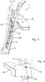
- Figs. 3 and 4 show a detail of Fig. 2 , wherein the light source 16 is in a mounted state.
- the holding plate 2 is mounted by the support arm 102 via a support 106 to the crossbeam 101 of the weaving machine 100.
- Other units can be mounted on the support 106, for example a holder 107 for holding a temple (not shown).
- a guide 108 for the insertion element 103 for example a rapier guide, and a cutter 109 are shown.
- the device 1 shown in Figs. 1 to 3 comprises the holding plate 2 and a number of weft feeder elements 4 mounted to the holding plate 2 so as to be moveable between a rest position and a presenting position.
- eight weft feeder elements 4 are mounted to the holding plate 2.
- more or less than eight weft feeder elements 4 are provided.
- seven weft feeder elements 4 of the device 1 are arranged in the rest position and the fourth weft feeder element 4 seen from the right in Fig. 1 is arranged in the presenting position.
- Each weft feeder element 4 has a weft thread guide 5 at its distal end, to which in use a weft thread 33 can be threaded.
- a weft thread 33 When threaded to the weft thread guide 5, the weft threads 33 extend between an associated weft thread guide 5 and a point 46 near the woven fabric (not shown).
- each weft feeder element 4 is connected via an associated drive mechanism 6 to an associated drive motor 8 (partially shown in Fig. 2 ) and guided by a guide structure 9.
- the drive mechanism 6 is an eccentric drive mechanism and comprises a crank 7. As shown in Fig. 2 , each crank 7 can move in an associated clearance 51 in the holding plate 2 that is bounded by two end stops 52 and 53 limiting a movement of the crank 7.
- weft feeder module 3 An assembly, comprising one weft feeder element 4 and the associated drive mechanism 6, the associated drive motor 8 and the associated guide structure 9 is also referred to as weft feeder module 3.
- weft feeder module 3 An assembly, comprising one weft feeder element 4 and the associated drive mechanism 6, the associated drive motor 8 and the associated guide structure 9 is also referred to as weft feeder module 3.
- the weft feeder modules 3 are attached in a staggered arrangement to the holding plate 2.
- the device 1 comprises a cable connection 49 for an energy supply to the light source 16 and to the weft feeder modules 3.
- the cable connection 49 can be connected to a control unit 70 (shown schematically in Fig. 1 ), for example the control unit of the weaving machine and/or an additional control unit (not shown) of which the device 1 is equipped.
- a pushbutton 34 is provided, which in embodiments is used for turning on and turning off the light source 16 as will be explained in more detail below.
- the weft insertion zone is defined as a zone comprising the presenting zone and the cutting zone.
- the device 1 further comprises the support arm 102 for mounting the holding plate 2 to the cross beam 101.
- an L-shaped support arm 102 is provided, wherein the support arm 102 has a first section 104 extending upwards from the cross beam 101 of the weaving machine 100 and a second section 105 extending transverse to the first section 104 (only partly visible in Fig. 1 ).
- the holding plate 2 is mounted to the second section 105.
- the first section 104 is inclined with respect to a vertical axis, the section still has a main extension direction in the vertical direction and is also referred to as vertical section.
- the device 1 is provided with a cover element 15 covering the second section 105 and an upper region of the holding plate 2, at which upper region the holding plate 2 is mounted to the second section 105.
- the device 1 is mounted to the weaving machine 100 such that - in the drawing plane of Fig. 1 - a right side of the device 1 is closer to a fabric (not shown in Fig. 1 ), and wherein the insertion element 103 in the drawing plane is moved from the left towards the right for an insertion of weft threads 33.
- the side of the device 1 closer to the fabric is referred to as "fabric-side" of the device 1.
- the light source 16 is mounted to the device 1 such that - when turned on - the light source 16 illuminates the weft insertion zone.
- the light source 16 is mounted at the fabric-side of the device 1, wherein the light source 16 is mounted adjacent to the weft feeder element 4, which in use is arranged closest to the fabric (which fabric is near the point 46, but not shown in the drawings), such that the light source 16 is arranged between said weft feeder element 4 and the fabric.
- the light source 16 is enclosed in a housing 60 formed integrally with a protrusion 43.
- the light source 16 is mounted via the protrusion 43 to the holding plate 2.
- the light source 16 is mounted to the holding plate 2 using two screws 61 extending through two through holes 62 provided in the holding plate 2.
- the holding plate 2 is provided with three through holes 62 so that the light source 16 can be mounted in two distinct positions to the holding plate 2 by means of two screws 61 cooperating with two of the through holes 62.
- a push button 63 (see Fig. 2 ) is provided, which can be used in addition or in alternative to the push button 34 for turning on or turning off the light source 16.
- the light source 16 is arranged above the thread feeding zone for illuminating the thread feeding zone.
- the light source 16 is arranged such that a beam of light emitted from the light source 16 reaches the thread feeding zone without crossing any of the weft feeder elements 4 arranged in the rest position and/or without crossing the holding plate 2, so that neither the weft feeder element 4 nor the holding plate 2 cause a shadow to be cast in the thread feeding zone.
- the light source 16 is a stroboscopic light source and/or is selectively operable in a stroboscopic mode, in which the stroboscopic light source 16 produces flashes of light, or in a continuous mode, in which a non-flashing light is produced.
- the pushbutton 34 on the holding plate and/or the pushbutton 63 on the housing 60 of the light source 16 is pushed.
- the pushbutton 34 on the holding plate and/or the pushbutton 63 on the housing 60 of the light source 16 is also used as a user interface for a communication with a control unit 70 configured for controlling an operation of the light source 16.
- the light source 16 is started or started in a stroboscopic mode by keeping the pushbutton 34, 63 pushed for a defined longer period, for example (but not limited) for at least five seconds.
- the light source 16 is caused to produce flashes of light with a flashing frequency, which is the same or an even multiple of the weaving frequency and at defined moments or angles in the weaving cycle.
- the light source 16 flashes at defined moments or angles in which the weft thread has to be presented.
- a flashing frequency and/or moments or angles in the weaving cycle, in which flashes are produced can also be altered using the pushbutton 34 and/or the pushbutton 63.
- the light source 16 flashes when the weft thread 33 has to be taken along by the insertion element 103, in particular the gripper.
- the light source 16 flashes when the weft thread 33 has to be cut by the weft cutter 109.
- the change in angle or moment in the weaving cycle depends on a duration the pushbutton 34, 63 is kept pushed.
- the light source 16 is turned off or switched into a continuous mode after a defined period, in which an operator has not taken any action. Thereby it is avoided that the weft insertion zone is permanently illuminated with the stroboscopic light source 16 in a stroboscopic mode giving the operator a false impression of a standstill of moving parts of the weaving machine.
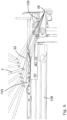
- Figs. 5 to 7 show a weft insertion zone illuminated by the light source 16 of the device 1 of Figs. 1 to 4 from above at a first instant, in which a weft thread 33 is presented to the insertion element 103, in particular the gripper, a second instant, in which the weft thread 33 previously presented is taken over by the insertion element 103, in particular the gripper, and a third instant, in which the weft thread 33 is taken over by the insertion element 103, in particular the gripper, is cut off from the fabric (not shown).
- an associated weft feeder element 4 in the exemplary presentation of Fig. 5 the fourth weft feeder element 4 seen from the right, is driven to move into the presenting position, so that the weft thread 33 extending between the point 46 near the woven fabric and the weft feeder element 4 is positioned in a path of the insertion element 103 and can be taken over by the insertion element 103 when moving the insertion element 103 towards a shed, i.e. to the right in the drawing plane of Fig. 5 .
- Illuminating the weft insertion zone with a stroboscopic light allows a visual inspection of a performance of the weft feeder element 4. In particular, it can be observed, whether the weft feeder element 4 is in the presenting position at a desired instant, i.e. a desired angle or moment in the weaving cycle.
- the insertion element 103 in particular a gripper, is moved towards the shed, i.e. to the right in the drawing plane of Fig. 6 .
- Illuminating the weft insertion zone with a stroboscopic light allows a visual inspection of the takeover of the weft thread 33 by the insertion element 103, which moves at high speed. In particular, it is possible to visually check at which position the weft thread 33 is actually taken over. Further, it is possible to visually check whether the takeover occurs in an intended way. In particular, it can be observed, whether the insertion element 103 reliably takes the presented weft thread 33 from the weft feeder element 4. It is also possible to observe when the weft feeder element 4, after the weft thread 33 has been taken over by the insertion element 103, moves from the presenting position towards an intermediate position between the presenting position and the rest position.
- the weft thread 33 is moved into the weft cutter 109.
- Illuminating the weft insertion zone with a stroboscopic light allows a visual inspection of the cutting of the weft thread 33 by the insertion element 103, wherein in particular a cutting moment, i.e., an instant or moment, in which the weft thread 33 is cut off the fabric for an insertion, is inspected.
- Fig. 8 shows the parts of the weaving machine 100 with the device 1 for selecting and presenting weft threads 33 as shown in Fig. 1 , wherein in contrast to Fig. 1 , the device 1 is shifted along a weaving frame, in particular shifted along the cross beam 101 together with the support 106.
- the light source 16 is arranged on the device 1, the light source 16 is shifted together with the device 1 and allows for an illumination of the thread feeding zone without the necessity of any additional set-up of the light source 16.
- Fig. 9 shows in a perspective view the parts of the weaving machine 100 of Fig. 1 , in particular the cross beam 101 of the weaving machine 100, the insertion element 103, which in the embodiment shown in Fig. 9 also is a gripper mounted on a rapier, and a second embodiment of a device 1 for selecting and presenting weft threads 33 to the insertion element 103.
- the device 1 shown in Fig. 9 is similar to the device 1 shown in Fig. 1 and for the same or similar elements, the same reference numbers will be used.
- the device 1 of Fig. 9 also comprises a holding plate 2, a support arm 102 for mounting the holding plate 2 to the weaving machine 100, more particular to the cross beam 101, and a light source 16.
- the device 1 of Fig. 9 comprises four instead of eight weft feeder elements 4, which are mounted to the holding plate 2.
- an inclination angle between the holding plate 2 and an insertion direction i.e. a movement direction of the insertion element 103 is larger for the device 1 of Fig. 9 than for the device 1 of Fig. 1 .
- a side of the device 1 and the holding-plate 2, which is closer to the fabric than the opposite side is still referred to as fabric-side.
- the light source 16 is arranged at the fabric-side.
- the device 1 comprises a camera 11.
- the camera 11 in the embodiment shown is arranged at the fabric-side of the device 1 and above the light source 16. More particular, the camera 11 is mounted to the second section 105 of the support arm 102 near a cover element 15 covering a second section 105 of the support arm 102 and an upper region of the holding plate 2.
- the light source 16 is mounted to the holding plate 2.
- Fig. 10 shows in disassembled state parts of a further embodiment of a device 1 for selecting and presenting weft threads to an insertion element comprising a support arm 102 and a light source 16 to be mounted to the support arm 102.
- the support arm 102 shown in Fig. 10 is similar in design to the support arm 102 shown in Fig. 1 .
- the support arm 102 comprises a first section 104, which extends upwards and is mountable via a support 106 to a crossbeam 101 (see Fig. 1 ) of a weaving machine.
- the support arm 102 further comprises a second section 105 extending transverse to the first section 104.
- the light source 16 is mounted to the second section 105 of the support arm 102, such that the first section 104 and the light source 16 are arranged at opposite sides of the device 1.
- a holding plate 2 (see Fig. 2 ) is attached to the second section 105 of the support arm 102.
- the weaving machine may comprise one or more further light sources mounted to the weaving machine.
- a light source may be arranged above the fabric or at the opposite side of the fabric where the gripper releases the weft thread.
- the further light sources may also be operable in a stroboscopic mode or in a continuous mode.
Landscapes
- Engineering & Computer Science (AREA)
- Textile Engineering (AREA)
- Looms (AREA)
Priority Applications (4)
| Application Number | Priority Date | Filing Date | Title |
|---|---|---|---|
| EP22185744.4A EP4310234B1 (fr) | 2022-07-19 | 2022-07-19 | Dispositif de sélection et de présentation de fils de trame |
| BE20230033A BE1030688B1 (nl) | 2022-07-19 | 2023-05-24 | Inrichting voor het selecteren en presenteren van weefdraden |
| PCT/EP2023/065836 WO2024017542A1 (fr) | 2022-07-19 | 2023-06-13 | Dispositif de sélection et de présentation de fils de trame |
| CN202380054690.6A CN119604651A (zh) | 2022-07-19 | 2023-06-13 | 用于选择和递送纬纱的装置 |
Applications Claiming Priority (1)
| Application Number | Priority Date | Filing Date | Title |
|---|---|---|---|
| EP22185744.4A EP4310234B1 (fr) | 2022-07-19 | 2022-07-19 | Dispositif de sélection et de présentation de fils de trame |
Publications (3)
| Publication Number | Publication Date |
|---|---|
| EP4310234A1 true EP4310234A1 (fr) | 2024-01-24 |
| EP4310234C0 EP4310234C0 (fr) | 2025-09-10 |
| EP4310234B1 EP4310234B1 (fr) | 2025-09-10 |
Family
ID=82656258
Family Applications (1)
| Application Number | Title | Priority Date | Filing Date |
|---|---|---|---|
| EP22185744.4A Active EP4310234B1 (fr) | 2022-07-19 | 2022-07-19 | Dispositif de sélection et de présentation de fils de trame |
Country Status (4)
| Country | Link |
|---|---|
| EP (1) | EP4310234B1 (fr) |
| CN (1) | CN119604651A (fr) |
| BE (1) | BE1030688B1 (fr) |
| WO (1) | WO2024017542A1 (fr) |
Citations (3)
| Publication number | Priority date | Publication date | Assignee | Title |
|---|---|---|---|---|
| EP0896075A2 (fr) * | 1997-08-07 | 1999-02-10 | NUOVA VAMATEX S.p.A. | Dispositif de présentation de fil de trame pour métiers à tisser |
| IT201900007548A1 (it) * | 2019-05-30 | 2020-11-30 | Textilma Ag | Macchina tessile con stroboscopio |
| CN112725989A (zh) * | 2020-12-29 | 2021-04-30 | 宁波宏大纺织仪器有限公司 | 无线同步频闪仪装置 |
-
2022
- 2022-07-19 EP EP22185744.4A patent/EP4310234B1/fr active Active
-
2023
- 2023-05-24 BE BE20230033A patent/BE1030688B1/nl active IP Right Grant
- 2023-06-13 WO PCT/EP2023/065836 patent/WO2024017542A1/fr not_active Ceased
- 2023-06-13 CN CN202380054690.6A patent/CN119604651A/zh active Pending
Patent Citations (3)
| Publication number | Priority date | Publication date | Assignee | Title |
|---|---|---|---|---|
| EP0896075A2 (fr) * | 1997-08-07 | 1999-02-10 | NUOVA VAMATEX S.p.A. | Dispositif de présentation de fil de trame pour métiers à tisser |
| IT201900007548A1 (it) * | 2019-05-30 | 2020-11-30 | Textilma Ag | Macchina tessile con stroboscopio |
| CN112725989A (zh) * | 2020-12-29 | 2021-04-30 | 宁波宏大纺织仪器有限公司 | 无线同步频闪仪装置 |
Also Published As
| Publication number | Publication date |
|---|---|
| BE1030688A1 (nl) | 2024-01-26 |
| CN119604651A (zh) | 2025-03-11 |
| EP4310234C0 (fr) | 2025-09-10 |
| BE1030688B1 (nl) | 2024-06-20 |
| EP4310234B1 (fr) | 2025-09-10 |
| WO2024017542A1 (fr) | 2024-01-25 |
Similar Documents
| Publication | Publication Date | Title |
|---|---|---|
| EP4310234A1 (fr) | Dispositif de sélection et de présentation de fils de trame | |
| EP1967630B1 (fr) | Machine à broder avec mécanismes de support et de découpe de fil supérieur | |
| RU2128254C1 (ru) | Ножницы для отрезания уточной нити на пневматическом ткацком станке | |
| US7036442B2 (en) | Yarn passing device of sewing machine for embroidery | |
| KR20140106431A (ko) | 재봉기 | |
| US6880472B2 (en) | Looper threading apparatus for sewing machine | |
| CN109706648B (zh) | 一种缝纫机上的自动剪线装置 | |
| EP1113100B1 (fr) | Mécanisme de guidage du fil d'aiguille pour une machine à coudre à point de chainette double | |
| JP4296319B2 (ja) | 照明装置付きミシン | |
| KR930001577Y1 (ko) | 재봉틀의 재봉지역 조명장치 | |
| CN1093192C (zh) | 链式缝缝纫机的线控制装置 | |
| US5113324A (en) | Sewing machine with a lamp | |
| US20070266919A1 (en) | Sewing Machine | |
| JPH0224160B2 (fr) | ||
| GB2285458A (en) | Sewing machine lower feed mechanism | |
| EP4310233A1 (fr) | Dispositif pour la sélection et la présentation de fils de trame | |
| JP3735760B2 (ja) | 糸繰り装置付ミシン | |
| US20140340871A1 (en) | Sewing Machine Uplight Assembly | |
| KR20080000510A (ko) | 단추달이 재봉기 | |
| JPH11253685A (ja) | ミシン | |
| CN117904801B (zh) | 一种独立送料剪线模块 | |
| US3443539A (en) | Sewing machine | |
| JP2546453B2 (ja) | ミシンの糸払い兼保持装置 | |
| AU2001254941B2 (en) | Tuft feeding mechanism | |
| JP2650516B2 (ja) | 二重環縫いミシンの糸切り装置 |
Legal Events
| Date | Code | Title | Description |
|---|---|---|---|
| PUAI | Public reference made under article 153(3) epc to a published international application that has entered the european phase |
Free format text: ORIGINAL CODE: 0009012 |
|
| STAA | Information on the status of an ep patent application or granted ep patent |
Free format text: STATUS: THE APPLICATION HAS BEEN PUBLISHED |
|
| AK | Designated contracting states |
Kind code of ref document: A1 Designated state(s): AL AT BE BG CH CY CZ DE DK EE ES FI FR GB GR HR HU IE IS IT LI LT LU LV MC MK MT NL NO PL PT RO RS SE SI SK SM TR |
|
| STAA | Information on the status of an ep patent application or granted ep patent |
Free format text: STATUS: REQUEST FOR EXAMINATION WAS MADE |
|
| 17P | Request for examination filed |
Effective date: 20240705 |
|
| RBV | Designated contracting states (corrected) |
Designated state(s): AL AT BE BG CH CY CZ DE DK EE ES FI FR GB GR HR HU IE IS IT LI LT LU LV MC MK MT NL NO PL PT RO RS SE SI SK SM TR |
|
| GRAP | Despatch of communication of intention to grant a patent |
Free format text: ORIGINAL CODE: EPIDOSNIGR1 |
|
| STAA | Information on the status of an ep patent application or granted ep patent |
Free format text: STATUS: GRANT OF PATENT IS INTENDED |
|
| INTG | Intention to grant announced |
Effective date: 20250422 |
|
| GRAS | Grant fee paid |
Free format text: ORIGINAL CODE: EPIDOSNIGR3 |
|
| GRAA | (expected) grant |
Free format text: ORIGINAL CODE: 0009210 |
|
| STAA | Information on the status of an ep patent application or granted ep patent |
Free format text: STATUS: THE PATENT HAS BEEN GRANTED |
|
| AK | Designated contracting states |
Kind code of ref document: B1 Designated state(s): AL AT BE BG CH CY CZ DE DK EE ES FI FR GB GR HR HU IE IS IT LI LT LU LV MC MK MT NL NO PL PT RO RS SE SI SK SM TR |
|
| REG | Reference to a national code |
Ref country code: GB Ref legal event code: FG4D |
|
| REG | Reference to a national code |
Ref country code: CH Ref legal event code: EP |
|
| REG | Reference to a national code |
Ref country code: DE Ref legal event code: R096 Ref document number: 602022021077 Country of ref document: DE |
|
| REG | Reference to a national code |
Ref country code: IE Ref legal event code: FG4D |
|
| U01 | Request for unitary effect filed |
Effective date: 20251010 |
|
| U07 | Unitary effect registered |
Designated state(s): AT BE BG DE DK EE FI FR IT LT LU LV MT NL PT RO SE SI Effective date: 20251017 |
|
| PG25 | Lapsed in a contracting state [announced via postgrant information from national office to epo] |
Ref country code: NO Free format text: LAPSE BECAUSE OF FAILURE TO SUBMIT A TRANSLATION OF THE DESCRIPTION OR TO PAY THE FEE WITHIN THE PRESCRIBED TIME-LIMIT Effective date: 20251210 |
|
| PG25 | Lapsed in a contracting state [announced via postgrant information from national office to epo] |
Ref country code: HR Free format text: LAPSE BECAUSE OF FAILURE TO SUBMIT A TRANSLATION OF THE DESCRIPTION OR TO PAY THE FEE WITHIN THE PRESCRIBED TIME-LIMIT Effective date: 20250910 |
|
| PG25 | Lapsed in a contracting state [announced via postgrant information from national office to epo] |
Ref country code: GR Free format text: LAPSE BECAUSE OF FAILURE TO SUBMIT A TRANSLATION OF THE DESCRIPTION OR TO PAY THE FEE WITHIN THE PRESCRIBED TIME-LIMIT Effective date: 20251211 |
|
| PG25 | Lapsed in a contracting state [announced via postgrant information from national office to epo] |
Ref country code: PL Free format text: LAPSE BECAUSE OF FAILURE TO SUBMIT A TRANSLATION OF THE DESCRIPTION OR TO PAY THE FEE WITHIN THE PRESCRIBED TIME-LIMIT Effective date: 20250910 |
|
| PG25 | Lapsed in a contracting state [announced via postgrant information from national office to epo] |
Ref country code: RS Free format text: LAPSE BECAUSE OF FAILURE TO SUBMIT A TRANSLATION OF THE DESCRIPTION OR TO PAY THE FEE WITHIN THE PRESCRIBED TIME-LIMIT Effective date: 20251210 |
|
| PG25 | Lapsed in a contracting state [announced via postgrant information from national office to epo] |
Ref country code: ES Free format text: LAPSE BECAUSE OF FAILURE TO SUBMIT A TRANSLATION OF THE DESCRIPTION OR TO PAY THE FEE WITHIN THE PRESCRIBED TIME-LIMIT Effective date: 20250910 |
|
| PG25 | Lapsed in a contracting state [announced via postgrant information from national office to epo] |
Ref country code: SM Free format text: LAPSE BECAUSE OF FAILURE TO SUBMIT A TRANSLATION OF THE DESCRIPTION OR TO PAY THE FEE WITHIN THE PRESCRIBED TIME-LIMIT Effective date: 20250910 |
|
| PG25 | Lapsed in a contracting state [announced via postgrant information from national office to epo] |
Ref country code: IS Free format text: LAPSE BECAUSE OF FAILURE TO SUBMIT A TRANSLATION OF THE DESCRIPTION OR TO PAY THE FEE WITHIN THE PRESCRIBED TIME-LIMIT Effective date: 20260110 |
|
| PG25 | Lapsed in a contracting state [announced via postgrant information from national office to epo] |
Ref country code: CZ Free format text: LAPSE BECAUSE OF FAILURE TO SUBMIT A TRANSLATION OF THE DESCRIPTION OR TO PAY THE FEE WITHIN THE PRESCRIBED TIME-LIMIT Effective date: 20250910 |
|
| PG25 | Lapsed in a contracting state [announced via postgrant information from national office to epo] |
Ref country code: SK Free format text: LAPSE BECAUSE OF FAILURE TO SUBMIT A TRANSLATION OF THE DESCRIPTION OR TO PAY THE FEE WITHIN THE PRESCRIBED TIME-LIMIT Effective date: 20250910 |