EP4310242B1 - Appareil de traitement de linge - Google Patents
Appareil de traitement de linge Download PDFInfo
- Publication number
- EP4310242B1 EP4310242B1 EP23215899.8A EP23215899A EP4310242B1 EP 4310242 B1 EP4310242 B1 EP 4310242B1 EP 23215899 A EP23215899 A EP 23215899A EP 4310242 B1 EP4310242 B1 EP 4310242B1
- Authority
- EP
- European Patent Office
- Prior art keywords
- filter
- laundry
- tub
- cabinet
- receiving device
- Prior art date
- Legal status (The legal status is an assumption and is not a legal conclusion. Google has not performed a legal analysis and makes no representation as to the accuracy of the status listed.)
- Active
Links
Images




Classifications
-
- D—TEXTILES; PAPER
- D06—TREATMENT OF TEXTILES OR THE LIKE; LAUNDERING; FLEXIBLE MATERIALS NOT OTHERWISE PROVIDED FOR
- D06F—LAUNDERING, DRYING, IRONING, PRESSING OR FOLDING TEXTILE ARTICLES
- D06F29/00—Combinations of a washing machine with other separate apparatus in a common frame or the like, e.g. with rinsing apparatus
- D06F29/005—Combinations of a washing machine with other separate apparatus in a common frame or the like, e.g. with rinsing apparatus the other separate apparatus being a drying appliance
-
- D—TEXTILES; PAPER
- D06—TREATMENT OF TEXTILES OR THE LIKE; LAUNDERING; FLEXIBLE MATERIALS NOT OTHERWISE PROVIDED FOR
- D06F—LAUNDERING, DRYING, IRONING, PRESSING OR FOLDING TEXTILE ARTICLES
- D06F25/00—Washing machines with receptacles, e.g. perforated, having a rotary movement, e.g. oscillatory movement, the receptacle serving both for washing and for centrifugally separating water from the laundry and having further drying means, e.g. using hot air
-
- D—TEXTILES; PAPER
- D06—TREATMENT OF TEXTILES OR THE LIKE; LAUNDERING; FLEXIBLE MATERIALS NOT OTHERWISE PROVIDED FOR
- D06F—LAUNDERING, DRYING, IRONING, PRESSING OR FOLDING TEXTILE ARTICLES
- D06F58/00—Domestic laundry dryers
- D06F58/02—Domestic laundry dryers having dryer drums rotating about a horizontal axis
-
- D—TEXTILES; PAPER
- D06—TREATMENT OF TEXTILES OR THE LIKE; LAUNDERING; FLEXIBLE MATERIALS NOT OTHERWISE PROVIDED FOR
- D06F—LAUNDERING, DRYING, IRONING, PRESSING OR FOLDING TEXTILE ARTICLES
- D06F58/00—Domestic laundry dryers
- D06F58/32—Control of operations performed in domestic laundry dryers
- D06F58/34—Control of operations performed in domestic laundry dryers characterised by the purpose or target of the control
- D06F58/36—Control of operational steps, e.g. for optimisation or improvement of operational steps depending on the condition of the laundry
- D06F58/38—Control of operational steps, e.g. for optimisation or improvement of operational steps depending on the condition of the laundry of drying, e.g. to achieve the target humidity
-
- D—TEXTILES; PAPER
- D06—TREATMENT OF TEXTILES OR THE LIKE; LAUNDERING; FLEXIBLE MATERIALS NOT OTHERWISE PROVIDED FOR
- D06F—LAUNDERING, DRYING, IRONING, PRESSING OR FOLDING TEXTILE ARTICLES
- D06F2103/00—Parameters monitored or detected for the control of domestic laundry washing machines, washer-dryers or laundry dryers
- D06F2103/28—Air properties
- D06F2103/32—Temperature
-
- D—TEXTILES; PAPER
- D06—TREATMENT OF TEXTILES OR THE LIKE; LAUNDERING; FLEXIBLE MATERIALS NOT OTHERWISE PROVIDED FOR
- D06F—LAUNDERING, DRYING, IRONING, PRESSING OR FOLDING TEXTILE ARTICLES
- D06F2103/00—Parameters monitored or detected for the control of domestic laundry washing machines, washer-dryers or laundry dryers
- D06F2103/28—Air properties
- D06F2103/34—Humidity
-
- D—TEXTILES; PAPER
- D06—TREATMENT OF TEXTILES OR THE LIKE; LAUNDERING; FLEXIBLE MATERIALS NOT OTHERWISE PROVIDED FOR
- D06F—LAUNDERING, DRYING, IRONING, PRESSING OR FOLDING TEXTILE ARTICLES
- D06F2103/00—Parameters monitored or detected for the control of domestic laundry washing machines, washer-dryers or laundry dryers
- D06F2103/28—Air properties
- D06F2103/36—Flow or velocity
-
- D—TEXTILES; PAPER
- D06—TREATMENT OF TEXTILES OR THE LIKE; LAUNDERING; FLEXIBLE MATERIALS NOT OTHERWISE PROVIDED FOR
- D06F—LAUNDERING, DRYING, IRONING, PRESSING OR FOLDING TEXTILE ARTICLES
- D06F2103/00—Parameters monitored or detected for the control of domestic laundry washing machines, washer-dryers or laundry dryers
- D06F2103/44—Current or voltage
-
- D—TEXTILES; PAPER
- D06—TREATMENT OF TEXTILES OR THE LIKE; LAUNDERING; FLEXIBLE MATERIALS NOT OTHERWISE PROVIDED FOR
- D06F—LAUNDERING, DRYING, IRONING, PRESSING OR FOLDING TEXTILE ARTICLES
- D06F2103/00—Parameters monitored or detected for the control of domestic laundry washing machines, washer-dryers or laundry dryers
- D06F2103/50—Parameters monitored or detected for the control of domestic laundry washing machines, washer-dryers or laundry dryers related to heat pumps, e.g. pressure or flow rate
-
- D—TEXTILES; PAPER
- D06—TREATMENT OF TEXTILES OR THE LIKE; LAUNDERING; FLEXIBLE MATERIALS NOT OTHERWISE PROVIDED FOR
- D06F—LAUNDERING, DRYING, IRONING, PRESSING OR FOLDING TEXTILE ARTICLES
- D06F2105/00—Systems or parameters controlled or affected by the control systems of washing machines, washer-dryers or laundry dryers
- D06F2105/16—Air properties
- D06F2105/24—Flow or velocity
-
- D—TEXTILES; PAPER
- D06—TREATMENT OF TEXTILES OR THE LIKE; LAUNDERING; FLEXIBLE MATERIALS NOT OTHERWISE PROVIDED FOR
- D06F—LAUNDERING, DRYING, IRONING, PRESSING OR FOLDING TEXTILE ARTICLES
- D06F2105/00—Systems or parameters controlled or affected by the control systems of washing machines, washer-dryers or laundry dryers
- D06F2105/26—Heat pumps
-
- D—TEXTILES; PAPER
- D06—TREATMENT OF TEXTILES OR THE LIKE; LAUNDERING; FLEXIBLE MATERIALS NOT OTHERWISE PROVIDED FOR
- D06F—LAUNDERING, DRYING, IRONING, PRESSING OR FOLDING TEXTILE ARTICLES
- D06F2105/00—Systems or parameters controlled or affected by the control systems of washing machines, washer-dryers or laundry dryers
- D06F2105/46—Drum speed; Actuation of motors, e.g. starting or interrupting
-
- D—TEXTILES; PAPER
- D06—TREATMENT OF TEXTILES OR THE LIKE; LAUNDERING; FLEXIBLE MATERIALS NOT OTHERWISE PROVIDED FOR
- D06F—LAUNDERING, DRYING, IRONING, PRESSING OR FOLDING TEXTILE ARTICLES
- D06F37/00—Details specific to washing machines covered by groups D06F21/00 - D06F25/00
- D06F37/26—Casings; Tubs
- D06F37/266—Gaskets mounted between tub and casing around the loading opening
-
- D—TEXTILES; PAPER
- D06—TREATMENT OF TEXTILES OR THE LIKE; LAUNDERING; FLEXIBLE MATERIALS NOT OTHERWISE PROVIDED FOR
- D06F—LAUNDERING, DRYING, IRONING, PRESSING OR FOLDING TEXTILE ARTICLES
- D06F58/00—Domestic laundry dryers
- D06F58/20—General details of domestic laundry dryers
-
- D—TEXTILES; PAPER
- D06—TREATMENT OF TEXTILES OR THE LIKE; LAUNDERING; FLEXIBLE MATERIALS NOT OTHERWISE PROVIDED FOR
- D06F—LAUNDERING, DRYING, IRONING, PRESSING OR FOLDING TEXTILE ARTICLES
- D06F58/00—Domestic laundry dryers
- D06F58/20—General details of domestic laundry dryers
- D06F58/206—Heat pump arrangements
-
- D—TEXTILES; PAPER
- D06—TREATMENT OF TEXTILES OR THE LIKE; LAUNDERING; FLEXIBLE MATERIALS NOT OTHERWISE PROVIDED FOR
- D06F—LAUNDERING, DRYING, IRONING, PRESSING OR FOLDING TEXTILE ARTICLES
- D06F58/00—Domestic laundry dryers
- D06F58/20—General details of domestic laundry dryers
- D06F58/22—Lint collecting arrangements
Definitions
- This invention relates to a laundry treatment apparatus.
- Laundry treatment apparatuses may wash and/or dry laundry, and may include, for example, washing machines, drying machines, and combination washing and drying machines.
- a laundry treatment apparatus capable of drying laundry may supply high temperature air (hot air), and may include exhaust type laundry treatment apparatuses and a circulation type (condensation type) laundry treatment apparatuses, based on an air flow method employed.
- a circulation type laundry treatment apparatus which re-circulates air from a laundry accommodation space in which laundry is received, may remove moisture (dehumidify) air discharged from the laundry accommodation space, and heat and resupply the air back into the laundry accommodation space.
- An exhaust type laundry treatment apparatus may supply heated air into a laundry accommodation space and exhaust air discharged from the laundry accommodation space to the outside of the laundry treatment apparatus, rather than resupplying the air back into the laundry accommodation space.
- a hot air supply device employed in a laundry treatment apparatus as described above may include a blower that discharges air from the laundry accommodation space and a heat exchanger that heats air moved by the blower.
- the blower may be located in front of the heat exchanger, such that air discharged from the laundry accommodation space sequentially passes through the blower and the heat exchanger and is resupplied into the laundry accommodation space. If the air discharged from the laundry accommodation space passes through only a portion of the heat exchanger, heat exchange efficiency of the laundry treatment apparatus may be impacted.
- US 7 020 986 B1 presents a drum type washing and drying machine that includes a cylindrical rotary drum provided with multiple drum perforations on the cylindrical surface thereof and having a rotating shaft in a horizontal or a slanted direction, a water tub, supported in a main body of the machine, for accommodating the rotary drum therein; an air circulation channel for recirculating air exhausted from the rotary drum back into the rotary drum via a dehumidification unit and a heating unit; and a lint trap device, installed in the air circulation channel, for filtering lint generated from laundry.
- the lint trap device at least includes a first and a second filter member capable of being detachably attached to each other, and the assembly of the first and the second filter member is freely attachably and detachably installed on a front upper portion of the main body in an approximately horizontal direction.
- EP 2 351 883 A2 presents a drying machine including housing, outer vessel supported in housing, rotating drum mounted in outer vessel to accommodate and dry clothing, heat pump device including heat exchanger for drying clothing in rotating drum, blower for blowing dry air, circulatory ventilation flue for connecting outer vessel to heat pump device to define circulation path through which dry air from blower circulates, and filter disposed in circulatory ventilation flue to prevent infiltration of dust components into heat exchanger, wherein filter and heat exchanger are disposed in upper space above outer vessel formed in housing, and filter, heat exchanger and blower are disposed in sequence along flow direction of dry air.
- One object of the present invention is to provide a laundry treatment apparatus which may achieve high drying efficiency.
- Another object of the present invention is to provide a laundry treatment apparatus which may achieve high heat exchange efficiency by allowing air moved by a blower to pass through the overall region of a heat exchanger
- Another object of the present invention is to provide a laundry treatment apparatus in which a hot air supply unit is located above a laundry accommodation unit in which laundry is accommodated, which may minimize increase in the volume of the laundry treatment apparatus.
- a further object of the present invention is to provide a laundry treatment apparatus which may ensure automated cleaning of a filter unit that serves to filter air to be supplied into a heat exchanger.
- the suction duct may be fixed to an upper circumferential surface of the tub, and the discharge duct is fixed to the gasket.
- the tub 2 may be arranged parallel to the ground, on which the cabinet 1 is supported, as shown in the drawing, or may be tilted by a prescribed angle with respect to the ground. In the case in which the tub 2 is tilted by a prescribed angle with respect to the ground, an inclination angle of the tub 2 may be less than 90 degrees.
- the tub 2 may also include an air discharge hole 25 perforated in an upper portion of a circumferential surface thereof for discharge of air from the tub 2.
- the air discharge hole 25 may be formed in a longitudinal direction of the tub 2 at a position spaced apart from an imaginary center line A of the tub 2 by a predetermined distance L1 (see FIG. 3 ). This may allow the interior air of the tub 2 to be easily discharged from the tub 2 through the air discharge hole 25 during rotation of the drum 3.
- the impurities may be moved to a lower surface of the tub 2 along an inner circumferential surface of the tub 2, which may prevent the impurities from being directed into the drum 3.
- the laundry treatment apparatus 100 may include a water supply and drain device to supply wash water into the tub 2 and to discharge wash water stored in the tub 2.
- the water supply and drain device may include a water supply device 29 to supply wash water into the tub 2, and a drain device 27 installed at the bottom of the tub 2 to discharge wash water stored in the tub 2.
- the water supply device 29 may supply water, supplied from an external water supply source into the tub 2.
- the water supply device 29 may include a water supply pipe connected to the water supply source and a water supply valve to open or close the water supply pipe.
- the drain device 27 may include a drain pipe communicating the interior of the tub 2 with the exterior of the cabinet 1, and an opening/closing device to open or close the drain pipe (e.g., a drain pump or a drain valve).
- a drain pipe communicating the interior of the tub 2 with the exterior of the cabinet 1, and an opening/closing device to open or close the drain pipe (e.g., a drain pump or a drain valve).
- the drum 3 may have a hollow cylindrical shape and be received within the tub 2.
- the drum 3 may be rotated within the tub 2 by a drive system 33, or motor 33 installed at an outer rear surface of the tub 2.
- the motor 33 may include a stator 335 fixed to the rear surface of the tub 2, a rotor 331 configured to be rotated via electromagnetic interaction with the stator 335, and a rotating shaft 333 penetrating the rear surface of the tub 2 to connect the rotor 331 and a rear surface of the drum 3 to each other.
- the drum 3 may include a drum opening 31 communicating with the laundry opening 11 and the tub opening 21. Thus, a user may introduce laundry into the drum 3 through the laundry opening 11, and remove laundry stored in the drum 3 from the cabinet 1.
- a detergent supply device 155 is installed within the cabinet 1 to store detergent to be supplied into the tub 2.
- the detergent supply device 155 may include a reservoir 1551 (see FIG. 5 ) in the form of a drawer that may be withdrawn from the cabinet 1, a detergent supply pipe 1553 to guide detergent stored in the reservoir 1551 into the tub 2, and a reservoir handle 1555 located at one side of the control panel 15 to allow the user to withdraw the reservoir 1551 from the cabinet 1.
- Water may be supplied into the reservoir 1551 from the external water supply source through the water supply device 29.
- detergent stored in the reservoir 1551 may be supplied, along with the water, into the tub 2 through the detergent supply pipe 1553.
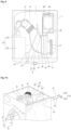
- the circulation passage may include a suction duct 41 fitted into the air discharge hole 25 of the tub 2, a connection duct 43 to connect the suction duct 41 and the blower 49, the heat exchanger 45 secured to the connection duct 43, and a discharge duct 47 to connect the blower 49 and the gasket 23.
- the suction duct 41 may be a path into which the interior air of the tub 2 is discharged through the air discharge hole 25 perforated in a rear portion of the circumferential surface of the tub 2.
- the suction duct 41 may be formed of a vibration insulating material (e.g., rubber) to prevent vibration of the tub 2 generated during rotation of the drum 3 from being transferred to the connection duct 43 and the heat exchanger 45 through the suction duct 41.
- the suction duct 41 may include bellows.
- the bellows may be formed along the entire suction duct 41, or may be formed at a portion of the suction duct 41 (i.e. a coupling portion with the connection duct 43).
- the heat exchanger 45 may be a heat pump.
- the heat exchanger 45 may include an evaporator 451, a condenser 453, a compressor 455, and an expander (i.e. expansion valve).
- the evaporator 451 and the condenser 453 may be fixed within the connection duct 43, whereas the compressor 455 may be mounted at the outside of the connection duct 43.
- the compressor 455, the evaporator 451, the condenser 453, and the expander may be connected to each other via a refrigerant pipe 459, and circulation of refrigerant may be realized by the compressor 455.
- the hot air supply device 4 may further include a compressor support member 457 installed at the exterior of the connection duct 43 to support the compressor 455.
- the compressor support member 457 may be installed at the connection duct 43 to support the bottom of the compressor 455.
- the suction duct 41, the connection duct 43 in which the evaporator 451 and the condenser 453 of the heat exchanger 45 are mounted, the discharge duct 47, and the blower 49 may be integrally assembled, whereas the compressor 455 of the heat exchanger 45 may be secured to the connection duct 43 via the compressor support member 457 that is also secured to the connection duct 43.
- Provision of the hot air supply device 4 in the form of a module may ensure easy assembly of the hot air supply device 4 and the cabinet 1.
- connection of the evaporator 451 and the condenser 453 to the compressor 455 via the refrigerant pipe 459 may be more easily implemented than assembling respective constituent elements of the hot air supply device 4 within the cabinet 1.
- the evaporator 451 refrigerant is evaporated by absorbing heat from air introduced into the connection duct 43.
- the evaporator 451 may implement cooling of the air as well as removal of moisture contained in the air (i.e. dehumidification and condensation of the air).
- condensed water may remain in the connection duct 43. This condensed water remaining in the connection duct 43 may be unintentionally directed to laundry during drying.
- the laundry treatment apparatus 100 may further include a device to discharge the condensed water from the connection duct 43.
- the circulation path 41, 43 and 47 as shown in FIG. 3 , is arranged in a diagonal direction of an upper portion of the tub 2.
- the compressor 455 may be located in a space between the circulation path 41, 43 and 47 and the cabinet 1 in the space above the tub 2. This may contribute to efficient utilization of the space above the circumferential surface of the tub 2, thereby preventing an increase in the height or volume of the laundry treatment apparatus 100
- the discharge duct 47 may guide the air discharged from the connection duct 43 into the tub 2 through the blower 49.
- One end of the discharge duct 47 may be fixed to the blower 49 and the other end of the discharge duct 47 may be connected to a duct connection hole 231 formed in the gasket 23.
- at least one of the gasket 23 or the discharge duct 47 may be formed of a vibration insulating material (or an elastic material).
- the blower 49 may be located between the heat exchanger 45 and the discharge duct 47.
- the blower 49 may cause air to pass through the heat exchanger 45 by generating negative pressure at the rear side of the heat exchanger 45 (toward the discharge duct 47), rather than generating positive pressure at the front side of the heat exchanger 45 (toward the suction duct 41).
- the blower 49 is located in front of the heat exchanger 45 to forcibly blow air toward the heat exchanger 45 (to generate positive pressure at the front side of the heat exchanger 45)
- the flow rate of air per cross section of the connection duct 43 may be inconsistent according to a position of the connection duct 43, which may result in deterioration of heat exchange efficiency.
- the above-described problem may be solved as the blower 49 may be located between the heat exchanger 45 and the discharge duct 47 (to allow air to sequentially pass through the heat exchanger 45 and the blower 49).
- connection duct 43 As the connection duct 43 is disposed on an upper portion of the circumferential surface of the tub 2, there may be a difference between the size of a space in which the evaporator 451 is located and the size of a space in which the condenser 453 is located. That is, as shown in FIG. 3 , a height H1 of the connection duct 43 with regard to an installation space of the evaporator 451 may be less than a height H2 of the connection duct 43 with regard to an installation space of the condenser 453.
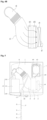
- the filter guide 431 may communicate the interior of the connection duct 43 with the filter separation/coupling passage 157. More specifically, the filter guide 431 may include a section that protrudes from an outer circumferential surface of the connection duct 43 and is connected to the filter separation/coupling passage 157, and a section that is located inside the connection duct 43 and configured to receive only an edge of the filter device 5.
- the filter separation/coupling passage 157 may be formed to penetrate the cabinet 1 or to penetrate the control panel 15.
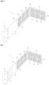
- the filter device 5 may further include frame coupling portions 581 and 583 to secure the second frame 57 to the first frame 55.
- the frame coupling portions 581 and 583 may include a boss 581 formed at one of the body 51 or the second frame 57, and a receiving recess 583 formed in the other of the body 51 or the second frame 57 such that the boss 581 is inserted into the receiving recess 583.
- FIG. 6 shows one example in which the boss 581 is formed at the body 51 and the receiving recess 583 is formed in an outer periphery of the second frame 57.
- Impurities remaining on the first filter 553 and the second filter 573 of the filter frames 55 and 57 may be removed by the impurity removal device 6.
- the impurity removal device 6 may further include a water supplier 63, which supplies water into the connection duct 43 to discharge impurities remaining in the connection duct 43 to the outside of the connection duct 43.
- the water supplier 63 may connect the connection duct 43 and the water supply source provided inside or outside of the laundry treatment apparatus 100 to each other, thereby supplying water into the connection duct 43 to discharge the impurities remaining in the connection duct 43 to the outside of the tub 2.
- connection duct 43 may be discharged from the connection duct 43 through a separate path that communicates the connection duct 43 with the outside of the cabinet 1 or a separate path that connects the connection duct 43 and the drain device 27 to each other.
- the water supplier 63 may supply water into the heat exchanger 45 to remove impurities remaining on a surface of the heat exchanger 45.
- the impurities accumulated on the heat exchanger 45 may have higher possibility of accumulation on a surface of the evaporator 451 than possibility of accumulation on a surface of the condenser 453. Therefore, the water supplier 63 may include a nozzle configured to eject water to the evaporator 451 and a path that connects the nozzle and the water supply source to each other.
- the nozzle may be oriented to obliquely eject water onto the surface of the evaporator 451 by a prescribed angle, and impurities separated from the surface of the evaporator 451 by the water ejected from the nozzle may be discharged outward from the cabinet 1 through the path that communicates the connection duct 43 with the outside of the cabinet 1 or the path that connects the connection duct 43 and the drain device 27 to each other.
- the impurities separated from the surface of the evaporator 451 by the water ejected from the nozzle may be introduced into the tub 2 through the suction duct 41, and thereafter be discharged outward from the cabinet 1 through the drain device 27.
- the user may withdraw the detergent reservoir 1551 from the cabinet 1 to put detergent into the detergent reservoir 1551, and thereafter may introduce the detergent reservoir 1551 into the cabinet 1.
- the filter device 5 may be withdrawn from the cabinet 1 along with the detergent reservoir 1551, impurities remaining on the filter device 5 may be removed from the filter device 5 by the scraper 61 when the user withdraws the detergent reservoir 1551 from the cabinet 1 for washing of laundry. Accordingly, additional cleaning of the filter device 5.
- the body 51 of the filter device 5 may be connected to the detergent reservoir 1551. In this case, if the user withdraws the detergent reservoir 1551 from the cabinet, the filter device 5 may be automatically withdrawn from the cabinet 1.
- the laundry treatment apparatus 100 may further include a sensor installed within the connection duct 43 at a position between the evaporator 451 and the condenser 453 to measure the temperature of air.
- the sensor may measure the temperature of air dehumidified inside the connection duct 43, and transmit the measured temperature to a controller.
- the controller may determine dryness of laundry by comparing measured temperature data with predetermined temperature data (experimentally set temperature data on a per dryness basis).
- the sensor may be located between the evaporator 451 and the condenser 453 to prevent impurities from being accumulated on the sensor, thereby preventing the sensor from failing to acquire accurate temperature data.
- impurities may be introduced into the evaporator 451 despite the presence of the filter device 5 used to filter air to be introduced into the evaporator 451.
- impurities may be accumulated on the sensor, thereby preventing the sensor from sensitively measuring the temperature of air.
- the evaporator 451 may serve as a filter to catch the impurities even if the impurities are introduced into the evaporator 451. Consequently, this arrangement may prevent problems caused when the sensor is located in front of the evaporator 451.
- the fasteners 7, 81 and 83 may be fixed to the cabinet 1 to secure the hot air supply device 4 to an upper surface of the tub 2.
- the fasteners may include a pressure member 7 that applies pressure to the hot air supply device 4 toward the tub 2, and support members 81 and 83 to support the bottom of the hot air supply device 4.
- the pressure member 7 may be located on the hot air supply unit 4. One end of the pressure member 7 may be fixed to a front surface of the cabinet 1 and the other end of the pressure member 7 may be fixed to a rear surface of the cabinet 1. As such, the pressure member 7 may prevent the hot air supply device 4 from being separated from the upper surface of the tub 2 by external force.
- the pressure member 7, as shown in FIG. 9B may include a bar-shaped pressure body 71, and fastening pieces 73 respectively located at opposite ends of the pressure body 71 and fastened to the cabinet 1.
- the pressure body 71 may be fixed to the cabinet 1 via the fastening pieces 73, thereby supporting an upper surface of the connection duct 43 or being fixed to the upper surface of the connection duct 43.
- the pressure body 71 may include a bent portion 711 to prevent the pressure body 71 from coming into contact with the compressor 455. This is because, if the pressure body 71 comes into contact with the compressor 455, vibration generated in the compressor 455 may be transmitted to the cabinet 1 through the pressure body 71, thereby causing noise or vibration.
- the bent portion 711 may not be provided at the pressure body 71, depending on the arrangement of the hot air supply device 4 and other devices located above the tub 2.
- the pressure member 7 may further include flange portions 75 provided at opposite ends of the pressure body 71 to increase the strength of the pressure body 71.
- a pair of flange portions 75 may be arranged in a longitudinal direction of the pressure body 71.
- the above-described pressure member 7 may be located above the connection duct 43, and may prevent the hot air supply device 4 from being moved away from the tub 2. However, the pressure member 7 cannot prevent transmission of vibration from the tub 2 to the hot air supply device 4. Accordingly, the fasteners may include the support members 81 and 83 configured to maintain a constant gap between a lower surface of the hot air supply device 4 and the tub 2.
- the support members may include first support members 81 secured to the cabinet 1 to support the connection duct 43 or the blower 49 and/or second support members 83 configured to secure the compressor support member 457 to the cabinet 1.
- the first support members 81 may be located in a space between the upper surface of the tub 2 and a lower surface of the circulation path 41, 43 and 45.
- the first support members 81 may include support bars 811 configured to secure the connection duct 43 or the blower 49 to the cabinet 1.
- One or more support bars 811 may be provided. Provision of two or more support bars 811 may provide more stable support to the connection duct 43 or the blower 49. Each of the support bars 811 may penetrate the cabinet 1 at a position above the door 13, and a first vibration insulator 813 may be provided at a circumferential surface of the support bar 811 coming into contact with the cabinet 1 to prevent vibration of the hot air supply device 4 from being transmitted to the cabinet 1 and to prevent vibration of the cabinet 1 generated during transportation of the laundry treatment apparatus 100 from being transmitted to the hot air supply device 4.
- the first vibration insulator 813 may be formed of ethylene propylene diene monomer (EPDM) rubber, but it is unnecessary to limit the material of the first vibration insulator 813 to the aforementioned EPDM rubber so long as the first vibration insulator 813 may provide the above-described function.
- EPDM ethylene propylene diene monomer
- the second support members 83 may secure the compressor support member 457 to the cabinet 1.
- the second support members 83 may include compressor support bars 831 and second vibration insulators 833. As shown in FIG. 10 , each of the compressor support bars 831 may penetrate the rear surface of the cabinet 1 and may be inserted into a hole 4573 formed in the compressor support member 457.
- One or more compressor support bars 831 may be provided, and two or more compressor support bars 831 may more stably support the compressor 455.
- the second vibration insulator 833 may be provided on a circumferential surface of the compressor support bar 831 coming into contact with the cabinet 1.
- the second vibration insulator 833 may include a cabinet coupling portion 8331 coupled to the cabinet 1 and a bar through-hole 8333 perforated in the cabinet coupling portion 8331 such that the compressor support bar 831 is inserted into the bar through-hole 8333.
- the second vibration insulator 833 may be formed of EPDM rubber, but it is unnecessary to limit the material of the second vibration insulating portion to the EPDM rubber.
- the laundry treatment apparatus 100 may include a first controller 911 to control at least one of rotation of the drum 3, supply and drainage of wash water, and/or the control panel 15, and a second controller 931 to control operation of the hot air supply device 4, the first controller 911 and the second controller 931 being separate from each other.
- FIG. 11 shows one example of the first controller 911 for control of rotation of the drum 3 and control of supply and drainage of wash water (control of the water supply valve and the drain valve) and the second controller 931 for control of operation of the hot air supply device 4.
- the use of two controllers 911 and 931 may prevent deterioration in the performance of the laundry treatment apparatus 100 caused when a main controller suffers from overload of data to be processed when the single main controller has to control all of a drive system (e.g., the motor 33 provided for rotation of the drum 3), the water supply and drain devices 27 and 29 of the tub 2, and the hot air supply device 4.
- a drive system e.g., the motor 33 provided for rotation of the drum 3
- the water supply and drain devices 27 and 29 of the tub 2 e.g., the hot air supply device 4.
- the first controller 911 mainly controls a washing cycle for washing of laundry via control of the drive system 33 and the water supply and drain devices 27 and 29 (i.e. a cycle during which contaminants of laundry are separated via rotation of the drum 3 and supply and drainage of wash water), and the second controller 931 mainly controls a drying cycle for drying of laundry via control of the hot air supply device 4 (i.e. a cycle during which hot air is supplied to laundry via the heat exchanger 45 and the blower 49).
- operation of the laundry treatment apparatus may terminate when the drying cycle terminates, and therefore control of the power supply device may be conducted by the second controller 931.
- the first controller 911 and the second controller 931 may be physically separated from each other by a first printed circuit board (PCB) 91 and a second PCB 93.
- PCB printed circuit board
- the first PCB 91 may be integrally mounted to the control panel 15, and the second PCB 93 may be disposed on the control panel 15 and be separably coupled to the first PCB 91.
- the controllers 911 and 931 mounted on the respective PCBs 91 and 93 may be electrically connected to each other via a connector 95. That is, the first PCB 91 and the second PCB 93 included in the laundry treatment apparatus 100 may be separable from each other, and may be connected to each other via the connector 95 to enable data exchange (data communication) between the first controller 911 and the second controller 931 as needed.
- the laundry treatment apparatus designed to implement only a washing function may be modified into a laundry treatment apparatus capable of implementing a drying function as well as the washing function.
- the laundry treatment apparatus in which the hot air supply device 4 is controlled by the first controller 911 may be modified in such a manner that the hot air supply device 4 is controlled by the second controller 931.
- Examples of data transmitted from the first controller 911 to the second controller 931 may include data regarding whether or not a washing cycle has terminated and data regarding the quantity of laundry stored in the drum 3 (laundry quantity data). Examples of data transmitted from the second controller 931 to the first controller 911 may include a signal indicating termination of operation of the hot air supply device 4, the temperature of air to be supplied into the tub 2, and dryness of laundry stored in the drum 3.
- the first controller 911 may display the data transmitted from the second controller 931 on the display device 153 provided at the control panel 15 as needed.
- examples of data exchanged between the first controller 911 and the second controller 931 may include an operation request signal of the first controller 911 and an operation request signal of the second controller 931.
- the first controller 911 may transmit a signal to request the second controller 931 for temporary operation of the hot air supply device 4.
- the second controller 931 may transmit a signal to request the first controller 911 for temporary operation of the drive system 33 or the water supply and drain devices 27 and 29.
- the data storage medium 97 may be provided at the first PCB 91.
- the second controller 931 may share the data storage medium 97 provided at the first PCB 91 because the second PCB 93 may be selectively coupled to the first PCB 91 as needed.
- the second controller 931 determines whether or not laundry reaches target dryness (S60). Determination of dryness (S60) may be conducted as a sensor measures data regarding the temperature and humidity of air discharged from the tub 2 and the second controller 931 compares the data transmitted from the sensor with predetermined reference data on a per laundry quantity basis.
- any reference in this specification to "one embodiment,” “an embodiment,” “example embodiment,” etc. means that a particular feature, structure, or characteristic described in connection with the embodiment is included in at least one embodiment of the invention.
- the appearances of such phrases in various places in the specification are not necessarily all referring to the same embodiment.
Landscapes
- Engineering & Computer Science (AREA)
- Textile Engineering (AREA)
- Detail Structures Of Washing Machines And Dryers (AREA)
- Accessory Of Washing/Drying Machine, Commercial Washing/Drying Machine, Other Washing/Drying Machine (AREA)
Claims (14)
- Appareil de traitement de linge (100) pour sécher et laver du linge, comportant :- une carrosserie (1) ayant une ouverture pour le linge (11) formée dans celle-ci ;- un dispositif de réception de linge prévu dans la carrosserie (1) et configuré pour recevoir du linge dans celui-ci à travers l'ouverture pour le linge (11) formée dans la carrosserie (1), une cuve (2) reçue à l'intérieur de la carrosserie (1) pour stocker de l'eau de lavage dans celle-ci et un tambour (3) reçu à l'intérieur de la cuve (2) de façon à pouvoir tourner, destiné à stocker du linge dans celui-ci ;- un panneau de commande (15) couplé à la carrosserie (1) au-dessus de l'ouverture pour le linge (11) ;- un dispositif d'alimentation en détergent (155) installé à l'intérieur de la carrosserie (1) pour stocker du détergent à fournir à la cuve (2) ;- un dispositif d'alimentation en air chaud (4) incluant : un passage de circulation (41, 43, 47) configuré pour guider de l'air évacué du dispositif de réception de linge et pour réintroduire l'air dans le dispositif de réception de linge, un échangeur de chaleur (45) agencé dans le passage de circulation (41, 43, 47) et une soufflante (49) configurée pour faire circuler de l'air depuis un intérieur du dispositif de réception de linge à travers le passage de circulation (41, 43, 47) et pour le faire retourner dans le dispositif de réception de linge ;- un dispositif à filtre (5) positionné dans le passage de circulation (41, 43, 47) pour filtrer l'air s'écoulant jusqu'à l'échangeur de chaleur (45), dans lequel le dispositif à filtre (5) peut être retiré du passage de circulation (41, 43, 47) à travers une partie correspondante de la carrosserie (1) ;- un passage de séparation/couplage de filtre (157) qui pénètre dans la carrosserie (1) et par lequel le dispositif à filtre (5) passe ;- un guide de filtre (431) reliant le passage de séparation/couplage de filtre (157) et le passage de circulation (41, 43, 47), dans lequel le guide de filtre (431) est configuré pour guider le dispositif à filtre (5) dans le passage de circulation (41, 43, 47) et à l'extérieur de celui-ci ;caractérisé en ce que le passage de circulation (41, 43, 47) s'étend dans une direction diagonale à travers la partie supérieure du dispositif de réception de linge, et en ce quele passage de séparation/couplage de filtre (157) est formé pour pénétrer dans la carrosserie (1) dans un espace situé entre le panneau de commande (15) et le dispositif d'alimentation en détergent (155) agencés parallèlement l'un à l'autre.
- Appareil (100) selon la revendication 1, dans lequel le dispositif à filtre (5) comporte :une poignée (53) configurée pour être en appui dans le passage de séparation/couplage de filtre (157) ;un corps de filtre (51), dans lequel la poignée (53) est installée sur le corps de filtre (51) ;un premier châssis (55) fixé au corps (51) et supportant un premier filtre (553) configuré pour filtrer l'air ; etun second châssis (57) couplé au premier châssis (55) de manière rotative et séparable et supportant un second filtre (573) configuré pour filtrer l'air.
- Appareil (100) selon la revendication 2, dans lequel le corps de filtre (51) est raccordé entre la poignée (53) et le premier châssis (55).
- Appareil (100) selon la revendication 3, dans lequel au moins un élément parmi le premier châssis (55), le second châssis (57) et le corps de filtre (51) est formé d'un matériau élastique.
- Appareil (100) selon la revendication 3 ou 4, dans lequel le corps de filtre (51) inclut une partie de support élastique (59) constituant une partie du corps de filtre (51), et dans lequel la partie de support élastique (59) inclut une pluralité de cannelures formées sur une surface du corps de filtre (51).
- Appareil (100) selon l'une quelconque des revendications précédentes, comportant en outre un dispositif de retrait d'impuretés (6) configuré pour retirer des impuretés accumulées sur le filtre (553, 573), dans lequel le dispositif de retrait d'impuretés (6) comporte un racleur (61) couplé au guide de filtre (431) pour séparer les imputés du dispositif à filtre (5) lorsque le dispositif à filtre (5) est extrait du passage de circulation ou inséré dans celui-ci.
- Appareil (100) selon l'une quelconque des revendications précédentes, dans lequel le dispositif à filtre (5) est installé de manière à être extrait de la carrosserie simultanément à l'extraction du dispositif d'alimentation en détergent (155).
- Appareil (100) selon l'une quelconque des revendications précédentes, dans lequel le passage de circulation (41, 43, 47) guide l'air à l'extérieur du dispositif de réception de linge depuis une zone arrière du dispositif de réception de linge et pour le faire retourner dans le dispositif de réception de linge sur une zone avant du dispositif de réception de linge, la zone avant étant orientée pour faire face à l'ouverture pour le linge (11).
- Appareil (100) selon l'une quelconque des revendications précédentes, dans lequel le passage de circulation (41, 43, 47) inclut :un conduit d'aspiration (41) fixé à une surface arrière du dispositif de réception de linge, dans lequel le conduit l'aspiration (41) guide l'air depuis un intérieur du dispositif de réception de linge dans le passage de circulation (41, 43, 47) ;un conduit d'évacuation (47) fixé à une surface avant du dispositif de réception de linge, dans lequel le conduit d'évacuation (47) évacue l'air du passage de circulation (41, 43, 47) pour retourner dans le dispositif de réception de linge ; etun conduit de liaison (43) reliant le conduit d'aspiration (41) et le conduit d'évacuation (47),dans lequel l'échangeur de chaleur (45) est positionné dans le conduit de liaison (43), etdans lequel la soufflante (49) est positionnée entre l'échangeur de chaleur (45) et le conduit d'évacuation (47).
- Appareil (100) selon la revendication 9, dans lequel la cuve (2) a une ouverture de cuve (21) dirigée vers l'ouverture pour le linge (11) formée dans la carrosserie (1), le tambour (3) est configuré pour recevoir du linge dans celui-ci à travers l'ouverture de cuve (21), et le dispositif de réception de linge inclut :
un joint (23) s'étendant entre l'ouverture de cuve (21) et l'ouverture pour le linge (11) de manière à empêcher une fuite d'eau de lavage à partir de la cuve (2). - Appareil (100) selon la revendication 10, dans lequel le conduit d'aspiration (41) est fixé à une surface circonférentielle supérieure de la cuve (2), et le conduit d'évacuation (47) est fixé au joint (23).
- Appareil (100) selon la revendication 11, dans lequel le conduit d'aspiration (41) et le joint (23) sont des éléments d'isolation contre les vibrations.
- Appareil (100) selon l'une quelconque des revendications précédentes, dans lequel le passage de circulation (41, 43, 47) est fixé à une surface circonférentielle extérieure supérieure du dispositif de réception de linge et permet une isolation contre les vibrations pour l'échangeur de chaleur (45) et le dispositif de réception de linge.
- Appareil (100) selon la revendication 1, dans lequel le dispositif à filtre (5) comporte :une poignée (53) reçue dans le passage de séparation/couplage de filtre (157) ;un corps de filtre (51) agencé dans le guide de filtre (431) ;une partie de support élastique (59) reliant la poignée (53) et le corps de filtre (51) pour supporter élastiquement le corps de filtre (51) ; etun châssis de filtre s'étendant à partir du corps de filtre dans le passage de circulation,un filtre supporté dans le châssis de filtre pour capturer des impuretés dans l'air s'écoulant à travers le passage de circulation, le châssis de filtre comportant :un premier châssis (55) relié au corps de filtre (51) et supportant un premier filtre (553) configuré pour filtrer l'air, etun second châssis (57) couplé au premier châssis (55) de manière rotative et séparable et supportant un second filtre (573) configuré pour filtrer l'air.
Priority Applications (2)
| Application Number | Priority Date | Filing Date | Title |
|---|---|---|---|
| EP25164134.6A EP4545699B1 (fr) | 2013-01-25 | 2014-01-20 | Appareil de traitement de linge |
| EP25164129.6A EP4545698A3 (fr) | 2013-01-25 | 2014-01-20 | Appareil de traitement de linge |
Applications Claiming Priority (6)
| Application Number | Priority Date | Filing Date | Title |
|---|---|---|---|
| KR1020130008615A KR101995429B1 (ko) | 2013-01-25 | 2013-01-25 | 의류처리장치 |
| KR1020130008499A KR20140095740A (ko) | 2013-01-25 | 2013-01-25 | 의류처리장치 |
| KR1020130008501A KR102017695B1 (ko) | 2013-01-25 | 2013-01-25 | 의류처리장치 |
| KR1020130013293A KR102129793B1 (ko) | 2013-02-06 | 2013-02-06 | 의류처리장치 |
| EP14743219.9A EP2948583B1 (fr) | 2013-01-25 | 2014-01-20 | Appareil de traitement de linge |
| PCT/KR2014/000543 WO2014115999A1 (fr) | 2013-01-25 | 2014-01-20 | Appareil de traitement de linge |
Related Parent Applications (1)
| Application Number | Title | Priority Date | Filing Date |
|---|---|---|---|
| EP14743219.9A Division EP2948583B1 (fr) | 2013-01-25 | 2014-01-20 | Appareil de traitement de linge |
Related Child Applications (4)
| Application Number | Title | Priority Date | Filing Date |
|---|---|---|---|
| EP25164129.6A Division EP4545698A3 (fr) | 2013-01-25 | 2014-01-20 | Appareil de traitement de linge |
| EP25164129.6A Division-Into EP4545698A3 (fr) | 2013-01-25 | 2014-01-20 | Appareil de traitement de linge |
| EP25164134.6A Division-Into EP4545699B1 (fr) | 2013-01-25 | 2014-01-20 | Appareil de traitement de linge |
| EP25164134.6A Division EP4545699B1 (fr) | 2013-01-25 | 2014-01-20 | Appareil de traitement de linge |
Publications (4)
| Publication Number | Publication Date |
|---|---|
| EP4310242A2 EP4310242A2 (fr) | 2024-01-24 |
| EP4310242A3 EP4310242A3 (fr) | 2024-02-28 |
| EP4310242C0 EP4310242C0 (fr) | 2025-07-02 |
| EP4310242B1 true EP4310242B1 (fr) | 2025-07-02 |
Family
ID=51221367
Family Applications (6)
| Application Number | Title | Priority Date | Filing Date |
|---|---|---|---|
| EP23215899.8A Active EP4310242B1 (fr) | 2013-01-25 | 2014-01-20 | Appareil de traitement de linge |
| EP25164129.6A Pending EP4545698A3 (fr) | 2013-01-25 | 2014-01-20 | Appareil de traitement de linge |
| EP25164134.6A Active EP4545699B1 (fr) | 2013-01-25 | 2014-01-20 | Appareil de traitement de linge |
| EP14743476.5A Active EP2948584B1 (fr) | 2013-01-25 | 2014-01-20 | Appareil de traitement du linge |
| EP14743079.7A Active EP2948582B1 (fr) | 2013-01-25 | 2014-01-20 | Appareil de traitement du linge |
| EP14743219.9A Active EP2948583B1 (fr) | 2013-01-25 | 2014-01-20 | Appareil de traitement de linge |
Family Applications After (5)
| Application Number | Title | Priority Date | Filing Date |
|---|---|---|---|
| EP25164129.6A Pending EP4545698A3 (fr) | 2013-01-25 | 2014-01-20 | Appareil de traitement de linge |
| EP25164134.6A Active EP4545699B1 (fr) | 2013-01-25 | 2014-01-20 | Appareil de traitement de linge |
| EP14743476.5A Active EP2948584B1 (fr) | 2013-01-25 | 2014-01-20 | Appareil de traitement du linge |
| EP14743079.7A Active EP2948582B1 (fr) | 2013-01-25 | 2014-01-20 | Appareil de traitement du linge |
| EP14743219.9A Active EP2948583B1 (fr) | 2013-01-25 | 2014-01-20 | Appareil de traitement de linge |
Country Status (6)
| Country | Link |
|---|---|
| US (3) | US9290885B2 (fr) |
| EP (6) | EP4310242B1 (fr) |
| CN (3) | CN104919105B (fr) |
| AU (3) | AU2014210506B2 (fr) |
| BR (3) | BR112015016951B1 (fr) |
| WO (3) | WO2014115999A1 (fr) |
Families Citing this family (58)
| Publication number | Priority date | Publication date | Assignee | Title |
|---|---|---|---|---|
| KR20100080415A (ko) | 2008-12-30 | 2010-07-08 | 엘지전자 주식회사 | 세탁장치 |
| KR20100129117A (ko) * | 2009-05-28 | 2010-12-08 | 엘지전자 주식회사 | 세탁장치 |
| KR20100129161A (ko) | 2009-05-28 | 2010-12-08 | 엘지전자 주식회사 | 세탁장치 |
| US9828715B2 (en) | 2009-05-28 | 2017-11-28 | Lg Electronics Inc. | Laundry maching having a drying function |
| WO2014115999A1 (fr) | 2013-01-25 | 2014-07-31 | Lg Electronics Inc. | Appareil de traitement de linge |
| EP2787116B1 (fr) * | 2013-04-03 | 2016-01-20 | Electrolux Appliances Aktiebolag | Sèche-linge |
| KR102300343B1 (ko) | 2014-10-28 | 2021-09-09 | 엘지전자 주식회사 | 의류처리장치 |
| KR102302326B1 (ko) * | 2014-10-28 | 2021-09-15 | 엘지전자 주식회사 | 의류처리장치 |
| KR102343262B1 (ko) | 2014-10-28 | 2021-12-23 | 엘지전자 주식회사 | 의류처리장치 |
| US20170247831A1 (en) * | 2014-11-26 | 2017-08-31 | Jrf Technologies Limited | Clothes dryer |
| EP3031975B1 (fr) * | 2014-12-08 | 2019-08-21 | LG Electronics Inc. | Sèche-linge à condensation ayant un cycle de pompe à chaleur et procédé de commande d'un sèche-linge à condensation ayant un cycle de pompe à chaleur |
| EP3088596B1 (fr) * | 2015-04-29 | 2018-07-11 | Whirlpool EMEA S.p.A | Machine à laver et à sécher le linge |
| WO2016182832A1 (fr) * | 2015-05-08 | 2016-11-17 | Ut-Battelle, Llc | Séchoir utilisant une vibration à haute fréquence |
| WO2016192979A1 (fr) * | 2015-06-02 | 2016-12-08 | Arcelik Anonim Sirketi | Machine à laver et à sécher comprenant un filtre |
| KR20160149608A (ko) * | 2015-06-18 | 2016-12-28 | 동부대우전자 주식회사 | 건조 장치 및 그 제조 방법 |
| KR20170002889A (ko) * | 2015-06-30 | 2017-01-09 | 엘지전자 주식회사 | 의류처리장치 |
| KR102366933B1 (ko) * | 2015-07-30 | 2022-02-23 | 엘지전자 주식회사 | 세탁물 처리장치 |
| KR101730317B1 (ko) * | 2015-08-04 | 2017-04-27 | 엘지전자 주식회사 | 세탁물 처리장치 |
| CN205223685U (zh) * | 2015-12-30 | 2016-05-11 | Tcl家用电器(合肥)有限公司 | 洗烘一体机 |
| KR102585025B1 (ko) * | 2016-01-05 | 2023-10-05 | 엘지전자 주식회사 | 히트펌프 모듈을 구비하는 의류처리장치 |
| KR102585024B1 (ko) | 2016-01-05 | 2023-10-05 | 엘지전자 주식회사 | 히트펌프 모듈을 구비하는 의류처리장치 |
| KR102532471B1 (ko) * | 2016-02-17 | 2023-05-12 | 엘지전자 주식회사 | 세탁물 처리장치 및 그 운전방법 |
| US9783925B1 (en) * | 2016-04-12 | 2017-10-10 | Haier Us Appliance Solutions, Inc. | Dryer appliances and methods of operation |
| DE102016208887A1 (de) * | 2016-05-23 | 2017-11-23 | Gottlob Stahl Wäschereimaschinenbau GmbH | Waschvorrichtung und Verfahren zum Reinhalten eines geschlossenen Reinraums |
| US10538874B2 (en) * | 2016-05-31 | 2020-01-21 | Wuxi Little Swan Co., Ltd. | Heat pump mounting box and heat pump dryer or heat pump washer-dryer |
| US20170342636A1 (en) * | 2016-05-31 | 2017-11-30 | Wuxi Little Swan Co., Ltd. | Heat pump module for laundry treatment device and laundry treatment device |
| US10619287B2 (en) * | 2016-05-31 | 2020-04-14 | Wuxi Little Swan Electric Co., Ltd. | Heat pump drying or washing-drying machine |
| CN106766722B (zh) * | 2016-12-27 | 2022-07-29 | 浙江省能源与核技术应用研究院 | 颗粒状农林产品热泵干燥储存一体仓 |
| CN112900037B (zh) * | 2016-12-30 | 2023-07-14 | 无锡小天鹅电器有限公司 | 干衣机和干衣机的滤网盒 |
| KR102378474B1 (ko) * | 2017-08-09 | 2022-03-25 | 엘지전자 주식회사 | 의류처리장치 |
| CN109750471B (zh) * | 2017-11-03 | 2021-04-06 | 青岛海尔洗涤电器有限公司 | 一种自动清洗的过滤装置及衣物处理设备 |
| US10494756B2 (en) * | 2017-11-16 | 2019-12-03 | Haier Us Appliance Solutions, Inc. | Dryer appliances including an air circulation duct |
| KR102619008B1 (ko) * | 2018-02-12 | 2023-12-28 | 엘지전자 주식회사 | 세탁물 처리장치 |
| CN116356541A (zh) | 2018-06-01 | 2023-06-30 | Lg电子株式会社 | 衣物处理设备 |
| AU2019292378B2 (en) | 2018-06-27 | 2022-10-20 | Lg Electronics Inc. | Washing machine |
| EP3587652A1 (fr) | 2018-06-27 | 2020-01-01 | LG Electronics Inc. -1- | Lave-linge |
| CN111235843A (zh) * | 2018-11-27 | 2020-06-05 | 青岛海尔滚筒洗衣机有限公司 | 一种干衣机 |
| KR20200098115A (ko) * | 2019-02-12 | 2020-08-20 | 삼성전자주식회사 | 건조기 |
| US11174586B2 (en) * | 2019-09-10 | 2021-11-16 | Haier Us Appliance Solutions, Inc. | Vortex dryer appliance |
| US10995448B2 (en) * | 2019-09-27 | 2021-05-04 | Whirlpool Corporation | Laundry treating appliance with a condenser |
| JP7427035B2 (ja) * | 2019-10-28 | 2024-02-02 | 无▲錫▼▲飛▼▲リン▼▲電▼子有限公司 | 衣類処理装置のファンアセンブリ及び衣類処理装置 |
| KR102844887B1 (ko) * | 2019-12-05 | 2025-08-11 | 삼성전자주식회사 | 의류 건조기 |
| KR102845071B1 (ko) * | 2019-12-17 | 2025-08-13 | 엘지전자 주식회사 | 의류처리장치 및 의류처리장치의 제어방법 |
| CN117026572A (zh) * | 2020-03-05 | 2023-11-10 | Lg电子株式会社 | 衣物处理装置 |
| KR102802779B1 (ko) | 2020-03-09 | 2025-05-07 | 엘지전자 주식회사 | 의류처리장치 |
| CN111348328B (zh) * | 2020-03-23 | 2022-09-02 | 无锡小天鹅电器有限公司 | 衣物处理装置 |
| CN114687179B (zh) * | 2020-12-31 | 2025-07-15 | 无锡小天鹅电器有限公司 | 送风组件和衣物处理装置 |
| CN114687180B (zh) * | 2020-12-31 | 2025-07-15 | 无锡小天鹅电器有限公司 | 送风组件和衣物处理装置 |
| DE102021104987A1 (de) | 2021-03-02 | 2022-09-08 | Miele & Cie. Kg | Textilbehandlungsgerät und Verfahren zum Betreiben eines Textilbehandlungsgerätes |
| CN118215761A (zh) * | 2021-12-29 | 2024-06-18 | 三星电子株式会社 | 带有烘干功能的洗衣机 |
| KR102834309B1 (ko) * | 2022-01-17 | 2025-07-15 | 엘지전자 주식회사 | 의류처리장치 |
| US12618186B2 (en) | 2022-01-17 | 2026-05-05 | Lg Electronics Inc. | Laundry treatment apparatus |
| KR20230122789A (ko) * | 2022-02-15 | 2023-08-22 | 삼성전자주식회사 | 건조 겸용 세탁기 |
| US12618189B2 (en) * | 2022-04-20 | 2026-05-05 | Whirlpool Corporation | Lint filter for laundry appliance having a closable filtering space for capturing lint particles |
| US12509812B2 (en) | 2023-04-25 | 2025-12-30 | Haier Us Appliance Solutions, Inc. | Laundry appliance control panel with single handle recess for multiple drawers |
| EP4526503A4 (fr) * | 2023-08-01 | 2025-12-17 | Vestel Beyaz Esya Sanayi Ve Ticaret Anonim Sirketi | Élément de support |
| CN119433956A (zh) * | 2023-08-02 | 2025-02-14 | 无锡小天鹅电器有限公司 | 衣物处理设备的控制方法、装置和衣物处理设备 |
| CN120083048A (zh) * | 2023-12-01 | 2025-06-03 | 佛山海尔滚筒洗衣机有限公司 | 热泵系统及洗衣机 |
Citations (19)
| Publication number | Priority date | Publication date | Assignee | Title |
|---|---|---|---|---|
| GB2091123A (en) | 1980-12-09 | 1982-07-28 | Bauknecht Gmbh G | Filter for clothes dryer |
| US7020986B1 (en) | 2004-11-11 | 2006-04-04 | Matsushita Electric Industrial Co., Ltd. | Drum type washing and drying machine |
| EP1645675A1 (fr) | 2004-10-07 | 2006-04-12 | LG Electronics, Inc. | Machine à laver et appareil pour enlever les peluches pour celle-ci |
| KR100640821B1 (ko) | 2005-11-15 | 2006-11-02 | 엘지전자 주식회사 | 드럼 세탁기 |
| JP2007082832A (ja) | 2005-09-22 | 2007-04-05 | Matsushita Electric Ind Co Ltd | 衣類乾燥装置 |
| JP2008085898A (ja) | 2006-09-28 | 2008-04-10 | Sanyo Electric Co Ltd | コンパレータ回路 |
| JP2008110954A (ja) | 2006-10-28 | 2008-05-15 | Mikio Kuzuu | 化粧品 |
| JP2008119054A (ja) | 2006-11-08 | 2008-05-29 | Hitachi Appliances Inc | ドラム式洗濯乾燥機 |
| JP2010035894A (ja) | 2008-08-07 | 2010-02-18 | Hitachi Appliances Inc | ドラム式洗濯乾燥機 |
| EP2270274A1 (fr) | 2009-06-29 | 2011-01-05 | Electrolux Home Products Corporation N.V. | Appareil de séchage de linge |
| EP2281934A1 (fr) | 2008-06-18 | 2011-02-09 | Panasonic Corporation | Machine à laver et à sécher du type à tambour |
| EP2351883A2 (fr) | 2009-12-28 | 2011-08-03 | Panasonic Corporation | Séchoir et machine à laver comprenant un séchoir |
| EP2385163A1 (fr) | 2010-05-03 | 2011-11-09 | Electrolux Home Products Corporation N.V. | Machine à laver avec système de pompe à chaleur intégrée |
| CN202430525U (zh) | 2011-12-31 | 2012-09-12 | 无锡小天鹅股份有限公司 | 热泵洗干一体洗衣机 |
| WO2014115976A1 (fr) | 2013-01-25 | 2014-07-31 | 엘지전자 주식회사 | Appareil de traitement de vêtement |
| KR20140095740A (ko) | 2013-01-25 | 2014-08-04 | 엘지전자 주식회사 | 의류처리장치 |
| KR20140095788A (ko) | 2013-01-25 | 2014-08-04 | 엘지전자 주식회사 | 의류처리장치 |
| KR20140095742A (ko) | 2013-01-25 | 2014-08-04 | 엘지전자 주식회사 | 의류처리장치 |
| KR20140100227A (ko) | 2013-02-06 | 2014-08-14 | 엘지전자 주식회사 | 의류처리장치 |
Family Cites Families (63)
| Publication number | Priority date | Publication date | Assignee | Title |
|---|---|---|---|---|
| US3250097A (en) * | 1963-07-31 | 1966-05-10 | Mc Graw Edison Co | Dry cleaning machine |
| US3882613A (en) * | 1974-05-20 | 1975-05-13 | Joseph M Wilson | Clothes dryer |
| US4665628A (en) * | 1986-03-31 | 1987-05-19 | Raytheon Company | Recuperative clothes dryer with enhanced recirculation and air flow |
| US5006778A (en) | 1989-08-11 | 1991-04-09 | Whirlpool Corporation | Motor diagnostics and electronic control for a clothers dryer |
| US5097606A (en) | 1990-08-23 | 1992-03-24 | Maytag Corporation | Lint filter signal for automatic clothes dryer |
| IT222171Z2 (it) * | 1990-10-16 | 1995-01-24 | Zanussi Elettrodomestici | Condotto di circolazione dell'aria per macchina asciugatrice di biancheria |
| JPH09313766A (ja) | 1996-01-31 | 1997-12-09 | Sharp Corp | ドラム式乾燥洗濯機、ドラム式乾燥機およびドラム式乾燥洗濯機の動作方法 |
| US8844160B2 (en) | 1997-04-29 | 2014-09-30 | Whirlpool Corporation | Modular fabric revitalizing system |
| TW470801B (en) * | 1999-03-31 | 2002-01-01 | Toshiba Corp | Drum type washing machine |
| JP3517618B2 (ja) | 1999-10-21 | 2004-04-12 | 株式会社東芝 | ドラム式洗濯乾燥機 |
| DE10135471A1 (de) * | 2001-07-20 | 2003-01-30 | Bsh Bosch Siemens Hausgeraete | Wäschetrockner mit herausnehmbarem Filter |
| US7388306B2 (en) | 2001-08-06 | 2008-06-17 | Emerson Electric, Co. | Appliance control system with power controller |
| US6662464B2 (en) * | 2002-02-15 | 2003-12-16 | Daniel Mark Treu | Method and apparatus for cleaning dryer lint screens |
| WO2003087459A1 (fr) | 2002-04-10 | 2003-10-23 | Fisher & Paykel Appliances Limited | Appareil de blanchissage |
| US7146749B2 (en) | 2002-04-22 | 2006-12-12 | The Procter & Gamble Company | Fabric article treating apparatus with safety device and controller |
| US7503127B2 (en) | 2002-04-22 | 2009-03-17 | The Procter And Gamble Company | Electrically charged volatile material delivery method |
| JP4169529B2 (ja) * | 2002-04-23 | 2008-10-22 | 三洋電機株式会社 | ドライクリーニング装置 |
| JP3846374B2 (ja) * | 2002-07-04 | 2006-11-15 | 松下電器産業株式会社 | 洗濯機のモータ制御装置 |
| TWI294473B (en) | 2002-10-16 | 2008-03-11 | Matsushita Electric Industrial Co Ltd | Washing and drying machine |
| US6941680B1 (en) | 2003-07-03 | 2005-09-13 | Robert Zielewicz | Cost-efficient clothes dryer |
| JP4083662B2 (ja) * | 2003-11-07 | 2008-04-30 | 松下電器産業株式会社 | ドラム式洗濯乾燥機 |
| KR100733298B1 (ko) * | 2004-11-05 | 2007-06-28 | 엘지전자 주식회사 | 건조 겸용 세탁기 |
| KR101049120B1 (ko) | 2004-06-24 | 2011-07-18 | 엘지전자 주식회사 | 건조기의 pcb 고정 인슐레이터 |
| KR100697070B1 (ko) * | 2004-11-06 | 2007-03-20 | 엘지전자 주식회사 | 건조기와 세탁건조기와 그 제어 방법 |
| JP4293114B2 (ja) | 2004-11-09 | 2009-07-08 | パナソニック株式会社 | ドラム式洗濯乾燥機 |
| JP2006187394A (ja) * | 2005-01-05 | 2006-07-20 | Matsushita Electric Ind Co Ltd | 洗濯乾燥機 |
| ATE388264T1 (de) | 2005-03-14 | 2008-03-15 | Electrolux Home Prod Corp | Haushaltswäschetrockner mit dazugehörigem flusenfilter |
| KR100697020B1 (ko) * | 2005-04-06 | 2007-03-20 | 엘지전자 주식회사 | 건조 겸용 세탁기 |
| KR101235193B1 (ko) * | 2005-06-13 | 2013-02-20 | 삼성전자주식회사 | 세탁기 및 그 제어방법 |
| KR20070026921A (ko) * | 2005-08-27 | 2007-03-09 | 엘지전자 주식회사 | 건조 장치의 건조방법 |
| JP4880982B2 (ja) * | 2005-11-18 | 2012-02-22 | 株式会社東芝 | 洗濯乾燥機 |
| US7921578B2 (en) | 2005-12-30 | 2011-04-12 | Whirlpool Corporation | Nebulizer system for a fabric treatment appliance |
| KR100710395B1 (ko) | 2006-01-25 | 2007-04-24 | 엘지전자 주식회사 | 의류 건조기 |
| US7802375B2 (en) * | 2006-05-05 | 2010-09-28 | Michael Johnson | Clothes dryer lint screen assembly with built in lint scraper blade |
| JP4205745B2 (ja) * | 2006-09-27 | 2009-01-07 | パナソニック株式会社 | ドラム式洗濯乾燥機 |
| DE102007011809A1 (de) | 2007-03-12 | 2008-09-18 | BSH Bosch und Siemens Hausgeräte GmbH | Trockner mit Wärmerückgewinnung sowie Verfahren zu seinem Betrieb |
| KR100872218B1 (ko) * | 2007-04-18 | 2008-12-05 | 엘지전자 주식회사 | 건조기의 제어장치 |
| CA2604671A1 (fr) * | 2007-09-28 | 2009-03-28 | Mabe Canada Inc. | Support de joint de roulement de secheuse de linge |
| EP2319975B1 (fr) * | 2007-11-22 | 2013-09-18 | Electrolux Home Products Corporation N.V. | Appareil ménager électrique |
| DE102008020556A1 (de) | 2008-04-24 | 2009-10-29 | BSH Bosch und Siemens Hausgeräte GmbH | Ablufttrockner mit verminderter Kondensatbildung sowie Verfahren zu seinem Betrieb |
| EP2319979B1 (fr) * | 2008-09-12 | 2013-06-05 | Panasonic Corporation | Machine à laver et à sécher |
| DE102008054548A1 (de) | 2008-12-11 | 2010-06-17 | BSH Bosch und Siemens Hausgeräte GmbH | Trockner mit Umluftanteil sowie Verfahren zu seinem Betrieb |
| EP2204487A1 (fr) | 2008-12-30 | 2010-07-07 | Electrolux Home Products Corporation N.V. | Appareil domestique pour sécher les vêtements |
| KR20100129117A (ko) * | 2009-05-28 | 2010-12-08 | 엘지전자 주식회사 | 세탁장치 |
| KR101171486B1 (ko) * | 2009-02-17 | 2012-08-07 | 가부시끼가이샤 도시바 | 세탁건조기 |
| EP2230349B1 (fr) * | 2009-03-20 | 2016-05-11 | Electrolux Home Products Corporation N.V. | Cartouche de filtrage pour séchoirs à linge domestiques et séchage à linge fourni avec cette cartouche de filtrage |
| WO2010126209A1 (fr) | 2009-04-27 | 2010-11-04 | 엘지전자 주식회사 | Afficheur |
| KR101604689B1 (ko) * | 2009-05-04 | 2016-03-18 | 엘지전자 주식회사 | 세탁물 처리장치 및 그 제어방법 |
| DE102009028358B4 (de) * | 2009-08-07 | 2012-03-08 | BSH Bosch und Siemens Hausgeräte GmbH | Wäschebehandlungsgerät mit einem Elektromotor |
| EP2312049B1 (fr) * | 2009-10-15 | 2014-04-09 | Electrolux Home Products Corporation N.V. | Sèche-linge avec système de pompe à chaleur |
| EP2550390B1 (fr) * | 2010-08-09 | 2016-10-05 | LG Electronics Inc. | Sèche-linge |
| US8572865B2 (en) | 2010-10-29 | 2013-11-05 | General Electric Company | Apparatus and method for using a hybrid dryer tub for airflow improvement |
| EP2487290B1 (fr) * | 2011-02-10 | 2014-05-07 | Electrolux Home Products Corporation N.V. | Séchoir à linge pour usage domestique |
| JP5649483B2 (ja) * | 2011-03-03 | 2015-01-07 | パナソニックIpマネジメント株式会社 | 除去装置及び乾燥装置 |
| ES2617216T3 (es) * | 2011-03-29 | 2017-06-15 | Lg Electronics Inc. | Aparato de tratamiento de ropa que incorpora un dispositivo de limpieza con intercambiador de calor |
| JP5799267B2 (ja) * | 2011-03-30 | 2015-10-21 | パナソニックIpマネジメント株式会社 | 衣類処理装置 |
| EP2573252B1 (fr) * | 2011-09-26 | 2014-05-07 | Electrolux Home Products Corporation N.V. | Appareil de traitement du linge avec pompe à chaleur |
| KR101887454B1 (ko) | 2012-01-11 | 2018-08-10 | 엘지전자 주식회사 | 필터삽입 감지장치 및 이를 장착한 의류건조기 |
| EP2620535A1 (fr) * | 2012-01-27 | 2013-07-31 | Electrolux Home Products Corporation N.V. | Machine de traitement du linge |
| CN102535130A (zh) * | 2012-02-20 | 2012-07-04 | 海尔集团公司 | 自动清除线屑的过滤装置及其干衣机 |
| WO2014115999A1 (fr) * | 2013-01-25 | 2014-07-31 | Lg Electronics Inc. | Appareil de traitement de linge |
| KR20140109119A (ko) * | 2013-03-05 | 2014-09-15 | 삼성전자주식회사 | 세탁물 처리장치 |
| US9574298B2 (en) | 2013-06-07 | 2017-02-21 | Electrolux Appliances Aktiebolag | Laundry dryer with accessible recirculation air filter |
-
2014
- 2014-01-20 WO PCT/KR2014/000543 patent/WO2014115999A1/fr not_active Ceased
- 2014-01-20 EP EP23215899.8A patent/EP4310242B1/fr active Active
- 2014-01-20 EP EP25164129.6A patent/EP4545698A3/fr active Pending
- 2014-01-20 AU AU2014210506A patent/AU2014210506B2/en active Active
- 2014-01-20 BR BR112015016951-1A patent/BR112015016951B1/pt not_active IP Right Cessation
- 2014-01-20 EP EP25164134.6A patent/EP4545699B1/fr active Active
- 2014-01-20 BR BR112015017081-1A patent/BR112015017081B1/pt active IP Right Grant
- 2014-01-20 CN CN201480004265.7A patent/CN104919105B/zh active Active
- 2014-01-20 CN CN201480004281.6A patent/CN104903507B/zh active Active
- 2014-01-20 EP EP14743476.5A patent/EP2948584B1/fr active Active
- 2014-01-20 WO PCT/KR2014/000563 patent/WO2014116002A1/fr not_active Ceased
- 2014-01-20 EP EP14743079.7A patent/EP2948582B1/fr active Active
- 2014-01-20 CN CN201480004262.3A patent/CN104919108B/zh active Active
- 2014-01-20 EP EP14743219.9A patent/EP2948583B1/fr active Active
- 2014-01-20 BR BR112015016360-2A patent/BR112015016360B1/pt active IP Right Grant
- 2014-01-20 AU AU2014210504A patent/AU2014210504B2/en active Active
- 2014-01-20 WO PCT/KR2014/000548 patent/WO2014116001A1/fr not_active Ceased
- 2014-01-20 AU AU2014210507A patent/AU2014210507B2/en active Active
- 2014-01-24 US US14/163,841 patent/US9290885B2/en active Active
- 2014-01-24 US US14/163,823 patent/US9279211B2/en active Active
- 2014-01-24 US US14/163,854 patent/US9163352B2/en active Active
Patent Citations (19)
| Publication number | Priority date | Publication date | Assignee | Title |
|---|---|---|---|---|
| GB2091123A (en) | 1980-12-09 | 1982-07-28 | Bauknecht Gmbh G | Filter for clothes dryer |
| EP1645675A1 (fr) | 2004-10-07 | 2006-04-12 | LG Electronics, Inc. | Machine à laver et appareil pour enlever les peluches pour celle-ci |
| US7020986B1 (en) | 2004-11-11 | 2006-04-04 | Matsushita Electric Industrial Co., Ltd. | Drum type washing and drying machine |
| JP2007082832A (ja) | 2005-09-22 | 2007-04-05 | Matsushita Electric Ind Co Ltd | 衣類乾燥装置 |
| KR100640821B1 (ko) | 2005-11-15 | 2006-11-02 | 엘지전자 주식회사 | 드럼 세탁기 |
| JP2008085898A (ja) | 2006-09-28 | 2008-04-10 | Sanyo Electric Co Ltd | コンパレータ回路 |
| JP2008110954A (ja) | 2006-10-28 | 2008-05-15 | Mikio Kuzuu | 化粧品 |
| JP2008119054A (ja) | 2006-11-08 | 2008-05-29 | Hitachi Appliances Inc | ドラム式洗濯乾燥機 |
| EP2281934A1 (fr) | 2008-06-18 | 2011-02-09 | Panasonic Corporation | Machine à laver et à sécher du type à tambour |
| JP2010035894A (ja) | 2008-08-07 | 2010-02-18 | Hitachi Appliances Inc | ドラム式洗濯乾燥機 |
| EP2270274A1 (fr) | 2009-06-29 | 2011-01-05 | Electrolux Home Products Corporation N.V. | Appareil de séchage de linge |
| EP2351883A2 (fr) | 2009-12-28 | 2011-08-03 | Panasonic Corporation | Séchoir et machine à laver comprenant un séchoir |
| EP2385163A1 (fr) | 2010-05-03 | 2011-11-09 | Electrolux Home Products Corporation N.V. | Machine à laver avec système de pompe à chaleur intégrée |
| CN202430525U (zh) | 2011-12-31 | 2012-09-12 | 无锡小天鹅股份有限公司 | 热泵洗干一体洗衣机 |
| WO2014115976A1 (fr) | 2013-01-25 | 2014-07-31 | 엘지전자 주식회사 | Appareil de traitement de vêtement |
| KR20140095740A (ko) | 2013-01-25 | 2014-08-04 | 엘지전자 주식회사 | 의류처리장치 |
| KR20140095788A (ko) | 2013-01-25 | 2014-08-04 | 엘지전자 주식회사 | 의류처리장치 |
| KR20140095742A (ko) | 2013-01-25 | 2014-08-04 | 엘지전자 주식회사 | 의류처리장치 |
| KR20140100227A (ko) | 2013-02-06 | 2014-08-14 | 엘지전자 주식회사 | 의류처리장치 |
Also Published As
Similar Documents
| Publication | Publication Date | Title |
|---|---|---|
| EP4545699B1 (fr) | Appareil de traitement de linge | |
| EP3428335B1 (fr) | Appareil de traitement de vêtement | |
| JP6979953B2 (ja) | 衣類処理装置 | |
| US9909249B2 (en) | Laundry treating apparatus | |
| KR102129793B1 (ko) | 의류처리장치 | |
| EP3015590B1 (fr) | Appareil de traitement de vêtements comprenant un compresseur | |
| KR102058995B1 (ko) | 의류처리장치 및 이의 제어방법 | |
| KR20210077523A (ko) | 의류처리장치 및 의류처리장치의 제어방법 | |
| KR102017695B1 (ko) | 의류처리장치 | |
| KR20140095740A (ko) | 의류처리장치 | |
| KR101995429B1 (ko) | 의류처리장치 | |
| KR20120022359A (ko) | 세탁장치 |
Legal Events
| Date | Code | Title | Description |
|---|---|---|---|
| PUAI | Public reference made under article 153(3) epc to a published international application that has entered the european phase |
Free format text: ORIGINAL CODE: 0009012 |
|
| STAA | Information on the status of an ep patent application or granted ep patent |
Free format text: STATUS: THE APPLICATION HAS BEEN PUBLISHED |
|
| AC | Divisional application: reference to earlier application |
Ref document number: 2948583 Country of ref document: EP Kind code of ref document: P |
|
| AK | Designated contracting states |
Kind code of ref document: A2 Designated state(s): AL AT BE BG CH CY CZ DE DK EE ES FI FR GB GR HR HU IE IS IT LI LT LU LV MC MK MT NL NO PL PT RO RS SE SI SK SM TR |
|
| PUAL | Search report despatched |
Free format text: ORIGINAL CODE: 0009013 |
|
| AK | Designated contracting states |
Kind code of ref document: A3 Designated state(s): AL AT BE BG CH CY CZ DE DK EE ES FI FR GB GR HR HU IE IS IT LI LT LU LV MC MK MT NL NO PL PT RO RS SE SI SK SM TR |
|
| RIC1 | Information provided on ipc code assigned before grant |
Ipc: D06F 58/20 20060101ALN20240119BHEP Ipc: D06F 58/02 20060101ALI20240119BHEP Ipc: D06F 25/00 20060101ALI20240119BHEP Ipc: D06F 58/22 20060101AFI20240119BHEP |
|
| STAA | Information on the status of an ep patent application or granted ep patent |
Free format text: STATUS: REQUEST FOR EXAMINATION WAS MADE |
|
| 17P | Request for examination filed |
Effective date: 20240514 |
|
| RBV | Designated contracting states (corrected) |
Designated state(s): AL AT BE BG CH CY CZ DE DK EE ES FI FR GB GR HR HU IE IS IT LI LT LU LV MC MK MT NL NO PL PT RO RS SE SI SK SM TR |
|
| GRAP | Despatch of communication of intention to grant a patent |
Free format text: ORIGINAL CODE: EPIDOSNIGR1 |
|
| STAA | Information on the status of an ep patent application or granted ep patent |
Free format text: STATUS: GRANT OF PATENT IS INTENDED |
|
| RIC1 | Information provided on ipc code assigned before grant |
Ipc: D06F 37/26 20060101ALN20241023BHEP Ipc: D06F 58/20 20060101ALN20241023BHEP Ipc: D06F 58/02 20060101ALI20241023BHEP Ipc: D06F 25/00 20060101ALI20241023BHEP Ipc: D06F 58/22 20060101AFI20241023BHEP |
|
| INTG | Intention to grant announced |
Effective date: 20241031 |
|
| GRAJ | Information related to disapproval of communication of intention to grant by the applicant or resumption of examination proceedings by the epo deleted |
Free format text: ORIGINAL CODE: EPIDOSDIGR1 |
|
| STAA | Information on the status of an ep patent application or granted ep patent |
Free format text: STATUS: REQUEST FOR EXAMINATION WAS MADE |
|
| GRAP | Despatch of communication of intention to grant a patent |
Free format text: ORIGINAL CODE: EPIDOSNIGR1 |
|
| STAA | Information on the status of an ep patent application or granted ep patent |
Free format text: STATUS: GRANT OF PATENT IS INTENDED |
|
| INTC | Intention to grant announced (deleted) | ||
| INTG | Intention to grant announced |
Effective date: 20250310 |
|
| RIC1 | Information provided on ipc code assigned before grant |
Ipc: D06F 37/26 20060101ALN20250303BHEP Ipc: D06F 58/20 20060101ALN20250303BHEP Ipc: D06F 58/02 20060101ALI20250303BHEP Ipc: D06F 25/00 20060101ALI20250303BHEP Ipc: D06F 58/22 20060101AFI20250303BHEP |
|
| GRAS | Grant fee paid |
Free format text: ORIGINAL CODE: EPIDOSNIGR3 |
|
| GRAA | (expected) grant |
Free format text: ORIGINAL CODE: 0009210 |
|
| STAA | Information on the status of an ep patent application or granted ep patent |
Free format text: STATUS: THE PATENT HAS BEEN GRANTED |
|
| AC | Divisional application: reference to earlier application |
Ref document number: 2948583 Country of ref document: EP Kind code of ref document: P |
|
| AK | Designated contracting states |
Kind code of ref document: B1 Designated state(s): AL AT BE BG CH CY CZ DE DK EE ES FI FR GB GR HR HU IE IS IT LI LT LU LV MC MK MT NL NO PL PT RO RS SE SI SK SM TR |
|
| REG | Reference to a national code |
Ref country code: GB Ref legal event code: FG4D |
|
| REG | Reference to a national code |
Ref country code: CH Ref legal event code: EP |
|
| REG | Reference to a national code |
Ref country code: DE Ref legal event code: R096 Ref document number: 602014092118 Country of ref document: DE |
|
| REG | Reference to a national code |
Ref country code: IE Ref legal event code: FG4D |
|
| U01 | Request for unitary effect filed |
Effective date: 20250721 |
|
| U07 | Unitary effect registered |
Designated state(s): AT BE BG DE DK EE FI FR IT LT LU LV MT NL PT RO SE SI Effective date: 20250728 |
|
| PG25 | Lapsed in a contracting state [announced via postgrant information from national office to epo] |
Ref country code: IS Free format text: LAPSE BECAUSE OF FAILURE TO SUBMIT A TRANSLATION OF THE DESCRIPTION OR TO PAY THE FEE WITHIN THE PRESCRIBED TIME-LIMIT Effective date: 20251102 |
|
| PG25 | Lapsed in a contracting state [announced via postgrant information from national office to epo] |
Ref country code: NO Free format text: LAPSE BECAUSE OF FAILURE TO SUBMIT A TRANSLATION OF THE DESCRIPTION OR TO PAY THE FEE WITHIN THE PRESCRIBED TIME-LIMIT Effective date: 20251002 |
|
| PG25 | Lapsed in a contracting state [announced via postgrant information from national office to epo] |
Ref country code: HR Free format text: LAPSE BECAUSE OF FAILURE TO SUBMIT A TRANSLATION OF THE DESCRIPTION OR TO PAY THE FEE WITHIN THE PRESCRIBED TIME-LIMIT Effective date: 20250702 |
|
| PG25 | Lapsed in a contracting state [announced via postgrant information from national office to epo] |
Ref country code: GR Free format text: LAPSE BECAUSE OF FAILURE TO SUBMIT A TRANSLATION OF THE DESCRIPTION OR TO PAY THE FEE WITHIN THE PRESCRIBED TIME-LIMIT Effective date: 20251003 |
|
| PG25 | Lapsed in a contracting state [announced via postgrant information from national office to epo] |
Ref country code: CZ Free format text: LAPSE BECAUSE OF FAILURE TO SUBMIT A TRANSLATION OF THE DESCRIPTION OR TO PAY THE FEE WITHIN THE PRESCRIBED TIME-LIMIT Effective date: 20250702 |
|
| PG25 | Lapsed in a contracting state [announced via postgrant information from national office to epo] |
Ref country code: PL Free format text: LAPSE BECAUSE OF FAILURE TO SUBMIT A TRANSLATION OF THE DESCRIPTION OR TO PAY THE FEE WITHIN THE PRESCRIBED TIME-LIMIT Effective date: 20250702 |
|
| PG25 | Lapsed in a contracting state [announced via postgrant information from national office to epo] |
Ref country code: RS Free format text: LAPSE BECAUSE OF FAILURE TO SUBMIT A TRANSLATION OF THE DESCRIPTION OR TO PAY THE FEE WITHIN THE PRESCRIBED TIME-LIMIT Effective date: 20251002 |
|
| PG25 | Lapsed in a contracting state [announced via postgrant information from national office to epo] |
Ref country code: ES Free format text: LAPSE BECAUSE OF FAILURE TO SUBMIT A TRANSLATION OF THE DESCRIPTION OR TO PAY THE FEE WITHIN THE PRESCRIBED TIME-LIMIT Effective date: 20250702 |
|
| U20 | Renewal fee for the european patent with unitary effect paid |
Year of fee payment: 13 Effective date: 20260122 |
|
| PG25 | Lapsed in a contracting state [announced via postgrant information from national office to epo] |
Ref country code: SM Free format text: LAPSE BECAUSE OF FAILURE TO SUBMIT A TRANSLATION OF THE DESCRIPTION OR TO PAY THE FEE WITHIN THE PRESCRIBED TIME-LIMIT Effective date: 20250702 |
|
| PLBI | Opposition filed |
Free format text: ORIGINAL CODE: 0009260 |
|
| REG | Reference to a national code |
Ref country code: CH Ref legal event code: L10 Free format text: ST27 STATUS EVENT CODE: U-0-0-L10-L00 (AS PROVIDED BY THE NATIONAL OFFICE) Effective date: 20260416 |
|
| PLAX | Notice of opposition and request to file observation + time limit sent |
Free format text: ORIGINAL CODE: EPIDOSNOBS2 |
|
| PG25 | Lapsed in a contracting state [announced via postgrant information from national office to epo] |
Ref country code: SK Free format text: LAPSE BECAUSE OF FAILURE TO SUBMIT A TRANSLATION OF THE DESCRIPTION OR TO PAY THE FEE WITHIN THE PRESCRIBED TIME-LIMIT Effective date: 20250702 |
|
| 26 | Opposition filed |
Opponent name: SERVICIOS ADMINISTRATIVOS MAAKELAR, S.A. DE C.V. Effective date: 20260402 |