EP4310254A1 - Endelement für strassenleitplanken - Google Patents
Endelement für strassenleitplanken Download PDFInfo
- Publication number
- EP4310254A1 EP4310254A1 EP23186671.6A EP23186671A EP4310254A1 EP 4310254 A1 EP4310254 A1 EP 4310254A1 EP 23186671 A EP23186671 A EP 23186671A EP 4310254 A1 EP4310254 A1 EP 4310254A1
- Authority
- EP
- European Patent Office
- Prior art keywords
- longitudinal member
- programmed
- terminal
- road crash
- deformation
- Prior art date
- Legal status (The legal status is an assumption and is not a legal conclusion. Google has not performed a legal analysis and makes no representation as to the accuracy of the status listed.)
- Pending
Links
- 230000004888 barrier function Effects 0.000 title claims abstract description 63
- 230000000284 resting effect Effects 0.000 claims abstract description 6
- 239000002184 metal Substances 0.000 claims description 23
- 230000008878 coupling Effects 0.000 claims description 9
- 238000010168 coupling process Methods 0.000 claims description 9
- 238000005859 coupling reaction Methods 0.000 claims description 9
- 230000000295 complement effect Effects 0.000 claims description 5
- 238000004873 anchoring Methods 0.000 description 24
- 239000007769 metal material Substances 0.000 description 15
- 230000006378 damage Effects 0.000 description 4
- 208000027418 Wounds and injury Diseases 0.000 description 2
- 238000005452 bending Methods 0.000 description 2
- 230000007423 decrease Effects 0.000 description 2
- 208000014674 injury Diseases 0.000 description 2
- 239000000463 material Substances 0.000 description 2
- 230000000149 penetrating effect Effects 0.000 description 2
- 238000010521 absorption reaction Methods 0.000 description 1
- 239000002131 composite material Substances 0.000 description 1
- 230000001419 dependent effect Effects 0.000 description 1
- 238000004519 manufacturing process Methods 0.000 description 1
- 230000004048 modification Effects 0.000 description 1
- 238000012986 modification Methods 0.000 description 1
- 238000003466 welding Methods 0.000 description 1
- 239000002023 wood Substances 0.000 description 1
Images



Classifications
-
- E—FIXED CONSTRUCTIONS
- E01—CONSTRUCTION OF ROADS, RAILWAYS, OR BRIDGES
- E01F—ADDITIONAL WORK, SUCH AS EQUIPPING ROADS OR THE CONSTRUCTION OF PLATFORMS, HELICOPTER LANDING STAGES, SIGNS, SNOW FENCES, OR THE LIKE
- E01F15/00—Safety arrangements for slowing, redirecting or stopping errant vehicles, e.g. guard posts or bollards; Arrangements for reducing damage to roadside structures due to vehicular impact
- E01F15/14—Safety arrangements for slowing, redirecting or stopping errant vehicles, e.g. guard posts or bollards; Arrangements for reducing damage to roadside structures due to vehicular impact specially adapted for local protection, e.g. for bridge piers, for traffic islands
- E01F15/143—Protecting devices located at the ends of barriers
-
- E—FIXED CONSTRUCTIONS
- E01—CONSTRUCTION OF ROADS, RAILWAYS, OR BRIDGES
- E01F—ADDITIONAL WORK, SUCH AS EQUIPPING ROADS OR THE CONSTRUCTION OF PLATFORMS, HELICOPTER LANDING STAGES, SIGNS, SNOW FENCES, OR THE LIKE
- E01F15/00—Safety arrangements for slowing, redirecting or stopping errant vehicles, e.g. guard posts or bollards; Arrangements for reducing damage to roadside structures due to vehicular impact
- E01F15/14—Safety arrangements for slowing, redirecting or stopping errant vehicles, e.g. guard posts or bollards; Arrangements for reducing damage to roadside structures due to vehicular impact specially adapted for local protection, e.g. for bridge piers, for traffic islands
- E01F15/145—Means for vehicle stopping using impact energy absorbers
- E01F15/146—Means for vehicle stopping using impact energy absorbers fixed arrangements
Definitions
- the present invention concerns a terminal for road crash barriers.
- the present invention concerns a terminal for metal programmed-deformation road crash barriers with double or triple wave cross beams. Use which the following description explicitly refers to without loss of generality.
- the metal road crash barriers currently most widely used are made up of a series of supporting posts driven into the ground in a substantially vertical position, spaced side-by-side along the lateral edge of the roadway; and of a series of ribbon-like cross beams with double or triple wave profile, which are fixed on the supporting posts in a horizontal position one after the other, at a predetermined height from the ground, and are moreover butt-fixed to one another by means of through bolts, so as to form a longitudinal metal band that extends uninterruptedly along the lateral edge of the roadway.
- Terminals for road crash barriers are special programmed-deformation metal structures, which are designed to be anchored to the ground at the end of the road crash barrier, with the function of reducing damage to things and injury to persons in the event of impact of a vehicle travelling parallel to the road crash barrier.
- the terminals for road crash barriers are designed so as to form an extension of the road crash barrier, and are structured so as to absorb, in the event of impact, a large part of the kinetic energy of the vehicle and simultaneously prevent the double or triple wave cross beams and/or other parts of the road crash barrier from wedging/ penetrating dangerously inside the vehicle, with all ensuing problems for the safety of the persons therein.
- terminal for road crash barriers are also structured so as to keep the vehicle on the roadway in the event of impact.
- This terminal for road crash barriers is basically made up of: a straight longitudinal member, which extends horizontally resting on the ground so as to form an extension of the road crash barrier; a pair of vertical anchoring posts, which are driven into the ground at the two ends of the longitudinal member and are rigidly fixed to the adjacent ends of the longitudinal member so as to anchor the longitudinal member rigidly to the ground; an interconnecting element oblong in shape and with tubular structure, which is firmly fixed to the anchoring post that rises from the proximal end of the longitudinal member, and serves as an anchoring point for the free end of the last cross beam with double or triple wave profile of the road crash barrier; and a row of programmed-deformation modules oblong in shape and with straight tubular structure, which are side-by-side and securely anchored to one another and are arranged in a vertical position above the longitudinal member, partly in slidable abutment on the upper side of the longitudinal member and partly suspended above the same longitudinal member so as to form a deformable fence laterally fixed to the anchoring
- the terminal for road crash barriers described in the patent application WO2016/087448 A1 is also provided with a longitudinal cable, which has a first end securely fixed on the distal end of the longitudinal member, extends in a pass-through manner through the majority of the programmed-deformation modules, and finally has the second end rigidly fixed directly to the anchoring post that rises from the proximal end of the longitudinal member, at a predetermined height from the ground.
- Aim of the present invention is to provide a terminal for road crash barriers, which performs better than the one described in the patent application WO2016/087448 A1 and/or which offers the same performance level but is cheaper to produce.
- a terminal for road crash barriers as defined in Claim 1 and preferably, though not necessarily, in any one of the claims dependent thereon.
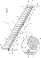
- number 1 denotes as a whole a terminal for road crash barriers, which is preferably adapted to be anchored to the ground at the end of a road crash barrier 100, and is structured so as to reduce damage to things and injury to persons in the event of impact of a vehicle travelling in a direction d substantially parallel to the road crash barrier 100, towards the end of said road crash barrier 100.
- the road crash barrier 100 is furthermore a programmed-deformation road crash barrier.
- the road crash barrier 100 preferably comprises: a series of supporting posts 101, which are advantageously made of metallic material and are driven into the ground in a substantially vertical position, spaced side-by-side along the lateral edge of the roadway; and a series of ribbon-like cross beams 102 preferably with double or triple wave profile, which are advantageously made of metallic material and are securely fixed to the supporting posts 101 in a substantially horizontal position one after the other, at a predetermined height from the ground.
- the ribbon-like cross beams 102 are preferably butt-fixed to one another so as to form a longitudinal metal band, which extends along the lateral edge of the roadway at a predetermined height from the ground, advantageously substantially without interruption.
- the road crash barrier 100 may have a different structure and/or be made at least partly of concrete, wood, polymeric material, composite material and/or other materials.
- the terminal 1 is preferably adapted to form an extension of the road crash barrier 100, and is therefore adapted to be firmly anchored to the ground P along the lateral edge of the roadway.
- the terminal 1 is furthermore structured so as to deform during impact of the vehicle, absorbing at least a part of the kinetic energy of the latter.
- the terminal 1 is preferably also structured so as to prevent, during the impact, parts of the road crash barrier 100 from accidentally penetrating into the vehicle and/or so as to keep the vehicle on the roadway in the event of impact.
- the terminal 1 comprises: a preferably substantially straight, longitudinal member 2 that extends more or less horizontally resting on the ground P, advantageously along the lateral edge of the roadway so as to form an extension of the road crash barrier 100, and is firmly anchored to the ground P; an interconnecting upright 3, which is integral with and rises above the longitudinal member 2 preferably in a substantially vertical direction, and is adapted to be rigidly fixed to the free end of the road crash barrier 100; and a row of programmed-deformation modules with oblong tubular structure, separate and distinct from one another, which are arranged side-by-side and securely anchored to one another, and are located in a roughly vertical position above the longitudinal member 2, starting from the interconnecting vertical upright 3 and preferably substantially for the entire length of the longitudinal member 2, so as to form a deformable fence 4 laterally integral with the interconnecting vertical upright 3.
- the single programmed-deformation modules with oblong tubular structure have a monolithic structure.
- the interconnecting vertical upright 3 is preferably located at the proximal end of the longitudinal member 2, and preferably serves as an anchoring point for the free end of the last cross beam 102 of the road crash barrier 100.
- the interconnecting vertical upright 3 furthermore, is preferably separate and distinct from the longitudinal member 2, and is preferably rigidly fixed to the longitudinal member 2.
- the interconnecting vertical upright 3 is preferably arranged astride the vertical mid-plane M of the longitudinal member 2.
- the deformable fence 4 of programmed-deformation modules includes a plurality of first programmed-deformation modules 5 with oblong tubular structure, which are arranged each with its own lower end/mouth slidingly resting on the longitudinal member 2.
- the programmed-deformation modules 5 are therefore separate and distinct from the longitudinal member 2.
- programmed-deformation modules 5 are preferably also arranged astride the vertical mid-plane M of the longitudinal member 2.
- At least a part of the deformable fence 4 is substantially coplanar to the longitudinal member 2, i.e. it lies on the vertical mid-plane of the longitudinal member 2.
- the first programmed-deformation module 5 of the deformable fence 4 is arranged closely juxtaposed and securely anchored to the interconnecting vertical upright 3.
- the programmed-deformation modules 5 furthermore have a monolithic structure.
- the deformable fence 4 formed of the programmed-deformation modules preferably also includes one or more second programmed-deformation modules 6 with oblong tubular structure, which are suspended above the longitudinal member 2, at a predetermined distance from the longitudinal member 2.
- the programmed-deformation modules 6 are therefore separate and distinct from the longitudinal member 2.
- the programmed-deformation modules 6 furthermore have a monolithic structure.
- the deformable fence 4 preferably has a proximal section and a distal section, advantageously adjoined and complementary to each other.
- the proximal section of deformable fence 4 is adjoined and integral with the interconnecting vertical upright 3, and it preferably includes a plurality of programmed-deformation modules 5 having the lower end/mouth slidingly resting on the longitudinal member 2.
- the proximal section of deformable fence 4 is moreover substantially coplanar with the longitudinal member 2.
- the programmed-deformation modules 5 that make up the proximal section of deformable fence 4 preferably lie on the vertical mid-plane M of the longitudinal member 2.
- the distal section of deformable fence 4 is advantageously adjoined and integral with the proximal section, and is preferably made up of one or more programmed-deformation modules 6 consecutive to one another.
- the programmed-deformation modules 6 that make up the distal section of deformable fence 4 are furthermore suspended roughly above the distal end of the longitudinal member 2.
- the distal section of deformable fence 4 is furthermore bent/curved outwards from the roadway.
- At least a part of the programmed-deformation modules 6 forming the distal section of deformable fence 4 is preferably horizontally offset from the vertical mid-plane M of the longitudinal member 2, and the lateral deviation from the vertical mid-plane M increases as the distance of the various programmed-deformation modules 6 from the interconnecting vertical upright 3 increases.
- the terminal 1 is moreover provided with at least one and more conveniently a plurality of protruding contrast members 7, which extend cantilevered from the longitudinal member 2 and engage the lower ends/mouths of at least a part of the programmed-deformation modules 5, so as to thwart/restrain the sliding of the lower ends/mouths of the various programmed-deformation modules 5 along the longitudinal member 2.
- each contrast member 7 is vertically aligned to a respective programmed-deformation module 5, and extends cantilevered from the longitudinal member 2 so as to protrude into the lower end/mouth of said programmed-deformation module 5.
- the protruding contrast members 7 are furthermore appropriately spaced/distributed along the longitudinal member 2.
- the protruding contrast members 7 are preferably spaced/distributed along a segment of the longitudinal member 2 adjacent to and facing the interconnecting vertical upright 3.
- the protruding contrast members 7 are preferably spaced in a substantially regular manner along the longitudinal member 2, or rather along the segment of the longitudinal member 2 located immediately beneath the proximal section of the deformable fence 4.
- the spacing between the contrast members 7 may also progressively decrease as the distance from the interconnecting vertical upright 3 decreases.
- the terminal 1 comprises also a longitudinal cable 8, which has a first end securely fixed on the interconnecting vertical upright 3 at a predetermined height from the ground, extends in a pass-through manner through at least a part of the programmed-deformation modules 5, and lastly has the second end rigidly fixed to the longitudinal member 2 advantageously in proximity of the free end of the deformable fence 4.
- the longitudinal cable 8 is furthermore tensioned so as to press one or more programmed-deformation modules 5 against the longitudinal member 2, and advantageously also lies on the vertical mid-plane M of the longitudinal member substantially for its entire length.
- the longitudinal cable 8 is adapted to oppose any possible misalignment, twisting and/or detachment of the deformable fence 4 from the longitudinal member 2 beneath.
- the longitudinal member 2 is preferably made of metallic material, and preferably has a length greater than 1 m (metre).
- the longitudinal member 2 moreover has a substantially U- or C-shaped profile.
- the longitudinal member 2 may be tubular in shape preferably with rectangular or polygonal section.
- the longitudinal member 2 preferably also has a modular structure.
- the longitudinal member 2 has a nominal length preferably ranging from 2 to 6 m (metres), and preferably comprises two or more straight metal section-bars 10 that preferably have a substantially C-shaped profile and are butt-fixed to one another in a rigid manner, advantageously via a series of connecting bolts.
- the longitudinal member 2 may include one single straight metal section-bar 10.
- the longitudinal member 2 is moreover also provided with at least one substantially U-shaped, supporting bracket 11, which is adapted to embrace a programmed-deformation module 5 from opposite sides thereof, so as to maintain said programmed-deformation module 5 astride the mid-plane M of the longitudinal member 2.
- the supporting bracket 11 preferably has a ribbon-like structure, is preferably made of metallic material, and is preferably arranged above the straight metal section-bar 10, transversally to the longitudinal axis of the latter.
- the supporting bracket 11 is furthermore rigidly fixed to the straight metal section-bar 10 immediately beneath via one or more connecting bolts.
- the longitudinal member 2 is furthermore rigidly anchored to the ground P by means of a pair of anchoring posts, advantageously located at the two ends of said longitudinal member 2.
- the terminal for road crash barriers 1 preferably also comprises: a first anchoring post 12, separate and distinct from the longitudinal member 2 and advantageously made of metallic material, which is driven into the ground at the proximal end of the longitudinal member 2, and is rigidly fixed to said proximal end of the longitudinal member 2 advantageously by means of one or more connecting bolts; and a second anchoring post 13, separate and distinct from the longitudinal member 2 and advantageously made of metallic material, which is driven into the ground at the distal end of the longitudinal member 2 and is rigidly fixed to the same distal end of the longitudinal member 2 advantageously by means of one or more connecting bolts.
- the two anchoring posts 12 and 13 preferably consist of as many straight metal section-bars with U-section.
- At least the distal end of the longitudinal member 2 may be securely anchored to the ground P by means of anchor bolts or other mechanical anchoring members.
- the interconnecting vertical upright 3 is preferably substantially straight and preferably has a nominal height ranging between 0,5 to 1,5 m (metres).
- the interconnecting vertical upright 3 is furthermore made of metallic material.
- the interconnecting vertical upright 3 preferably includes the anchoring post 12, or rather the section/segment of anchoring post 12 that protrudes cantilevered from the ground P and rises upwards advantageously in a substantially vertical direction, to a predetermined height from the ground P.
- the interconnecting vertical upright 3 preferably includes an anchoring post separate and distinct from the longitudinal member 2, which is partially driven into the ground P advantageously in a substantially vertical position and advantageously at the proximal end of the longitudinal member 2, and is rigidly fixed to the longitudinal member 2 advantageously by means of one or more connecting bolts, so as to fix the longitudinal member 2 firmly to the ground P.
- the interconnecting vertical upright 3 preferably comprises: the section/segment of the anchoring post 12 that protrudes cantilevered upwards beyond the longitudinal member 2, or rather beyond the proximal end of the longitudinal member 2; and an outer casing or shell 14 with rigid oblong structure, separate and distinct from the anchoring post 12, which is preferably made of metallic material, and is fitted and/or fixed securely on the anchoring post 12, at least partially covering the latter.
- the outer casing 14 is preferably substantially straight, and is preferably dimensioned so as to cover the anchoring post 12, or rather the segment of the anchoring post 12 protruding from the ground P, substantially for the entire height thereof.
- the first programmed-deformation module 5 of deformable fence 4 is preferably rigidly fixed directly to the side of the interconnecting vertical upright 3, or rather to the side of anchoring post 12 and/or of outer casing or shell 14, by means of a series of connecting bolts.
- the outer casing 14 preferably consists of a ribbon-like straight section bar with substantially U- or C-shaped profile, which advantageously has its two longitudinal edges folded inwards, and is arranged in a substantially vertical position, astride the anchoring post 12, so as to embrace said post from both sides.
- outer casing or shell 14 is therefore arranged astride the vertical mid-plane M of longitudinal member 2.
- the ribbon-like straight section-bar forming the outer casing 14 is preferably made of metallic material, and is preferably rigidly fixed to the anchoring post 12 by means of a series of connecting bolts advantageously located on both sides of the anchoring post 12.
- the ribbon-like straight section-bar forming the outer casing 14 finally also has a nominal length preferably greater than or equal to the length of the segment of the anchoring post 12 that protrudes cantilevered from the ground P.
- the programmed-deformation modules 5 and 6 of deformable fence 4 are separate and independent from each other, and are preferably rigidly fixed to each other by means of connecting bolts.
- the programmed-deformation modules 5 and 6 are preferably substantially straight and are preferably substantially perpendicular to the longitudinal member 2.
- the programmed-deformation modules 5 and/or 6 are furthermore made of metallic material.
- each programmed-deformation module 5, 6 is preferably substantially prismatic in shape, and is preferably fixed to the immediately adjacent programmed-deformation modules 5, 6 at two opposite flat faces of the prism.
- each programmed-deformation module 5 of the deformable fence 4 preferably has a straight tubular structure with roughly octagonal section.
- at least one and more conveniently each programmed-deformation module 6 of the deformable fence 4 preferably has a straight tubular structure with roughly octagonal section.
- the programmed-deformation modules 5 and/or 6 may also have a straight tubular structure with substantially rectangular or hexagonal section.
- one or more of the programmed-deformation modules 5 and/or 6 is/are made of press-folded sheet metal.
- each programmed deformation module 5 and/or 6 is preferably formed of a ribbon-like metal sheet of suitable thickness, which is bent substantially in the shape of a C so as to form a substantially tubular structure.
- each programmed-deformation module 5 is preferably formed of a ribbon-like metal sheet 15 of suitable thickness, which is substantially C-bent along eight bending lines parallel to its longitudinal axis, so as to form a substantially tubular structure.
- the ribbon-like metal sheet 15 is furthermore substantially C-bent so as to arrange the two longitudinal edges/flaps of the ribbon-like metal sheet 15 one side-by-side and substantially coplanar to the other.
- the two longitudinal edges/flaps of the ribbon-like metal sheet 15 are preferably spaced from each other, so as to form/delimit a longitudinal slit, which extends along the side of the programmed-deformation module 5 substantially for the entire length of the programmed-deformation module 5, and is advantageously also arranged astride the mid-plane of the programmed-deformation module 5.
- each programmed deformation module 6 is preferably formed of a ribbon-like metal sheet of suitable thickness, which is substantially C-bent along eight bending lines parallel to its longitudinal axis, so as to form a substantially tubular structure and, preferably, also so as to arrange the two longitudinal edges/flaps of said ribbon-like metal sheet one side-by-side and substantially coplanar to the other.
- the two longitudinal edges/flaps of the ribbon-like metal sheet are furthermore spaced from each other, so as to form/delimit a longitudinal slit that extends along the side of the programmed-deformation module 6, substantially for the entire length of the programmed-deformation module 6, and is advantageously also arranged astride the mid-plane of the programmed-deformation module 6.
- the programmed-deformation modules 5 and/or 6 may lack the longitudinal slit.
- At least a part of the programmed-deformation modules 5 moreover have their lower end/mouth arranged astride the longitudinal member 2.
- the lower end/mouth of these programmed-deformation modules 5 is substantially U-shaped, so as to straddle and embrace the longitudinal member 2 on opposite sides thereof.
- At least a part of the programmed-deformation modules 5 preferably have, on the rim of their lower end/mouth, at least one coupling notch, or more conveniently a pair of reciprocally opposed coupling notches, which is/are preferably located astride the mid-plane of the programmed-deformation module 5, and is/are shaped so as to be engaged in free slidable manner by the longitudinal member 2.
- the coupling notch(es) present on the rim of the lower end/mouth of the programmed-deformation module 5 allow said end/mouth to be arranged astride the longitudinal member 2.
- the coupling notch(es) present on the rim of the lower end/mouth of the programmed-deformation module 5 preferably has/have a shape substantially complementary to that of the longitudinal member 2.
- the proximal section of deformable fence 4 is preferably divided into two consecutive sectors complementary to each other.
- the first sector is adjoined and integral with the interconnecting vertical upright 3, and is preferably formed of a plurality of programmed deformation modules 5, which are provided with said coupling notches on the rim of their lower end/mouth, and are arranged with their lower end/mouth astride the longitudinal member 2.
- the second sector preferably borders the distal section of deformable fence 4 and is preferably formed of a plurality of programmed-deformation modules 5, which simply rest on the upper side of the longitudinal member 2, namely they lack said coupling notches on the rim of their lower end/mouth.
- the ribbon-like metal sheet 15 with C-shaped profile that forms each programmed-deformation module 5 with the lower end/mouth astride the longitudinal member 2 preferably has, on the edge that contributes to forming the lower end/mouth of the tubular structure, an advantageously substantially U-shaped, recess 16 which is arranged on the opposite side relative to the longitudinal slit 17 laterally delimited by the two longitudinal edges/flaps of said ribbon-like metal sheet 15.
- the recess 16 furthermore has a shape complementary to that of the longitudinal member 2.
- the width of longitudinal slit 17, on the other hand, is slightly greater than the width of the longitudinal member 2, or rather the width of the straight section-bar 10, so as to allow the longitudinal member 2 to also engage the longitudinal slit 17 and thus be able to cross the programmed-deformation module 5 from one side to the other.
- the recess 16 and the longitudinal slit 17 preferably form the coupling notches of the programmed-deformation module 5.
- the contrast members 7 extend cantilevered from the longitudinal member 2 so as to protrude with clearance into the lower ends/mouths of the programmed-deformation modules 5 above.
- contrast members 7 extend cantilevered from the longitudinal member 2 preferably so as to protrude into the lower ends/mouths of only the programmed-deformation modules 5 that are arranged astride the longitudinal member 2.
- protruding contrast members 7 are preferably also arranged on the longitudinal member 2 so as to remain spaced from the lateral walls of the corresponding programmed-deformation modules 5 until the impact of the vehicle.
- the protruding contrast members 7 are furthermore arranged in pairs on opposite sides of the vertical mid-plane M of longitudinal member 2, advantageously in a substantially specular position relative to the vertical mid-plane M.
- the contrast members 7 preferably consist of rigid bodies advantageously made of metallic material, which are securely fixed along the two lateral sides of the longitudinal member 2, or rather along the two lateral sides of the straight metal section-bar 10, so as to form teeth or shoulders that protrude from the longitudinal member 2 more or less orthogonally to the latter.
- protruding contrast members 7, or rather the rigid bodies may also be fixed/arranged on the upper side of the longitudinal member 2, advantageously astride the vertical mid-plane M of the longitudinal member 2.
- each contrast member 7 preferably consists of a small block of metallic material advantageously substantially parallelepipedal in shape, which is rigidly fixed on the side of the longitudinal member 2 advantageously via welding.
- the block of metallic material may be rigidly fixed to the side of longitudinal member 2 also by means of one or more connecting bolts.
- the longitudinal cable 8 preferably has a multi-strand structure and is preferably made of metallic material.
- the longitudinal cable 8 preferably has a substantially horizontal starting segment, which extends more or less parallel to the longitudinal member 2 and crosses the programmed-deformation modules 5 of the proximal section of deformable fence 4, engaging pass-through openings 18 made in each programmed-deformation module 5, advantageously astride the mid-plane of the programmed-deformation module 5; and a descending final segment, which extends obliquely underneath the programmed-deformation modules 6 of the distal section of deformable fence 4, and ends on the longitudinal member 2.
- the first end of longitudinal cable 8 is moreover firmly fixed to the interconnecting vertical upright 3 by the interposition of a screw tensioning device 20 or similar.
- the second end of longitudinal cable 8 is preferably rigidly connected directly to the distal end of the longitudinal member 2.
- the programmed-deformation modules 6 of the distal section of deformable fence 4 and the programmed-deformation modules 5 of the proximal section of deformable fence 4 are squashed/ deform, while absorbing at least a part of the kinetic energy of the vehicle.
- the contrast members 7 located along the longitudinal member 2 increase the rigidity to squashing of the programmed-deformation modules 5 nearest to the interconnecting vertical upright 3, thus increasing the amount of energy necessary for the plastic deformation thereof.
- the presence of the protruding contrast members 7 along the longitudinal member 2 allows the absorption capacity of the kinetic energy of the vehicle to be significantly increased.
- contrast members 7, furthermore, allows to reduce, at equal performances, the thickness of all or some of the programmed-deformation modules that form the deformable fence 4, thus reducing the overall weight of the structure and, therefore, the production costs of the terminal 1.
- the protruding contrast members 7, or rather the projecting rigid bodies may be arranged on the longitudinal member 2 so as to remain permanently in abutment on a lateral wall of the corresponding programmed-deformation module 5.
- the pass-through openings 18 on the programmed-deformation modules 5 may be arranged at different heights from the longitudinal member 2 so that the starting segment of the longitudinal cable 8 extends above the longitudinal member 2 following a zigzag path.
- This expedient increases the friction in the contact points between the longitudinal cable 8 and the various programmed-deformation modules 5, thus increasing the capacity of the terminal 1 to absorb the kinetic energy of the vehicle in the event of an impact.
- clamps 21 that are shaped/ dimensioned so that they cannot pass through the pass-through openings 18 on the programmed-deformation modules 5.
- the clamps 21 lodge on the walls of the programmed-deformation modules 5 and oppose the squashing of the latter, thus increasing the capacity of the terminal 1 to absorb the kinetic energy of the vehicle in the event of impact.
- one or more programmed-deformation modules 5 are also provided with transversal braces 22 preferably made of metallic material and preferably with ribbon-like structure, which extend bridge-like between two opposite lateral walls of the programmed-deformation module 5, more or less perpendicular to the vertical mid-plane M of longitudinal member 2, so as to be stretched during squashing of the programmed-deformation module 5.
- the deformable fence 4 may lack the distal section.
Landscapes
- Engineering & Computer Science (AREA)
- Architecture (AREA)
- Civil Engineering (AREA)
- Structural Engineering (AREA)
- Refuge Islands, Traffic Blockers, Or Guard Fence (AREA)
Applications Claiming Priority (1)
| Application Number | Priority Date | Filing Date | Title |
|---|---|---|---|
| IT202200015372 | 2022-07-21 |
Publications (1)
| Publication Number | Publication Date |
|---|---|
| EP4310254A1 true EP4310254A1 (de) | 2024-01-24 |
Family
ID=83506326
Family Applications (1)
| Application Number | Title | Priority Date | Filing Date |
|---|---|---|---|
| EP23186671.6A Pending EP4310254A1 (de) | 2022-07-21 | 2023-07-20 | Endelement für strassenleitplanken |
Country Status (3)
| Country | Link |
|---|---|
| EP (1) | EP4310254A1 (de) |
| BR (1) | BR102023014764A2 (de) |
| IL (1) | IL304579A (de) |
Cited By (3)
| Publication number | Priority date | Publication date | Assignee | Title |
|---|---|---|---|---|
| GB2637526A (en) * | 2024-01-25 | 2025-07-30 | Hill & Smith Infrastructure Ltd | Terminal for a road barrier |
| RU2856646C1 (ru) * | 2025-09-03 | 2026-02-24 | Открытое Акционерное Общество "Завод Продмаш" | Дорожное фронтальное ограждение |
| EP4729695A1 (de) * | 2024-10-15 | 2026-04-22 | voestalpine Krems Finaltechnik GmbH | Anpralldämpfer oder terminal |
Families Citing this family (1)
| Publication number | Priority date | Publication date | Assignee | Title |
|---|---|---|---|---|
| WO2023178342A1 (en) * | 2022-03-18 | 2023-09-21 | Hill & Smith Inc. | Crash attenuator assemblies for decelerating vehicles |
Citations (4)
| Publication number | Priority date | Publication date | Assignee | Title |
|---|---|---|---|---|
| DE20317174U1 (de) * | 2003-11-04 | 2004-04-08 | Sps Schutzplanken Gmbh | Anpralldämpfer an Verkehrswegen |
| DE202005006224U1 (de) * | 2005-04-18 | 2006-03-02 | Sps Schutzplanken Gmbh | Anpralldämpfer zum Einsatz vor Hindernissen an Verkehrswegen |
| KR20140096768A (ko) * | 2013-01-29 | 2014-08-06 | 강승구 | 차량 충돌 충격 흡수장치 |
| WO2016087448A1 (en) | 2014-12-01 | 2016-06-09 | Obex Systems Ltd. | Terminal for road crash barrier |
-
2023
- 2023-07-19 IL IL304579A patent/IL304579A/en unknown
- 2023-07-20 EP EP23186671.6A patent/EP4310254A1/de active Pending
- 2023-07-21 BR BR102023014764-0A patent/BR102023014764A2/pt unknown
Patent Citations (4)
| Publication number | Priority date | Publication date | Assignee | Title |
|---|---|---|---|---|
| DE20317174U1 (de) * | 2003-11-04 | 2004-04-08 | Sps Schutzplanken Gmbh | Anpralldämpfer an Verkehrswegen |
| DE202005006224U1 (de) * | 2005-04-18 | 2006-03-02 | Sps Schutzplanken Gmbh | Anpralldämpfer zum Einsatz vor Hindernissen an Verkehrswegen |
| KR20140096768A (ko) * | 2013-01-29 | 2014-08-06 | 강승구 | 차량 충돌 충격 흡수장치 |
| WO2016087448A1 (en) | 2014-12-01 | 2016-06-09 | Obex Systems Ltd. | Terminal for road crash barrier |
Cited By (5)
| Publication number | Priority date | Publication date | Assignee | Title |
|---|---|---|---|---|
| GB2637526A (en) * | 2024-01-25 | 2025-07-30 | Hill & Smith Infrastructure Ltd | Terminal for a road barrier |
| WO2025158140A1 (en) * | 2024-01-25 | 2025-07-31 | Hill & Smith Infrastructure Ltd | Terminal for a road barrier |
| EP4729695A1 (de) * | 2024-10-15 | 2026-04-22 | voestalpine Krems Finaltechnik GmbH | Anpralldämpfer oder terminal |
| WO2026082820A1 (de) * | 2024-10-15 | 2026-04-23 | Voestalpine Krems Finaltechnik Gmbh | Anpralldämpfer oder terminal für ein fahrzeugrückhaltesystem oder für ein hindernis |
| RU2856646C1 (ru) * | 2025-09-03 | 2026-02-24 | Открытое Акционерное Общество "Завод Продмаш" | Дорожное фронтальное ограждение |
Also Published As
| Publication number | Publication date |
|---|---|
| BR102023014764A2 (pt) | 2024-01-30 |
| IL304579A (en) | 2024-02-01 |
Similar Documents
| Publication | Publication Date | Title |
|---|---|---|
| EP4310254A1 (de) | Endelement für strassenleitplanken | |
| US6719483B1 (en) | Collision safety device | |
| US20080283807A1 (en) | Safety Barrier Anchorage | |
| EP0924347A1 (de) | Sicherheitsendanlage für Leitplanken | |
| RU2003758C1 (ru) | Тросовое дорожное ограждение | |
| US20080247820A1 (en) | Cable-Release Anchor Assembly | |
| AU2006269700A1 (en) | Cable barrier system | |
| WO2013039806A1 (en) | Cable guardrail safety system | |
| WO2010079334A1 (en) | Road safety fences and posts therefor | |
| US3502303A (en) | Fencing | |
| AU2018278981A1 (en) | High tension cable barrier for roadways | |
| US7604221B2 (en) | Guardrail run | |
| GB2450352A (en) | Wire rope vehicle restraining fence | |
| GB2433285A (en) | Vehicle restraining fence for a building | |
| EP1382748B1 (de) | Leitplankenendbereich | |
| US7258326B2 (en) | Wall made of bagel split tires | |
| RU2856646C1 (ru) | Дорожное фронтальное ограждение | |
| JP3680208B2 (ja) | ロープの間隔保持装置 | |
| KR200228307Y1 (ko) | 가드레일 | |
| EP2110479B1 (de) | Übergangsanordnung für Leitplanken | |
| AU2017100422A4 (en) | High tension cable barrier for roadways | |
| IT202300024426A1 (it) | Barriera stradale con protezione per motociclisti | |
| NZ730107A (en) | High tension cable barrier for roadways |
Legal Events
| Date | Code | Title | Description |
|---|---|---|---|
| PUAI | Public reference made under article 153(3) epc to a published international application that has entered the european phase |
Free format text: ORIGINAL CODE: 0009012 |
|
| STAA | Information on the status of an ep patent application or granted ep patent |
Free format text: STATUS: THE APPLICATION HAS BEEN PUBLISHED |
|
| AK | Designated contracting states |
Kind code of ref document: A1 Designated state(s): AL AT BE BG CH CY CZ DE DK EE ES FI FR GB GR HR HU IE IS IT LI LT LU LV MC ME MK MT NL NO PL PT RO RS SE SI SK SM TR |
|
| STAA | Information on the status of an ep patent application or granted ep patent |
Free format text: STATUS: REQUEST FOR EXAMINATION WAS MADE |
|
| 17P | Request for examination filed |
Effective date: 20240723 |
|
| RBV | Designated contracting states (corrected) |
Designated state(s): AL AT BE BG CH CY CZ DE DK EE ES FI FR GB GR HR HU IE IS IT LI LT LU LV MC ME MK MT NL NO PL PT RO RS SE SI SK SM TR |