EP4310281A2 - Verrouillage de porte de panneau - Google Patents
Verrouillage de porte de panneau Download PDFInfo
- Publication number
- EP4310281A2 EP4310281A2 EP23214506.0A EP23214506A EP4310281A2 EP 4310281 A2 EP4310281 A2 EP 4310281A2 EP 23214506 A EP23214506 A EP 23214506A EP 4310281 A2 EP4310281 A2 EP 4310281A2
- Authority
- EP
- European Patent Office
- Prior art keywords
- line
- pair
- housing
- mounting portion
- lockout device
- Prior art date
- Legal status (The legal status is an assumption and is not a legal conclusion. Google has not performed a legal analysis and makes no representation as to the accuracy of the status listed.)
- Pending
Links
Images




Classifications
-
- E—FIXED CONSTRUCTIONS
- E05—LOCKS; KEYS; WINDOW OR DOOR FITTINGS; SAFES
- E05B—LOCKS; ACCESSORIES THEREFOR; HANDCUFFS
- E05B55/00—Locks in which a sliding latch is used also as a locking bolt
- E05B55/005—Cylindrical or tubular locks
-
- E—FIXED CONSTRUCTIONS
- E05—LOCKS; KEYS; WINDOW OR DOOR FITTINGS; SAFES
- E05C—BOLTS OR FASTENING DEVICES FOR WINGS, SPECIALLY FOR DOORS OR WINDOWS
- E05C19/00—Other devices specially designed for securing wings, e.g. with suction cups
- E05C19/18—Portable devices specially adapted for securing wings
- E05C19/186—Portable devices specially adapted for securing wings with a pair of hooks, which are movable towards each other for grasping of an element on the wing, respectively on the frame, or for grasping of an element on each of the wings forming a double door
-
- E—FIXED CONSTRUCTIONS
- E05—LOCKS; KEYS; WINDOW OR DOOR FITTINGS; SAFES
- E05B—LOCKS; ACCESSORIES THEREFOR; HANDCUFFS
- E05B19/00—Keys; Accessories therefor
- E05B19/0017—Key profiles
- E05B19/0035—Key profiles characterized by longitudinal bit variations
-
- E—FIXED CONSTRUCTIONS
- E05—LOCKS; KEYS; WINDOW OR DOOR FITTINGS; SAFES
- E05B—LOCKS; ACCESSORIES THEREFOR; HANDCUFFS
- E05B63/00—Locks or fastenings with special structural characteristics
- E05B63/18—Locks or fastenings with special structural characteristics with arrangements independent of the locking mechanism for retaining the bolt or latch in the retracted position
- E05B63/20—Locks or fastenings with special structural characteristics with arrangements independent of the locking mechanism for retaining the bolt or latch in the retracted position released automatically when the wing is closed
-
- E—FIXED CONSTRUCTIONS
- E05—LOCKS; KEYS; WINDOW OR DOOR FITTINGS; SAFES
- E05B—LOCKS; ACCESSORIES THEREFOR; HANDCUFFS
- E05B67/00—Padlocks; Details thereof
- E05B67/38—Auxiliary or protective devices
- E05B67/383—Staples or the like for padlocks; Lock slings; Arrangements on locks to cooperate with padlocks
-
- E—FIXED CONSTRUCTIONS
- E05—LOCKS; KEYS; WINDOW OR DOOR FITTINGS; SAFES
- E05C—BOLTS OR FASTENING DEVICES FOR WINGS, SPECIALLY FOR DOORS OR WINDOWS
- E05C19/00—Other devices specially designed for securing wings, e.g. with suction cups
- E05C19/18—Portable devices specially adapted for securing wings
- E05C19/188—Removably mounted securing devices, e.g. devices clamped to the wing or the frame
-
- E—FIXED CONSTRUCTIONS
- E05—LOCKS; KEYS; WINDOW OR DOOR FITTINGS; SAFES
- E05C—BOLTS OR FASTENING DEVICES FOR WINGS, SPECIALLY FOR DOORS OR WINDOWS
- E05C19/00—Other devices specially designed for securing wings, e.g. with suction cups
- E05C19/003—Locking bars, cross bars, security bars
-
- E—FIXED CONSTRUCTIONS
- E05—LOCKS; KEYS; WINDOW OR DOOR FITTINGS; SAFES
- E05Y—INDEXING SCHEME ASSOCIATED WITH SUBCLASSES E05D AND E05F, RELATING TO CONSTRUCTION ELEMENTS, ELECTRIC CONTROL, POWER SUPPLY, POWER SIGNAL OR TRANSMISSION, USER INTERFACES, MOUNTING OR COUPLING, DETAILS, ACCESSORIES, AUXILIARY OPERATIONS NOT OTHERWISE PROVIDED FOR, APPLICATION THEREOF
- E05Y2900/00—Application of doors, windows, wings or fittings thereof
- E05Y2900/10—Application of doors, windows, wings or fittings thereof for buildings or parts thereof
- E05Y2900/13—Type of wing
- E05Y2900/132—Doors
Definitions
- This application relates to a lockout device for panel doors such as, for example, doors on breaker boxes that may have various circuit breakers contained therein.
- Electrical breaker boxes can contain multiple circuit breaker switches inside of them. Such boxes typically have a cover or front panel that is opened to provide access to number of circuit breakers. In addition to automatically tripping to protect an electrical circuit from being damaged by excess current from an overloaded or shorted circuit, these circuit breakers may be manually turned off, for example, if electrical work is being performed or equipment is being serviced.
- the aforementioned panel door locks are not always well suited for lockout type applications and/or are not easy to install, remove, transport, and store.
- many of the locking devices that exist are multi-component and limited in the manner in which they can be used. Such multi-component devices may be awkward to install, as two components or more components may need to be held in place while an additional point needs to be manipulated or engaged to secure them together. Moreover, when such devices are multi-component with separable components, one of the components may be easy to misplace or separated from the others, rendering the device useless.
- locking devices are designed to span a length of more than a foot in many cases, these devices, especially when rigid, can be large and cumbersome to carry and/or store. Likewise, if rigid, a particular locking device may only be suitable for use with a narrow range of panel widths and limited in its range of application.
- an improved lockout device for a door on a panel.
- This device incorporates an openable/closeable housing and a flexible line extending therethrough. Both the housing and one end of the flexible line can be mountable to the front panel at edges or fasteners so the device traverses a door on the panel and potentially restricts that door from being opened when the lockout device is secured.
- the line With the housing opened, the line can be drawn taut (potentially temporarily secured in place with the housing still opened, for example, by the engagement of cleated cams with the line).
- the line Upon closing the housing, the line can be secured in position using one or more line engagement elements such as clamping teeth that are engaged with the flexible line by the act of closure of the housing.
- One or more locks can be attached to the closed housing to retain the housing in the closed and line-secured position as part of a group-compatible lockout process and only after all locks are removed may the housing be opened and the flexible line released from its position such that the lockout device can be removed from the panel.
- the flexible line permits the device to be smaller and more compact once removed to accommodate easy storage, especially compared to a fully rigid device.
- the line can be provided with features on its axial ends and interact with the housing in such a way that the housing and line cannot be separated from one another - meaning that neither of the components is likely to be lost.
- multiple openings can be readily provided so that the housing can be secured in the closed position as part of a group lockout process (in comparison to some known designs in which only a single lock may be used to secure the device in the secured position, or there is not a sufficient way to ensure the lockout is maintained, even if multiple locks were used.
- a lockout device for a door on a panel.
- the lockout device includes a housing and a flexible line.
- the housing has a first mounting portion adapted for securement to one side of the panel and the flexible line has on one end thereof a second mounting portion adapted for securement to another side of the panel from the first mounting portion.
- the housing further supports at least one line engagement element and the flexible line extends through at least a portion of the housing including the line engagement element(s) for selective engagement therewith.
- the flexible line when the first mounting portion and the second mounting portion are secured to opposite sides of the panel, the flexible line may be drawn taut across the door and may be secured with the line engagement element(s) so as to inhibit removal of the lockout device from the panel and prevent an opening of the door.
- the housing may have a pair of movable sections (movable in that at least one of the sections is movable with respect to the other section), at least one of the pair of movable sections may support line engagement element(s), and the pair of movable sections may be movable with respect to one another between an open position in which the line engagement element(s) is/are accessible and a closed position in which the pair of movable sections are lockable together such that the line engagement element(s) is/are not accessible.
- one of the pair of movable sections may include a tab with lock openings and the other of the pair of movable section may include a slot through which the tab may pass.
- a lock may be placed in one of the lock openings to prevent the separation of the pair of movable sections from one another and to restrict access to the line engagement element(s).
- the pair of movable sections may be hinged together on one side thereof and may be moveable between the open position and the closed position in a clamshell fashion.
- each of the pair of movable sections may have clamping teeth as at least a part of the line engagement element(s) and, when the pair of movable sections are closed together, the clamping teeth can engage the flexible line to grip the flexible line at the clamping teeth. It is contemplated that the clamping teeth may be molded as part of the pair of movable sections.
- the line engagement element(s) may include a pair of cleated cams between which the flexible line is receivable.
- a guide for the line may connect the pair of cleated cams on a top end thereof may be used to provide a restricted space apart from (but adjacent to) the pair of cleated cams for the disengagement of the flexible line from the pair of cleated cams while retaining the flexible line in the housing.
- the line engagement element(s) may include clamping teeth.
- the line engagement elements may include clamping teeth between which teeth the flexible line extends and may further include a pair of cleated cams between which the flexible line is positionable.
- the pair of cleated cams may accommodate a temporary or initial positioning of the flexible line during installation of the lockout device onto a box while the housing is still opened and, when the pair of movable sections are brought together, the clamping teeth may further engage and secure the flexible line.
- the line engagement element(s) may include or further include housing openings on the housing that close around the flexible line as the housing is closed.
- first mounting portion and the second mounting portion may include brackets that are adapted to be wrapped around an edge of the panel.
- first mounting portion and the second mounting portion additionally or alternatively to the brackets on one or both portions, the first mounting portion and the second mounting portion include many openings or notches which are adapted to be secured via a corresponding fastener to the panel.
- first mounting portion and the second mounting portion may each include brackets that are adapted to be wrapped around an edge of the panel and may further include openings or notches which are adapted to be secured via a fastener to the panel. Those openings and notches could be separate from the brackets or potentially made a part of them depending on the geometry and design.
- the flexible line may have a stop at the end of the flexible line not having the second mounting portion.
- the housing may include one or more line openings, guides, or loops through which the flexible line extends and the stop and the second mounting portion can be sized relative to line openings, guides, or loops to inhibit the passage of the stop and the second mounting portion past the line openings, guides, or loops.
- the housing and the flexible line may not be completely separable from one another once assembled together.
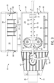
- a lockout device 10 is illustrated in an opened and a closed position, respectively.
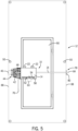
- This lockout device 10 is designed for attachment to the front panel of a box with a door such as a breaker box 12 as is shown, for example, in FIGS. 5 , 6A , 6B , 7A, and 7B .
- the lockout device 10 includes two main parts.
- the first of these parts is a housing 14 and the second of these parts is a flexible line 16.
- the housing 14 may be made for example from a relatively rigid component, such as a plastic or metal, while the flexible line 16 may be made for example from a fibrous string or cable or even potentially a polymeric or woven cable that is flexible about its axial length (as well as being sufficiently compliant or deformable locally so that the line 16 is capable of being engaged by the later-described line engagement elements for positional securement). It is further desirable that the line 16 that it not be easily cut or easily damaged under the moderately low amounts of tension it may come under during use or under the engagement with the line engagement elements as will be described in greater detail below.
- the housing 14 has a pair of movable sections 18 and 20 that are connected to one another in a clamshell or book-like fashion at hinges 22.
- the sections 18 and 20 are "movable" in that at least one of the section is to movable relative to the other.
- the hinges 22 are pin-less, having arcuate projections that extend from one of the movable sections 18 and 20 into a receiving loop on the other of the movable section 18 and 20.
- one of each of these projections and loops are provided on each one of the movable sections 18 and 20 and are arranged so that they can only be potentially separated from one another in one or some of the angular positions of the opened positions.
- each of the movable sections 18 and 20 provides a generally concave and hollow volume 24, 26 defined by a base wall 28, 30 with a set of peripheral side walls 32, 34, respectively.
- the edges 36, 38 of the peripheral side walls 32, 34 meet to create a largely-enclosed cavity 40 from the two volumes 32, 34 as best seen in the cross-sectional view of FIG. 4 .
- movable sections 18 and 20 There are various other features found in or supported by the movable sections 18 and 20. These features generally relate to one of [1] mounting the housing 14 on the front panel of the box 12 (using an edge thereof or a fastener received therein), [2] locking the movable sections 18 and 20 in the closed position, and/or [3] securing the position of the flexible line 16 in the housing 14 when the movable sections 18 and 20 of the housing 14 are closed during use.
- the leftmost side of the housing 14 has a flange 42 projecting therefrom that provides a first mounting portion 44.
- This first mounting portion 44 is on the one of the movable sections that is to be received closest to the front face of the panel (as illustrated, this is movable section 18). In this way, it can be ensured that the other one of the movable sections (as illustrated, movable section 20) can be opened and closed relative to movable section that is directly mounted and may be immobile relative to the box 12 at that point.
- the section closest to the front panel shall be the section that supports the first mounting portion 44.
- the first mounting portion 44 includes structure for two different modes of mounting.
- the first mode of mounting is a U-shaped bracket 46 which may be wrapped around an edge 88 of panel during mounting of the lockout device 10, for example, as is illustrated in FIGS. 5 and 6A .
- This bracket 46 may be hinged or movable relative to the housing 14 and/or the flange 42, as is illustrated in FIG. 7A , so that the bracket 46 may not project laterally outward to the left when other mounting means (described more below) are employed.
- the view of FIG. 7A is perhaps the best view to show the U-shaped portion of the bracket 46, which is at least partially obstructed in the other views, and how it can hinge or pivot.
- the first mounting portion 44 also offers a second mode of mounting which involves a key slot shaped mounting opening 48 for reception of a fastener or screw 50 therethrough in which the fastener or screw 50 can be secured to the panel of the box 12 as is shown, for example, in FIG. 7A . It is contemplated that the fastener or screw 50 may already be a part of the box 12 and its assembly or may be added thereto for mounting purposes specifically.
- the use of the key slot shape can permit the head of a screw or fastener 50 to pass through the larger part of the opening 48 and then the housing 14 moved (e.g., rightward as illustrated) such that the stem of the fastener 50 enters the slender portion of the opening 48 from which the mounting portion 44 cannot be lifted from the panel surface due to the engagement of the area surrounding the slot with the larger head of the fastener or screw 50.
- the housing 14 also includes a locking mechanism 52 that can, when the movable sections 18 and 20 are in the closed position of FIG. 2 , be used to secure the movable sections 18 and 20 together.
- the locking mechanism 52 includes, as a first part thereof, a tab 54 projecting forwardly from the base wall 28 of the movable section 18 in which the tab 54 has a set of lock openings 56 at a distal end thereof.
- the locking mechanism 52 further includes a slot 58 in the base wall 30 of the movable section 20.
- the tab 54 is received into and extends through the slot 58. Accordingly, in this closed position, the distal-most portion of the tab 54 from the base wall 28 extends outside of the cavity 40, such that the lock openings 56 are available and accessible outside the cavity 40 as shown in FIG. 2 .
- a shackle of a padlock 60 can be run through one of these openings 56, to prevent the closed housing 14 from being re-opened until the padlock 60 is removed as the base wall 30 of the movable section 20 is blocked from moving past the opening(s) 56 when the opening(s) 56 are occupied by the shackle(s) of the padlock(s) 60.
- each of the movable sections may have a plurality of openings on a projecting tab or wall and, when the sections are brought together, the sets of openings on each of the sections may be aligned with one another to permit securement in that closed position by one or more locks.
- the housing 14 has and supports various structures or line engagement elements that can be used to secure or grip the flexible line 16 that runs right to left through the housing 14 as best shown in FIG. 3 .
- These line engagement elements include, in the form illustrated, three different line engagement elements including clamping teeth 62 on the inside of the cavity 40, a pair of cleated cams 64, and undersized housing openings 66.
- a set of clamping teeth 62 are molded into or supported by the base walls 28 and 30. These teeth 62 are linearly positioned along the path of the flexible line 16 between the housing openings 66 through the cavity 40 of the housing 14 such that, when the housing 14 is closed in clamshell fashion, the clamping teeth 62 close towards one another and engage the flexible line 16 on opposing sides to engage and slightly dig into the flexible line 16 as best shown in FIG. 4 .
- the clamping teeth 62 are separated, such that the flexible line 16 is free of the clamping teeth 62 and the line 16 can slide over the bottom set of the teeth 62 on section 18 without being held by them.
- the undersized housing openings 66 can likewise pinch the flexible line 16 at the locations where the flexible line 16 enters and exits the housing 14.
- These undersized housing openings 66 are formed at the left and right sides of the peripheral side walls 32, 34 (for example, as half-circle shapes which, as illustrated, includes one section as part of a recess and one section on a projection 68 extending out from the edge 38 of the wall 34), so that part of the openings 66 are formed each on the edge 36, 38 of each opposing side walls 32, 34.
- the two movable sections 18 and 20 are closed together, these half sections join to form the openings 66 and close around the flexible line 16 to grip the line 16 at these points.
- the openings 66 can taper to a point over their axial length and this taper can be seen, for example, in FIG. 4 to engage or bite into the flexible line 16.
- cleated cams 64 there are also a set of cleated cams 64 within the housing 14 as can be best seen in FIGS. 1 and 3 .
- These cleated cams 64 are rotatably mounted to the base wall 28 of the section 18 (with respective rotational axes that are generally perpendicular to the base wall 28 of the section 18).
- a passageway 70 is provided between the cleated cams 64 that can receive the flexible line 16.
- both of these cleated cams 64 are teardrop shaped with the tips of the cleated cams 64 facing leftward in the orientations illustrated.
- line engagement elements are shown in the illustrated embodiment, that, in other forms, not all of these line engagement elements need be present or they may be used in other combinations with one another or separately.
- one or more of the line engagement elements may be omitted or other types of line engagement elements used in combination with those specifically described.
- line engagement elements other than those depicted here may be used to similar effect, assuming that their use can be restricted by the closure of a housing.
- the line 16 runs from right to left through the housing 14.
- the guides 72 and 74 are found on opposite sides of the clamping teeth 62, with the guide 72 on the rightmost side of the housing 14 arching up from the basewall 28 and potentially being formed integrally therewith by molding or the like.
- the leftmost guide 74 is attached at the ends of the axes of the cleated cams 64.
- This leftmost guide 74 can help with retaining the flexible line 16 near the cleated cams 64, while still permitting the line 16 to be lifted away or forward to manually disengage the line from the cleated cams 64, when desired, without fully separating the two from one another.
- features on the axial ends on the flexible line 16 can prevent the axial separation of the line 16 from the housing 14 by moving the line 16 too far in one direction.
- a stop 76 is attached at the axial end of the line 16.
- the stop 76 is large enough that it cannot travel past the cleated cams 64, the passageway 70 between them, and the guide 74 above the cams 62 if the line 16 is pulled rightward fully.
- This second mounting portion 78 can be an L-shaped bracket 80 with the line 16 running through an opening 82 on one of the walls of the bracket 80 and having a stop 84 that keeps the bracket 80 from sliding off the end of the line 16.
- the other wall of the L-shaped bracket 80 has a notch 86 in it which may be used to accommodate reception of a screw or fastener 50 as will be described in greater detail below when describing FIG. 7B .
- the second mounting portion 78 is also large enough that it cannot pass through the guide 72 if the line 16 is pulled leftward fully.
- the housing 14 and the flexible line 16 can form a single inseparable lockout device or assembly. In this way, the parts can be kept together.
- the lockout device 10 can be stored quite compactly, lacking long rigid elements that are found in some other locks.
- the lockout device 10 is shown attached to a pair of opposing lateral sides or edges 88 of a breaker box 12 so as to secure a door 90 of the front panel in a closed position (so as to for example, limit access to the circuit breakers found therein).
- both the first mounting portion 44 and the second mounting portion 78 are wrapped around the edges 88 as shown in FIGS. 6A and 6B , respectively. This is initially done with the housing 14 in the opened position of FIGS. 1 and 3 such that the flexible line 16 can be drawn taut by pulling the leftmost end of the flexible line 16 leftward.
- the line 16 may be temporarily held in place by inserting the line 16 in the passageway 70 between the cleated cams 64. If the line 16 was already between the cams 64, such placement may be unnecessary and the leftward pulling may effectively just serve to maintain the position as the line 16 is pulled leftward and not permit substantial rightward return of the line.
- the movable section 20 can be closed into section 18 in clamshell fashion to engage the clamping teeth 62 and the housing openings 66 with the line 16 to further hold the line 16 in place with respect to the housing 14.
- the housing 14 may be opened to automatically disengage the line engagement elements of the clamping teeth 62 and the housing openings 66 and the line 16.
- the line 16 may also be manually lifted outward or forwardly to withdraw the line 16 from between the cleated cams 64. With that last line engagement element disengaged, slack can be created within the flexible line 16 that permits the first mounting portion 44 and the second mounting portion 78 to be separated apart from one another and removed from the breaker box 12. In this way, the entire lockout device 10 can also be removed from the box 12.
- FIGS. 5 , 6A, and 6B illustrate the mounting of the device 10 using brackets 46 and 80 wrapped around the edges 88
- other modes of mounting may be used to similar effect.
- FIGS. 7A and 7B it is contemplated that either or both of the previously described edge-bracket mountings from FIGS. 6A and 6B could be replaced with fastener type mountings involving fastener and a keyhole type opening 48 (or other opening) as illustrated in FIG. 7A or involving a fastener 50 and a notch 86 on the bracket 80 as illustrated in FIG. 7B .
- the fastener 50 may be slightly loosened (but not wholly removed) from the box 12 to provide initial clearance between the fastener head and panel face.
- the opening 48 or notch 86 can then be slid into engagement with the loosened fastener 50, such that the fastener 50 serves as an anchoring point to permit the line 16 is drawn taut during the installation process.
- an improved lockout device for securing a panel door is disclosed.
- the device may be kept unitary as a single component and accommodate a wide range of panel widths, but still able to be compactly stored and easily transported due to the flexibility of the line.
- the device is well adapted for group lockout use and links the closing locking action to the securement of the line in the housing. Beyond this, it can be flexible in mode of mounting, accommodating various types of mounting based on the circumstances of use.
Landscapes
- Engineering & Computer Science (AREA)
- Mechanical Engineering (AREA)
- Structural Engineering (AREA)
- Patch Boards (AREA)
- Lock And Its Accessories (AREA)
Applications Claiming Priority (2)
| Application Number | Priority Date | Filing Date | Title |
|---|---|---|---|
| US16/892,041 US11525284B2 (en) | 2020-06-03 | 2020-06-03 | Panel door lockout |
| EP21176009.5A EP3919709B1 (fr) | 2020-06-03 | 2021-05-26 | Verrouillage de porte à panneau |
Related Parent Applications (2)
| Application Number | Title | Priority Date | Filing Date |
|---|---|---|---|
| EP21176009.5A Division-Into EP3919709B1 (fr) | 2020-06-03 | 2021-05-26 | Verrouillage de porte à panneau |
| EP21176009.5A Division EP3919709B1 (fr) | 2020-06-03 | 2021-05-26 | Verrouillage de porte à panneau |
Publications (2)
| Publication Number | Publication Date |
|---|---|
| EP4310281A2 true EP4310281A2 (fr) | 2024-01-24 |
| EP4310281A3 EP4310281A3 (fr) | 2024-04-17 |
Family
ID=76138003
Family Applications (2)
| Application Number | Title | Priority Date | Filing Date |
|---|---|---|---|
| EP21176009.5A Active EP3919709B1 (fr) | 2020-06-03 | 2021-05-26 | Verrouillage de porte à panneau |
| EP23214506.0A Pending EP4310281A3 (fr) | 2020-06-03 | 2021-05-26 | Verrouillage de porte de panneau |
Family Applications Before (1)
| Application Number | Title | Priority Date | Filing Date |
|---|---|---|---|
| EP21176009.5A Active EP3919709B1 (fr) | 2020-06-03 | 2021-05-26 | Verrouillage de porte à panneau |
Country Status (2)
| Country | Link |
|---|---|
| US (2) | US11525284B2 (fr) |
| EP (2) | EP3919709B1 (fr) |
Families Citing this family (5)
| Publication number | Priority date | Publication date | Assignee | Title |
|---|---|---|---|---|
| US11525284B2 (en) * | 2020-06-03 | 2022-12-13 | Brady Worldwide, Inc. | Panel door lockout |
| US12044040B2 (en) * | 2021-04-02 | 2024-07-23 | Brady Worldwide, Inc. | Cable lockout device |
| US12031610B2 (en) | 2021-12-22 | 2024-07-09 | Brady Worldwide, Inc. | Clamping cable lockout |
| US12320163B2 (en) | 2022-06-29 | 2025-06-03 | Brady Worldwide, Inc. | Multicable lockout device |
| AT527223B1 (de) * | 2023-11-09 | 2024-12-15 | Georg Mossbauer | Vorrichtung zur Notverriegelung von Schiebetüren |
Citations (4)
| Publication number | Priority date | Publication date | Assignee | Title |
|---|---|---|---|---|
| US7681421B2 (en) | 2007-06-11 | 2010-03-23 | Richard Michael Cannon | Electrical panel lockout |
| US9184573B1 (en) | 2012-02-28 | 2015-11-10 | Mesquite Fabrication, Inc. | Enclosure locking system |
| US9243431B1 (en) | 2013-09-13 | 2016-01-26 | Daniel DeLeon | Lock-out tag-out bar system |
| US9284760B2 (en) | 2012-02-23 | 2016-03-15 | Adk Electric Corporation | Electrical panelboard guard |
Family Cites Families (29)
| Publication number | Priority date | Publication date | Assignee | Title |
|---|---|---|---|---|
| US3059952A (en) * | 1958-11-05 | 1962-10-23 | Emil A Wittman | Device for preventing car doors from opening |
| US3903719A (en) * | 1974-08-02 | 1975-09-09 | Harold Katz | Bicycle lock assembly |
| GB2137682B (en) * | 1983-02-17 | 1986-05-29 | Laurence North | Security device |
| GB8515087D0 (en) | 1985-06-14 | 1985-07-17 | Paling T A | Security apparatus |
| US4970882A (en) * | 1989-11-22 | 1990-11-20 | Arrendondo Ralph A | Bicycle cable lock |
| US5369970A (en) * | 1993-01-25 | 1994-12-06 | Winner International | Compartment lock |
| US5419165A (en) * | 1993-12-08 | 1995-05-30 | Perkins; Jon T. | Electrical panel locking apparatus |
| US5452929A (en) * | 1994-03-07 | 1995-09-26 | Universal Development Enterprises | Keyless door lock |
| US5466023A (en) * | 1994-05-02 | 1995-11-14 | Williamson; Christopher H. | Security door bar system and method of use |
| US5447346A (en) * | 1994-06-15 | 1995-09-05 | G&D Communications Corporation | Portable, adjustable, telescopic clamping lock for truck sliding windows |
| US5517835A (en) * | 1994-09-09 | 1996-05-21 | Smith; Allen | Cable locking device |
| US5582046A (en) * | 1995-04-25 | 1996-12-10 | Baumwoll; Joel P. | Automotive vehicle access preventive device |
| US5573289A (en) * | 1995-09-01 | 1996-11-12 | Littlefair; Lawrence L. | Entry way security chain |
| US5620215A (en) * | 1995-09-20 | 1997-04-15 | Janeway; Kenneth | Sliding window lock |
| US5722266A (en) * | 1995-11-21 | 1998-03-03 | Alpha Enterprises, Inc. | Universal wrap security device |
| US5823020A (en) * | 1996-05-09 | 1998-10-20 | Brady Usa, Inc. | Cable locking system |
| US5716084A (en) * | 1996-07-31 | 1998-02-10 | Sanford, Jr.; Jack G. | Door security system |
| US5842359A (en) * | 1997-08-06 | 1998-12-01 | Longueira; Christopher F. | Anti-theft auxiliary lock for vehicles |
| CA2242063A1 (fr) | 1998-06-29 | 1999-12-29 | Larry Mabee | Verrouillage de chenilles pour motoneiges |
| US6705652B2 (en) * | 2002-06-25 | 2004-03-16 | Arnold Richard Engel | Security system |
| US9212508B2 (en) * | 2004-09-20 | 2015-12-15 | Stanton Concepts, L.L.C. | Security link |
| US7870767B2 (en) * | 2005-06-13 | 2011-01-18 | Master Lock Company Llc | Lockout device |
| CN101243276B (zh) * | 2005-06-13 | 2011-11-16 | 总锁有限责任公司 | 锁定装置 |
| US7325281B1 (en) * | 2006-07-25 | 2008-02-05 | George Lee Willems | Security strap |
| CA2611641C (fr) * | 2006-12-27 | 2012-09-04 | Dirk Buis | Moyen de fermeture d'une porte pour la maintenir fermee |
| US9105168B2 (en) | 2011-03-09 | 2015-08-11 | Checkpoint Systems, Inc. | Method and apparatus for securing related products |
| US20180106071A1 (en) * | 2016-10-19 | 2018-04-19 | Raymond IVY | Double door safety lock |
| BR202018003573U2 (pt) | 2018-02-23 | 2019-09-10 | 97º LICENCIAMENTOS LTDA EPP | disposição construtiva introduzida em dispositivo de travamento/destravamento de tira lacre temporária |
| US11525284B2 (en) * | 2020-06-03 | 2022-12-13 | Brady Worldwide, Inc. | Panel door lockout |
-
2020
- 2020-06-03 US US16/892,041 patent/US11525284B2/en active Active
-
2021
- 2021-05-26 EP EP21176009.5A patent/EP3919709B1/fr active Active
- 2021-05-26 EP EP23214506.0A patent/EP4310281A3/fr active Pending
-
2022
- 2022-11-14 US US17/986,646 patent/US12252904B2/en active Active
Patent Citations (4)
| Publication number | Priority date | Publication date | Assignee | Title |
|---|---|---|---|---|
| US7681421B2 (en) | 2007-06-11 | 2010-03-23 | Richard Michael Cannon | Electrical panel lockout |
| US9284760B2 (en) | 2012-02-23 | 2016-03-15 | Adk Electric Corporation | Electrical panelboard guard |
| US9184573B1 (en) | 2012-02-28 | 2015-11-10 | Mesquite Fabrication, Inc. | Enclosure locking system |
| US9243431B1 (en) | 2013-09-13 | 2016-01-26 | Daniel DeLeon | Lock-out tag-out bar system |
Also Published As
| Publication number | Publication date |
|---|---|
| US20210381277A1 (en) | 2021-12-09 |
| EP3919709B1 (fr) | 2024-01-17 |
| US11525284B2 (en) | 2022-12-13 |
| EP3919709A1 (fr) | 2021-12-08 |
| US12252904B2 (en) | 2025-03-18 |
| EP3919709C0 (fr) | 2024-01-17 |
| US20230077093A1 (en) | 2023-03-09 |
| EP4310281A3 (fr) | 2024-04-17 |
Similar Documents
| Publication | Publication Date | Title |
|---|---|---|
| US12252904B2 (en) | Panel door lockout | |
| US5788294A (en) | Tamper deterring seal | |
| US6351975B1 (en) | Bolt lock with protective cover | |
| US7204721B2 (en) | Connector | |
| US20040040824A1 (en) | Switch lever lock out assembly | |
| KR101251076B1 (ko) | 사물함 잠금장치 | |
| JP2000341812A (ja) | 引出形回路遮断器の収納箱のインターロック装置 | |
| GB2158662A (en) | Locking means for plug and socket assembly | |
| US6490411B1 (en) | APS loyalty camera with locking film door and external key therefor | |
| KR101958223B1 (ko) | 사물함 도어 개폐장치 | |
| JP2003314128A (ja) | 樹脂製ボックスの構造 | |
| JP4438996B2 (ja) | 装置の筐体構造およびサブカバー開閉構造 | |
| KR101961308B1 (ko) | 배전반용 도어핸들조립체 | |
| KR100621116B1 (ko) | 배선용 차단기의 핸들 록 장치 | |
| CN1156638C (zh) | 手提箱和袋及类似物的关闭组件 | |
| KR101251077B1 (ko) | 사물함 잠금장치 | |
| KR102865498B1 (ko) | 가구용 잠금장치 | |
| CN110661175A (zh) | 配电盘壳体 | |
| JP2004064881A (ja) | 電気接続箱 | |
| KR200147287Y1 (ko) | 셔터의 잠금장치 | |
| JP3408572B2 (ja) | 開閉操作装置 | |
| CA2457572C (fr) | Charniere dissimulee | |
| JP2000248817A (ja) | ヒンジ | |
| EP1875023A1 (fr) | Ensemble logement | |
| BR102022015554B1 (pt) | Sistema de fixação para um sistema de travamento montado e método para montar um sistema de fixação |
Legal Events
| Date | Code | Title | Description |
|---|---|---|---|
| PUAI | Public reference made under article 153(3) epc to a published international application that has entered the european phase |
Free format text: ORIGINAL CODE: 0009012 |
|
| STAA | Information on the status of an ep patent application or granted ep patent |
Free format text: STATUS: THE APPLICATION HAS BEEN PUBLISHED |
|
| AC | Divisional application: reference to earlier application |
Ref document number: 3919709 Country of ref document: EP Kind code of ref document: P |
|
| AK | Designated contracting states |
Kind code of ref document: A2 Designated state(s): AL AT BE BG CH CY CZ DE DK EE ES FI FR GB GR HR HU IE IS IT LI LT LU LV MC MK MT NL NO PL PT RO RS SE SI SK SM TR |
|
| REG | Reference to a national code |
Ref country code: DE Ref legal event code: R079 Free format text: PREVIOUS MAIN CLASS: E05B0067380000 Ipc: E05C0019180000 |
|
| PUAL | Search report despatched |
Free format text: ORIGINAL CODE: 0009013 |
|
| AK | Designated contracting states |
Kind code of ref document: A3 Designated state(s): AL AT BE BG CH CY CZ DE DK EE ES FI FR GB GR HR HU IE IS IT LI LT LU LV MC MK MT NL NO PL PT RO RS SE SI SK SM TR |
|
| RIC1 | Information provided on ipc code assigned before grant |
Ipc: E05B 67/38 20060101ALI20240314BHEP Ipc: E05C 19/18 20060101AFI20240314BHEP |
|
| STAA | Information on the status of an ep patent application or granted ep patent |
Free format text: STATUS: REQUEST FOR EXAMINATION WAS MADE |
|
| 17P | Request for examination filed |
Effective date: 20240930 |
|
| RBV | Designated contracting states (corrected) |
Designated state(s): AL AT BE BG CH CY CZ DE DK EE ES FI FR GB GR HR HU IE IS IT LI LT LU LV MC MK MT NL NO PL PT RO RS SE SI SK SM TR |
|
| GRAP | Despatch of communication of intention to grant a patent |
Free format text: ORIGINAL CODE: EPIDOSNIGR1 |
|
| STAA | Information on the status of an ep patent application or granted ep patent |
Free format text: STATUS: GRANT OF PATENT IS INTENDED |
|
| INTG | Intention to grant announced |
Effective date: 20260312 |