EP4310302A1 - Flugzeugsystem mit durch einen gasturbinenmotor angetriebenem verdichter - Google Patents
Flugzeugsystem mit durch einen gasturbinenmotor angetriebenem verdichter Download PDFInfo
- Publication number
- EP4310302A1 EP4310302A1 EP23187374.6A EP23187374A EP4310302A1 EP 4310302 A1 EP4310302 A1 EP 4310302A1 EP 23187374 A EP23187374 A EP 23187374A EP 4310302 A1 EP4310302 A1 EP 4310302A1
- Authority
- EP
- European Patent Office
- Prior art keywords
- compressor
- rotor
- section
- gearbox
- aircraft system
- Prior art date
- Legal status (The legal status is an assumption and is not a legal conclusion. Google has not performed a legal analysis and makes no representation as to the accuracy of the status listed.)
- Pending
Links
Images




Classifications
-
- F—MECHANICAL ENGINEERING; LIGHTING; HEATING; WEAPONS; BLASTING
- F02—COMBUSTION ENGINES; HOT-GAS OR COMBUSTION-PRODUCT ENGINE PLANTS
- F02C—GAS-TURBINE PLANTS; AIR INTAKES FOR JET-PROPULSION PLANTS; CONTROLLING FUEL SUPPLY IN AIR-BREATHING JET-PROPULSION PLANTS
- F02C7/00—Features, components parts, details or accessories, not provided for in, or of interest apart form groups F02C1/00 - F02C6/00; Air intakes for jet-propulsion plants
- F02C7/36—Power transmission arrangements between the different shafts of the gas turbine plant, or between the gas-turbine plant and the power user
-
- F—MECHANICAL ENGINEERING; LIGHTING; HEATING; WEAPONS; BLASTING
- F02—COMBUSTION ENGINES; HOT-GAS OR COMBUSTION-PRODUCT ENGINE PLANTS
- F02C—GAS-TURBINE PLANTS; AIR INTAKES FOR JET-PROPULSION PLANTS; CONTROLLING FUEL SUPPLY IN AIR-BREATHING JET-PROPULSION PLANTS
- F02C3/00—Gas-turbine plants characterised by the use of combustion products as the working fluid
- F02C3/04—Gas-turbine plants characterised by the use of combustion products as the working fluid having a turbine driving a compressor
- F02C3/06—Gas-turbine plants characterised by the use of combustion products as the working fluid having a turbine driving a compressor the compressor comprising only axial stages
- F02C3/073—Gas-turbine plants characterised by the use of combustion products as the working fluid having a turbine driving a compressor the compressor comprising only axial stages the compressor and turbine stages being concentric
-
- F—MECHANICAL ENGINEERING; LIGHTING; HEATING; WEAPONS; BLASTING
- F02—COMBUSTION ENGINES; HOT-GAS OR COMBUSTION-PRODUCT ENGINE PLANTS
- F02C—GAS-TURBINE PLANTS; AIR INTAKES FOR JET-PROPULSION PLANTS; CONTROLLING FUEL SUPPLY IN AIR-BREATHING JET-PROPULSION PLANTS
- F02C3/00—Gas-turbine plants characterised by the use of combustion products as the working fluid
- F02C3/04—Gas-turbine plants characterised by the use of combustion products as the working fluid having a turbine driving a compressor
- F02C3/10—Gas-turbine plants characterised by the use of combustion products as the working fluid having a turbine driving a compressor with another turbine driving an output shaft but not driving the compressor
-
- F—MECHANICAL ENGINEERING; LIGHTING; HEATING; WEAPONS; BLASTING
- F02—COMBUSTION ENGINES; HOT-GAS OR COMBUSTION-PRODUCT ENGINE PLANTS
- F02C—GAS-TURBINE PLANTS; AIR INTAKES FOR JET-PROPULSION PLANTS; CONTROLLING FUEL SUPPLY IN AIR-BREATHING JET-PROPULSION PLANTS
- F02C3/00—Gas-turbine plants characterised by the use of combustion products as the working fluid
- F02C3/04—Gas-turbine plants characterised by the use of combustion products as the working fluid having a turbine driving a compressor
- F02C3/107—Gas-turbine plants characterised by the use of combustion products as the working fluid having a turbine driving a compressor with two or more rotors connected by power transmission
- F02C3/113—Gas-turbine plants characterised by the use of combustion products as the working fluid having a turbine driving a compressor with two or more rotors connected by power transmission with variable power transmission between rotors
-
- F—MECHANICAL ENGINEERING; LIGHTING; HEATING; WEAPONS; BLASTING
- F02—COMBUSTION ENGINES; HOT-GAS OR COMBUSTION-PRODUCT ENGINE PLANTS
- F02C—GAS-TURBINE PLANTS; AIR INTAKES FOR JET-PROPULSION PLANTS; CONTROLLING FUEL SUPPLY IN AIR-BREATHING JET-PROPULSION PLANTS
- F02C3/00—Gas-turbine plants characterised by the use of combustion products as the working fluid
- F02C3/14—Gas-turbine plants characterised by the use of combustion products as the working fluid characterised by the arrangement of the combustion chamber in the plant
-
- F—MECHANICAL ENGINEERING; LIGHTING; HEATING; WEAPONS; BLASTING
- F02—COMBUSTION ENGINES; HOT-GAS OR COMBUSTION-PRODUCT ENGINE PLANTS
- F02C—GAS-TURBINE PLANTS; AIR INTAKES FOR JET-PROPULSION PLANTS; CONTROLLING FUEL SUPPLY IN AIR-BREATHING JET-PROPULSION PLANTS
- F02C6/00—Plural gas-turbine plants; Combinations of gas-turbine plants with other apparatus; Adaptations of gas-turbine plants for special use
- F02C6/18—Plural gas-turbine plants; Combinations of gas-turbine plants with other apparatus; Adaptations of gas-turbine plants for special use using the waste heat of gas-turbine plants outside the plants themselves, e.g. gas-turbine power heat plants
-
- F—MECHANICAL ENGINEERING; LIGHTING; HEATING; WEAPONS; BLASTING
- F02—COMBUSTION ENGINES; HOT-GAS OR COMBUSTION-PRODUCT ENGINE PLANTS
- F02C—GAS-TURBINE PLANTS; AIR INTAKES FOR JET-PROPULSION PLANTS; CONTROLLING FUEL SUPPLY IN AIR-BREATHING JET-PROPULSION PLANTS
- F02C6/00—Plural gas-turbine plants; Combinations of gas-turbine plants with other apparatus; Adaptations of gas-turbine plants for special use
- F02C6/20—Adaptations of gas-turbine plants for driving vehicles
- F02C6/206—Adaptations of gas-turbine plants for driving vehicles the vehicles being airscrew driven
-
- F—MECHANICAL ENGINEERING; LIGHTING; HEATING; WEAPONS; BLASTING
- F02—COMBUSTION ENGINES; HOT-GAS OR COMBUSTION-PRODUCT ENGINE PLANTS
- F02C—GAS-TURBINE PLANTS; AIR INTAKES FOR JET-PROPULSION PLANTS; CONTROLLING FUEL SUPPLY IN AIR-BREATHING JET-PROPULSION PLANTS
- F02C7/00—Features, components parts, details or accessories, not provided for in, or of interest apart form groups F02C1/00 - F02C6/00; Air intakes for jet-propulsion plants
- F02C7/32—Arrangement, mounting, or driving, of auxiliaries
-
- F—MECHANICAL ENGINEERING; LIGHTING; HEATING; WEAPONS; BLASTING
- F02—COMBUSTION ENGINES; HOT-GAS OR COMBUSTION-PRODUCT ENGINE PLANTS
- F02K—JET-PROPULSION PLANTS
- F02K3/00—Plants including a gas turbine driving a compressor or a ducted fan
- F02K3/02—Plants including a gas turbine driving a compressor or a ducted fan in which part of the working fluid by-passes the turbine and combustion chamber
- F02K3/04—Plants including a gas turbine driving a compressor or a ducted fan in which part of the working fluid by-passes the turbine and combustion chamber the plant including ducted fans, i.e. fans with high volume, low pressure outputs, for augmenting the jet thrust, e.g. of double-flow type
- F02K3/06—Plants including a gas turbine driving a compressor or a ducted fan in which part of the working fluid by-passes the turbine and combustion chamber the plant including ducted fans, i.e. fans with high volume, low pressure outputs, for augmenting the jet thrust, e.g. of double-flow type with front fan
-
- F—MECHANICAL ENGINEERING; LIGHTING; HEATING; WEAPONS; BLASTING
- F05—INDEXING SCHEMES RELATING TO ENGINES OR PUMPS IN VARIOUS SUBCLASSES OF CLASSES F01-F04
- F05D—INDEXING SCHEME FOR ASPECTS RELATING TO NON-POSITIVE-DISPLACEMENT MACHINES OR ENGINES, GAS-TURBINES OR JET-PROPULSION PLANTS
- F05D2220/00—Application
- F05D2220/30—Application in turbines
- F05D2220/32—Application in turbines in gas turbines
- F05D2220/323—Application in turbines in gas turbines for aircraft propulsion, e.g. jet engines
-
- F—MECHANICAL ENGINEERING; LIGHTING; HEATING; WEAPONS; BLASTING
- F05—INDEXING SCHEMES RELATING TO ENGINES OR PUMPS IN VARIOUS SUBCLASSES OF CLASSES F01-F04
- F05D—INDEXING SCHEME FOR ASPECTS RELATING TO NON-POSITIVE-DISPLACEMENT MACHINES OR ENGINES, GAS-TURBINES OR JET-PROPULSION PLANTS
- F05D2220/00—Application
- F05D2220/50—Application for auxiliary power units (APU's)
Definitions
- This invention relates generally to an aircraft and, more particularly, to a powerplant for the aircraft.
- an aircraft system includes a gas turbine engine, a gearbox and at least one compressor.
- the gas turbine engine includes a compressor section, a turbine section, a combustor section and a rotating structure.
- the combustor section is fluidly coupled with and between the compressor section and the turbine section.
- the rotating structure includes a compressor section rotor within the compressor section and a turbine section rotor within the turbine section.
- the at least one compressor includes a compressor rotor rotatably driven by the rotating structure through the gearbox.
- the gas turbine engine may be dedicated to powering the at least one compressor.
- another aircraft system includes a gas turbine engine, a gearbox, a first compressor and a second compressor.
- the gas turbine engine includes a compressor section, a turbine section, a combustor section and a rotating structure.
- the combustor section is fluidly coupled with and between the compressor section and the turbine section.
- the rotating structure includes a compressor section rotor within the compressor section and a turbine section rotor within the turbine section.
- the first compressor includes a first compressor rotor rotatably driven by the rotating structure through the gearbox.
- the second compressor includes a second compressor rotor rotatably driven by the rotating structure through the gearbox.
- another aircraft system includes a gas turbine engine, a gearbox, a compressor and a fluid circuit.
- the gas turbine engine includes a compressor section, a combustor section, a turbine section, a rotating structure and an engine flowpath.
- the rotating structure includes a compressor section rotor within the compressor section and a turbine section rotor within the turbine section.
- the engine flowpath extends sequentially through the compressor section, the combustor section and the turbine section.
- the compressor includes a compressor rotor rotatably driven by the rotating structure through the gearbox.
- the fluid circuit includes a heat exchanger arranged with the engine flowpath downstream of the turbine section.
- the aircraft system may also include a driven rotor outside of the gas turbine engine and the compressor.
- the driven rotor may be rotatably driven by the rotating structure through the gearbox.
- the gas turbine engine may not power an electric generator.
- the gearbox may be configured as a constant speed transmission between the rotating structure and the compressor rotor.
- the gearbox may be configured as a variable speed transmission between the rotating structure and the compressor rotor.
- An engine flowpath may extend sequentially through the compressor section, the combustor section and the turbine section.
- a compressor flowpath may extend through the at least one compressor.
- the compressor flowpath may be discrete from the engine flowpath.
- the aircraft system may also include a driven rotor rotatably driven by the rotating structure through the gearbox.
- the driven rotor may be rotatably driven by the rotating structure through the gearbox independent of the compressor rotor.
- the compressor rotor may be rotatably driven by the rotating structure through the gearbox independent of the driven rotor.
- the driven rotor may be configured as or otherwise include a propulsor rotor.
- the aircraft system may also include an electric generator which includes the driven rotor.
- the aircraft system may also include a second compressor.
- the second compressor may include a second compressor rotor rotatably driven by the rotating structure through the gearbox.
- the second compressor rotor may be rotatably driven by the rotating structure through the gearbox independent of the compressor rotor.
- the compressor rotor may be rotatably driven by the rotating structure through the gearbox independent of the second compressor rotor.
- an engine flowpath may extend sequentially through the compressor section, the combustor section and the turbine section.
- a compressor flowpath may extend through the compressor and may be discrete from the engine flowpath.
- the second compressor flowpath may extend through the second compressor and may be discrete from the engine flowpath.
- the aircraft system may also include a heat recovery circuit including a first heat exchanger, a turbine expander, a second heat exchanger and a recovery circuit compressor.
- the first heat exchanger may be arranged downstream of the turbine section.
- the aircraft system may also include a driven rotor rotatably driven by a rotor of the turbine expander.
- the aircraft system may also include a fuel circuit including a fuel source, a heat exchanger and a fuel injector.
- the heat exchanger may be arranged downstream of the turbine section.
- the heat exchanger may be fluidly coupled between the fuel source and the fuel injector.
- the fuel injector may be arranged within the combustor section.
- the aircraft system may also include a heat exchanger including a first heat exchanger path and a second heat exchanger path.
- the first heat exchanger path may be fluidly coupled between the compressor section and the combustor section.
- the second heat exchange path may be fluidly coupled with and downstream of the turbine section.
- gas turbine engine and/or the at least one compressor may be configured for operation throughout aircraft flight.
- the gas turbine engine and the at least one compressor may be configured to receive air from discrete (e.g., separate and distinct) inlets.
- the invention may include any one or more of the individual features disclosed above and/or below alone or in any combination thereof.
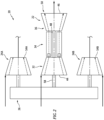
- FIG. 1 illustrates a system 20 for an aircraft.
- This aircraft may be an airplane, a helicopter, a drone (e.g., an unmanned aerial vehicle (UAV)), a spacecraft or any other manned or unmanned aerial vehicle.
- the aircraft system 20 of FIG. 1 includes a gas turbine engine 22, an external compressor 24 and a gearbox 26.
- the term "external” may describe a component separate from, outside of and/or otherwise discrete from the gas turbine engine 22.
- the aircraft system 20 of FIG. 1 also includes one or more fluid components 28 and/or one or more nozzles 30.
- the gas turbine engine 22 of FIG. 1 includes at least (or only) a compressor section 32, a combustor section 34, a turbine section 36 and an (e.g., annular) internal engine flowpath 38.
- the engine flowpath 38 extends from an upstream airflow inlet 40 into the gas turbine engine 22, sequentially through the compressor section 32, the combustor section 34 and the turbine section 36, to a combustion products exhaust 42 from the gas turbine engine 22.
- the combustor section 34 and the turbine section 36 each include a respective bladed rotor 44 and 46.
- Each of these bladed rotors 44, 46 includes a plurality of rotor blades distributed circumferentially around and connected to one or more respective rotor disks and/or hubs.
- the rotor blades may be formed integral with or mechanically fastened, welded, brazed, adhered and/or otherwise attached to the respective rotor disk(s) and/or hub(s).
- the compressor section rotor 44 is connected to the turbine section rotor 46 through an engine shaft 48.
- the compressor section rotor 44, the turbine section rotor 46 and the engine shaft 48 collectively form or are otherwise included in an internal rotating structure 50 of the gas turbine engine 22.
- This rotating structure 50 and its elements 44, 46 and 48 are rotatable about an engine rotational axis 52, which engine rotational axis 52 may also be an axial centerline of the gas turbine engine 22.
- the external compressor 24 may be configured as or otherwise include an axial flow compressor, a (e.g., one piece rotor assembly) centrifugal flow compressor or a combination of an axial flow and a centrifugal flow compressor.
- This external compressor 24 may be a single stage compressor or a multi-stage compressor.
- the external compressor 24 of FIG. 1 includes a bladed compressor rotor 54 rotatable about a compressor rotational axis 56, which compressor rotational axis 56 may also be an axial centerline of the external compressor 24.
- the compressor rotational axis 56 may be parallel with, but laterally offset from / laterally spaced from, the engine rotational axis 52.
- the compressor rotational axis 56 may alternatively be angularly offset from the engine rotational axis 52 by an angle greater than zero degrees (0°) and less than one-hundred and eighty degrees (180°).
- the compressor rotor 54 includes a plurality of compressor blades distributed circumferentially around and connected to one or more respective disks and/or hubs.
- the compressor blades may be formed integral with or mechanically fastened, welded, brazed, adhered and/or otherwise attached to the respective disk(s) and/or hub(s).
- the gearbox 26 operatively couples the rotating structure 50 to the compressor rotor 54.
- the gearbox 26 of FIG. 1 for example, includes a gearbox input 58 (e.g., a shaft, a gear, a coupling, etc.) and a gearbox output 60 (e.g., a shaft, a gear, a coupling, etc.).
- the gearbox input 58 is coupled to and rotatable with the rotating structure 50.
- the gearbox output 60 is coupled to and rotatable with the compressor rotor 54.
- the gearbox output 60 is also coupled to the gearbox input 58 through an internal power transmission system 61 within the gearbox 26; e.g., a gear system, etc.
- the gearbox 26 may be configured as a constant speed transmission. With such a configuration, a ratio between an input speed into the gearbox 26 (e.g., a rotational speed of the gearbox input 58, a rotational speed of the rotating structure 50) and an output speed from the gearbox 26 (e.g., a rotational speed of the gearbox output 60, a rotational speed of the compressor rotor 54) remains constant.
- the gearbox 26, however, may alternatively be configured as a variable speed transmission. With such a configuration, the ratio between the gearbox input speed and the gearbox output speed may change; e.g., selectively go up or down.
- air enters the gas turbine engine 22 and its engine flowpath 38 through the airflow inlet 40.
- This air is compressed by the compressor section rotor 44 and directed into a (e.g., annular) combustion chamber 62 of a combustor 64 in the combustor section 34.
- Fuel is injected into the combustion chamber 62 by one or more fuel injectors 66, and the fuel is mixed with the compressed air to provide a fuel-air mixture.
- the fuel-air mixture is ignited and combustion products thereof flow through and cause the turbine section rotor 46 to rotate.
- the rotation of the turbine section rotor 46 drives rotation of the compressor section rotor 44 and, thus, compression of the air received from the airflow inlet 40.
- the rotation of the turbine section rotor 46 and, more generally, rotation of the rotating structure 50 also drives rotation of the compressor rotor 54 through the gearbox 26.
- the rotation of the compressor rotor 54 compresses (e.g., outside, ambient) air entering the external compressor 24 through an inlet 68 into the external compressor 24. This compressed air is directed out of the external compressor 24 through an outlet 70 from the external compressor 24 and provided to the fluid component(s) 28 to facilitate operation of the fluid component(s) 28.
- the fluid component(s) 28 include, but are not limited to, downstream flow device(s), fluid control device(s), flow conversion component(s) or nozzle(s) configured for providing thrust and/or aerodynamic aircraft controls, aircraft surface(s) and aircraft wing(s).
- the external compressor 24 is disposed outside of the gas turbine engine 22 and its engine flowpath 38. Moreover, a compressor flowpath 72 through the external compressor 24 from the compressor inlet 68 to the compressor outlet 70 is discrete (e.g., fluidly decoupled from, parallel with, etc.) the engine flowpath 38.
- the compressed air discharged from the external compressor 24 and provided to the fluid component(s) 28 and/or the nozzle(s) 30 may thereby be relatively cool, compared to the combustion products discharged from the gas turbine engine 22.
- the external compressor 24 and its compressor rotor 54 may be specifically tailored for (e.g., optimally) providing the compressed air to the fluid component(s) 28 and/or the nozzle(s) 30, whereas the compressor section 32 and its compressor section rotor 44 may be specifically tailored for (e.g., optimally) providing the compressed air to the combustor section 34 for combustion.
- the external compressor 24 and the compressor section 32 of the aircraft system 20 may thereby be more efficient than a single compressor providing compressed air to both a combustion section of a gas turbine engine and other components outside of that gas turbine engine.
- the aircraft system 20 may include a single external compressor 24 coupled to the gas turbine engine 22 through the gearbox 26.
- the external compressor 24 may be one of a plurality of external compressors 24 (e.g., 24A and 24B) coupled to the gas turbine engine 22 through the gearbox 26. These external compressors 24 may have a common configuration. Alternatively, at least one of the external compressors 24 may be configured (e.g., sized, etc.) different than another one of the external compressors 24.
- the external compressors 24A and 24B may be individually coupled to the gas turbine engine 22 via the gearbox 26.
- the compressor rotor 54A may be rotatably driven by the rotating structure 50 through the gearbox 26 independent of the compressor rotor 54B.
- the compressor rotor 54B may be rotatably driven by the rotating structure 50 through the gearbox 26 independent of the compressor rotor 54A.
- the present disclosure is not limited to such an exemplary parallel arrangement.
- the gas turbine engine 22 may be dedicated to powering the external compressor(s) 24.
- the gas turbine engine 22, for example, may not be configured to power any other aircraft components (e.g., propulsor, generator, etc.) and/or provide (e.g., significant or any) aircraft thrust.
- the combustion products exhausted from the gas turbine engine 22 may be utilized to provide aircraft thrust; e.g., the gas turbine engine 22 may be a turbojet gas turbine engine 22.
- the gas turbine engine 22 and its rotating structure 50 may be configured to drive rotation of at least (or only) one additional component through the gearbox 26.
- the second gearbox output 60 is coupled to and rotatable with a driven rotor 74 within an electric generator 76.
- the second gearbox output 60 is coupled to and rotatable with a driven rotor of an aircraft propulsor; e.g., a bladed propulsor rotor 78.
- the propulsor rotor 78 may be configured as or otherwise include an open propulsor rotor such as, but not limited to, a propeller or a helicopter rotor (e.g., a main rotor).
- the propulsor rotor 78 may alternatively be configured as or otherwise include a ducted propulsor rotor such as, but not limited to, a fan rotor.
- the compressor rotor 54 of FIGS. 3 and 4 may be rotatably driven by the rotating structure 50 through the gearbox 26 independent of the driven rotor 74, 78.
- the driven rotor 74, 78 of FIGS. 3 and 4 may be rotatably driven by the rotating structure 50 through the gearbox 26 independent of the compressor rotor 54.
- the present disclosure is not limited to such an exemplary parallel arrangement.
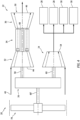
- the gas turbine engine 22 may be configured with a heat recovery circuit 80.
- This heat recovery circuit 80 of FIG. 5 includes a first heat exchanger 82, a turbine expander 84 (also referred to as a turboexpander), a second heat exchanger 86 and a recovery circuit compressor 88.
- the first heat exchanger 82 is arranged with the engine flowpath 38 downstream of the turbine section 36.
- the first heat exchanger 82 includes an inlet 90 fluidly coupled with and downstream of an outlet 92 from the recovery circuit compressor 88.
- the first heat exchanger 82 also includes an outlet 94 fluidly coupled with and upstream of an inlet 96 to the turbine expander 84.
- the turbine expander 84 includes its inlet 96 and an outlet 98 fluidly coupled with and upstream of an inlet 100 to the second heat exchanger 86.
- the turbine expander 84 also includes a bladed turbine expander rotor 102 configured to drive rotation of a driven rotor 104 of a mechanical load 106.
- This mechanical load 106 may be an electric generator, a bladed propulsor rotor or another device.
- the second heat exchanger 86 includes its inlet 100 and an outlet 108 fluidly coupled with and upstream of an inlet 110 to the recovery circuit compressor 88.
- the recovery circuit compressor 88 includes its outlet 92, its inlet 110 and a bladed compressor rotor 112, where the compressor rotor 112 may be coupled to and rotatably driven by the turbine expander rotor 102 (or another device).
- fluid e.g., refrigerant
- fluid e.g., refrigerant
- This pressurized fluid absorbs heat energy from the combustion products exhausted from the turbine section 36 through the first heat exchanger 82.
- the heated and pressurized fluid flows through the turbine expander 84 and drives rotation of the turbine expander rotor 102.
- the fluid output from the turbine expander 84 is condensed by the second heat exchanger 86 before flowing into the recovery circuit compressor 88.
- the rotation of the turbine expander rotor 102 may drive rotation of the compressor rotor 112 and/or the driven rotor 104.
- the heat recovery circuit 80 may thereby capture waste heat energy exhausted with the combustion products from the gas turbine engine 22 and use that captured energy to power the mechanical load 106.
- the gas turbine engine 22 may be configured with a fuel circuit 114.
- This fuel circuit 114 includes a fuel source 116 (e.g., a fuel reservoir and/or a fuel pump), a heat exchanger 118 and the fuel injector(s) 66.
- the heat exchanger 118 is arranged with the engine flowpath 38 downstream of the turbine section 36.
- the heat exchanger 118 includes an inlet 120 fluidly coupled with and downstream of an outlet 122 from the fuel source 116.
- the heat exchanger 118 also includes an outlet 124 fluidly coupled with and upstream of inlet(s) 126 to the fuel injector(s) 66. With this arrangement, the heat exchanger 118 may pre-heat the fuel provided to the fuel injector(s) 66 to facilitate more efficient combustion.
- the gas turbine engine 22 may be configured with a heat exchanger 128 such as a recuperator / an intercooler.
- the heat exchanger 128 of FIG. 7 includes a first heat exchanger path 130 and a second heat exchanger path 132.
- the first heat exchanger path 130 is fluidly coupled with and between the compressor section 32 and the combustor section 34.
- the first heat exchanger path 130 may thereby form a select portion of the engine flowpath 38 between the compressor section 32 and the combustor section 34.
- the second heat exchanger path 132 is fluidly coupled with and between the turbine section 36 and the combustion products exhaust 42.
- the second heat exchanger path 132 may thereby form a select portion of the engine flowpath 38 between the turbine section 36 and combustion products exhaust 42. With this arrangement, the heat exchanger 128 may pre-heat the compressed air provided to the combustor section 34 to facilitate more efficient combustion.
- the gas turbine engine 22 and the external compressor(s) 24 may be operated through aircraft operation; e.g., during taxiing, takeoff, climb, cruise, descent and/or landing. Such continuous operation is in contrast to, for example, intermittent operation of a typical auxiliary power unit (APU). However, in other embodiments, the gas turbine engine 22 and/or the external compressor(s) may be selectively operated.
- aircraft operation e.g., during taxiing, takeoff, climb, cruise, descent and/or landing.
- Such continuous operation is in contrast to, for example, intermittent operation of a typical auxiliary power unit (APU).
- APU auxiliary power unit
- the gas turbine engine 22 and/or the external compressor(s) may be selectively operated.
- the aircraft system 20 may include various gas turbine engines other than the one described above.
- the aircraft system 20, for example, may include a geared turbine engine or a direct drive gas turbine engine.
- the gas turbine engine may include a single spool (e.g., rotating structure) or multiple spools (e.g., rotating structures).
- the turbine engine may be configured as a turbofan engine, a turbojet engine, a turboprop engine, a turboshaft engine, a propfan engine, a pusher fan engine or any other type of turbine engine.
- the gas turbine engine may also be configured as a hybrid engine with, for example, one or more electric machines (e.g., electric motors) for selectively driving rotation of the compressor rotor(s) 54 through the gearbox 26.
- the present disclosure therefore is not limited to any particular types or configurations of gas turbine engines.
Landscapes
- Engineering & Computer Science (AREA)
- Chemical & Material Sciences (AREA)
- Combustion & Propulsion (AREA)
- Mechanical Engineering (AREA)
- General Engineering & Computer Science (AREA)
- Structures Of Non-Positive Displacement Pumps (AREA)
Applications Claiming Priority (2)
| Application Number | Priority Date | Filing Date | Title |
|---|---|---|---|
| US202263391470P | 2022-07-22 | 2022-07-22 | |
| US18/091,860 US12215628B2 (en) | 2022-07-22 | 2022-12-30 | Aircraft system with gas turbine engine powered compressor |
Publications (1)
| Publication Number | Publication Date |
|---|---|
| EP4310302A1 true EP4310302A1 (de) | 2024-01-24 |
Family
ID=87473918
Family Applications (1)
| Application Number | Title | Priority Date | Filing Date |
|---|---|---|---|
| EP23187374.6A Pending EP4310302A1 (de) | 2022-07-22 | 2023-07-24 | Flugzeugsystem mit durch einen gasturbinenmotor angetriebenem verdichter |
Country Status (2)
| Country | Link |
|---|---|
| US (1) | US12215628B2 (de) |
| EP (1) | EP4310302A1 (de) |
Citations (5)
| Publication number | Priority date | Publication date | Assignee | Title |
|---|---|---|---|---|
| US20130097992A1 (en) * | 2011-10-21 | 2013-04-25 | Gabriel L. Suciu | Integrated thermal management system and environmental control system for a gas turbine engine |
| US20140084677A1 (en) * | 2011-05-20 | 2014-03-27 | Turbomeca | Method for rationalising a chain of electrical components of an aircraft, implementation architecture and corresponding aircraft |
| US20160332736A1 (en) * | 2014-01-31 | 2016-11-17 | Safran Aircraft Engines | Supply of air to an air-conditioning circuit of an aircraft cabin from its turboprop engine |
| US20170284408A1 (en) * | 2016-03-14 | 2017-10-05 | Safran Aircraft Engines | Supply of air to an air-conditioning circuit of an aircraft cabin |
| US20220018262A1 (en) * | 2016-08-11 | 2022-01-20 | General Electric Company | Mechanically driven air vehicle thermal management device |
Family Cites Families (10)
| Publication number | Priority date | Publication date | Assignee | Title |
|---|---|---|---|---|
| GB905534A (en) * | 1960-07-27 | 1962-09-12 | Rolls Royce | Improvements in or relating to gas turbine engines |
| GB1212875A (en) * | 1967-12-21 | 1970-11-18 | Rolls Royce | Aircraft |
| US4900231A (en) * | 1986-05-30 | 1990-02-13 | The Boeing Company | Auxiliary compressor air supply for an aircraft |
| JP2543314Y2 (ja) * | 1990-09-26 | 1997-08-06 | 日本精工株式会社 | トロイダル型無段変速機 |
| US20160069264A1 (en) * | 2013-07-22 | 2016-03-10 | Joseph D. Brostmeyer | Gas turbine engine with turbine cooling and combustor air preheating |
| US20180162537A1 (en) * | 2016-12-09 | 2018-06-14 | United Technologies Corporation | Environmental control system air circuit |
| US11519337B2 (en) | 2019-06-24 | 2022-12-06 | Pratt & Whitney Canada Corp. | Gas turbine auxiliary power unit |
| US11390386B2 (en) * | 2019-08-27 | 2022-07-19 | Pratt & Whitney Canada Corp. | System and method for increasing bleed air flow to a heat exchanger with a fluid-driven fluid propeller |
| US12110828B2 (en) | 2020-10-28 | 2024-10-08 | Kawasaki Jukogyo Kabushiki Kaisha | Gas turbine engine for use in aircraft |
| US12196137B2 (en) * | 2021-06-11 | 2025-01-14 | Rtx Corporation | Gas turbine engine with electrically driven compressor |
-
2022
- 2022-12-30 US US18/091,860 patent/US12215628B2/en active Active
-
2023
- 2023-07-24 EP EP23187374.6A patent/EP4310302A1/de active Pending
Patent Citations (5)
| Publication number | Priority date | Publication date | Assignee | Title |
|---|---|---|---|---|
| US20140084677A1 (en) * | 2011-05-20 | 2014-03-27 | Turbomeca | Method for rationalising a chain of electrical components of an aircraft, implementation architecture and corresponding aircraft |
| US20130097992A1 (en) * | 2011-10-21 | 2013-04-25 | Gabriel L. Suciu | Integrated thermal management system and environmental control system for a gas turbine engine |
| US20160332736A1 (en) * | 2014-01-31 | 2016-11-17 | Safran Aircraft Engines | Supply of air to an air-conditioning circuit of an aircraft cabin from its turboprop engine |
| US20170284408A1 (en) * | 2016-03-14 | 2017-10-05 | Safran Aircraft Engines | Supply of air to an air-conditioning circuit of an aircraft cabin |
| US20220018262A1 (en) * | 2016-08-11 | 2022-01-20 | General Electric Company | Mechanically driven air vehicle thermal management device |
Also Published As
| Publication number | Publication date |
|---|---|
| US12215628B2 (en) | 2025-02-04 |
| US20240026827A1 (en) | 2024-01-25 |
Similar Documents
| Publication | Publication Date | Title |
|---|---|---|
| US8887485B2 (en) | Three spool gas turbine engine having a clutch and compressor bypass | |
| CN112664320A (zh) | 燃气涡轮发动机增压器构造和操作方法 | |
| EP4477856A2 (de) | Gasturbinenmotor mit wasserrückgewinnungssystem | |
| EP4389607A1 (de) | Hybrides flugzeugantriebssystem mit entfernt angeordneter elektromaschine | |
| EP4567263A1 (de) | Druckluftsystem für flugzeuge | |
| EP4653321A2 (de) | Antriebssystem für ein flugzeug mit offenem rotor und bypass-fliessweg | |
| EP4509703A1 (de) | Flugzeugtriebwerk mit elektrischem antriebsstrang | |
| EP4442982A1 (de) | Verstärkung der leistung eines gasturbinenmotors mit einem fluidmotor | |
| US12215628B2 (en) | Aircraft system with gas turbine engine powered compressor | |
| EP4385899A1 (de) | Thermisches enteisungssystem für flugzeuge | |
| US12385434B2 (en) | Aircraft powerplant with boosted gas turbine engine | |
| EP4283109A1 (de) | Schubvektorisierungsabgasdüse für ein flugzeugantriebssystem | |
| US12454911B2 (en) | Bleeding core air from a turbine engine core flowpath | |
| EP4488496A1 (de) | Flugzeugantriebssystemmotor mit mehreren unabhängigen rotierenden strukturen | |
| US12163465B1 (en) | Turbine engine with couplable rotating assemblies | |
| EP4682349A1 (de) | Zuganker für eine motorrotorbaugruppe | |
| US12523161B1 (en) | Aircraft powerplant gearbox with selectable power coupler | |
| EP4282764A1 (de) | Flugzeugantriebssystem mit einstellbarem schubantrieb | |
| US12404811B1 (en) | Aircraft powerplant gearbox with selectable power coupler | |
| EP4477855A2 (de) | Gasturbinenmotorsystem mit brennstoffbetriebener turbine | |
| US20250027447A1 (en) | Turbine engine vane array structure with air particle separator | |
| EP4571073A2 (de) | Belüftungssystem für flugzeugantriebssystem | |
| EP4596419A1 (de) | Antriebssystem für ein flugzeug mit open rotor und bypasskanal | |
| CA3257447A1 (en) | Compressed air system for aircraft |
Legal Events
| Date | Code | Title | Description |
|---|---|---|---|
| PUAI | Public reference made under article 153(3) epc to a published international application that has entered the european phase |
Free format text: ORIGINAL CODE: 0009012 |
|
| STAA | Information on the status of an ep patent application or granted ep patent |
Free format text: STATUS: THE APPLICATION HAS BEEN PUBLISHED |
|
| AK | Designated contracting states |
Kind code of ref document: A1 Designated state(s): AL AT BE BG CH CY CZ DE DK EE ES FI FR GB GR HR HU IE IS IT LI LT LU LV MC ME MK MT NL NO PL PT RO RS SE SI SK SM TR |
|
| STAA | Information on the status of an ep patent application or granted ep patent |
Free format text: STATUS: REQUEST FOR EXAMINATION WAS MADE |
|
| 17P | Request for examination filed |
Effective date: 20240724 |
|
| RBV | Designated contracting states (corrected) |
Designated state(s): AL AT BE BG CH CY CZ DE DK EE ES FI FR GB GR HR HU IE IS IT LI LT LU LV MC ME MK MT NL NO PL PT RO RS SE SI SK SM TR |
|
| GRAP | Despatch of communication of intention to grant a patent |
Free format text: ORIGINAL CODE: EPIDOSNIGR1 |
|
| STAA | Information on the status of an ep patent application or granted ep patent |
Free format text: STATUS: GRANT OF PATENT IS INTENDED |
|
| INTG | Intention to grant announced |
Effective date: 20251219 |
|
| GRAS | Grant fee paid |
Free format text: ORIGINAL CODE: EPIDOSNIGR3 |
|
| GRAA | (expected) grant |
Free format text: ORIGINAL CODE: 0009210 |
|
| STAA | Information on the status of an ep patent application or granted ep patent |
Free format text: STATUS: THE PATENT HAS BEEN GRANTED |