EP4310577A1 - Système d'affichage proche de l'oeil à foyer court de la lumière - Google Patents
Système d'affichage proche de l'oeil à foyer court de la lumière Download PDFInfo
- Publication number
- EP4310577A1 EP4310577A1 EP22770170.3A EP22770170A EP4310577A1 EP 4310577 A1 EP4310577 A1 EP 4310577A1 EP 22770170 A EP22770170 A EP 22770170A EP 4310577 A1 EP4310577 A1 EP 4310577A1
- Authority
- EP
- European Patent Office
- Prior art keywords
- microdisplay
- light
- inner lens
- partial reflector
- concave
- Prior art date
- Legal status (The legal status is an assumption and is not a legal conclusion. Google has not performed a legal analysis and makes no representation as to the accuracy of the status listed.)
- Withdrawn
Links
Images


Classifications
-
- G—PHYSICS
- G02—OPTICS
- G02B—OPTICAL ELEMENTS, SYSTEMS OR APPARATUS
- G02B27/00—Optical systems or apparatus not provided for by any of the groups G02B1/00 - G02B26/00, G02B30/00
- G02B27/01—Head-up displays
- G02B27/0101—Head-up displays characterised by optical features
-
- G—PHYSICS
- G02—OPTICS
- G02B—OPTICAL ELEMENTS, SYSTEMS OR APPARATUS
- G02B27/00—Optical systems or apparatus not provided for by any of the groups G02B1/00 - G02B26/00, G02B30/00
- G02B27/01—Head-up displays
- G02B27/017—Head mounted
- G02B27/0172—Head mounted characterised by optical features
-
- G—PHYSICS
- G02—OPTICS
- G02B—OPTICAL ELEMENTS, SYSTEMS OR APPARATUS
- G02B17/00—Systems with reflecting surfaces, with or without refracting elements
- G02B17/02—Catoptric systems, e.g. image erecting and reversing system
- G02B17/06—Catoptric systems, e.g. image erecting and reversing system using mirrors only, i.e. having only one curved mirror
- G02B17/0605—Catoptric systems, e.g. image erecting and reversing system using mirrors only, i.e. having only one curved mirror using two curved mirrors
-
- G—PHYSICS
- G02—OPTICS
- G02B—OPTICAL ELEMENTS, SYSTEMS OR APPARATUS
- G02B27/00—Optical systems or apparatus not provided for by any of the groups G02B1/00 - G02B26/00, G02B30/00
- G02B27/0081—Optical systems or apparatus not provided for by any of the groups G02B1/00 - G02B26/00, G02B30/00 with means for altering, e.g. enlarging, the entrance or exit pupil
-
- G—PHYSICS
- G02—OPTICS
- G02B—OPTICAL ELEMENTS, SYSTEMS OR APPARATUS
- G02B27/00—Optical systems or apparatus not provided for by any of the groups G02B1/00 - G02B26/00, G02B30/00
- G02B27/01—Head-up displays
- G02B27/0149—Head-up displays characterised by mechanical features
-
- G—PHYSICS
- G02—OPTICS
- G02B—OPTICAL ELEMENTS, SYSTEMS OR APPARATUS
- G02B27/00—Optical systems or apparatus not provided for by any of the groups G02B1/00 - G02B26/00, G02B30/00
- G02B27/09—Beam shaping, e.g. changing the cross-sectional area, not otherwise provided for
- G02B27/0938—Using specific optical elements
- G02B27/0977—Reflective elements
- G02B27/0983—Reflective elements being curved
-
- G—PHYSICS
- G02—OPTICS
- G02B—OPTICAL ELEMENTS, SYSTEMS OR APPARATUS
- G02B27/00—Optical systems or apparatus not provided for by any of the groups G02B1/00 - G02B26/00, G02B30/00
- G02B27/10—Beam splitting or combining systems
- G02B27/12—Beam splitting or combining systems operating by refraction only
-
- G—PHYSICS
- G02—OPTICS
- G02B—OPTICAL ELEMENTS, SYSTEMS OR APPARATUS
- G02B27/00—Optical systems or apparatus not provided for by any of the groups G02B1/00 - G02B26/00, G02B30/00
- G02B27/28—Optical systems or apparatus not provided for by any of the groups G02B1/00 - G02B26/00, G02B30/00 for polarising
- G02B27/283—Optical systems or apparatus not provided for by any of the groups G02B1/00 - G02B26/00, G02B30/00 for polarising used for beam splitting or combining
-
- G—PHYSICS
- G02—OPTICS
- G02B—OPTICAL ELEMENTS, SYSTEMS OR APPARATUS
- G02B27/00—Optical systems or apparatus not provided for by any of the groups G02B1/00 - G02B26/00, G02B30/00
- G02B27/28—Optical systems or apparatus not provided for by any of the groups G02B1/00 - G02B26/00, G02B30/00 for polarising
- G02B27/286—Optical systems or apparatus not provided for by any of the groups G02B1/00 - G02B26/00, G02B30/00 for polarising for controlling or changing the state of polarisation, e.g. transforming one polarisation state into another
-
- G—PHYSICS
- G02—OPTICS
- G02B—OPTICAL ELEMENTS, SYSTEMS OR APPARATUS
- G02B27/00—Optical systems or apparatus not provided for by any of the groups G02B1/00 - G02B26/00, G02B30/00
- G02B27/50—Optics for phase object visualisation
- G02B27/52—Phase contrast optics
-
- G—PHYSICS
- G02—OPTICS
- G02B—OPTICAL ELEMENTS, SYSTEMS OR APPARATUS
- G02B5/00—Optical elements other than lenses
- G02B5/08—Mirrors
- G02B5/0816—Multilayer mirrors, i.e. having two or more reflecting layers
-
- H—ELECTRICITY
- H04—ELECTRIC COMMUNICATION TECHNIQUE
- H04N—PICTORIAL COMMUNICATION, e.g. TELEVISION
- H04N13/00—Stereoscopic video systems; Multi-view video systems; Details thereof
- H04N13/30—Image reproducers
- H04N13/332—Displays for viewing with the aid of special glasses or head-mounted displays [HMD]
-
- G—PHYSICS
- G02—OPTICS
- G02B—OPTICAL ELEMENTS, SYSTEMS OR APPARATUS
- G02B27/00—Optical systems or apparatus not provided for by any of the groups G02B1/00 - G02B26/00, G02B30/00
- G02B27/01—Head-up displays
- G02B27/0101—Head-up displays characterised by optical features
- G02B2027/0123—Head-up displays characterised by optical features comprising devices increasing the field of view
-
- G—PHYSICS
- G02—OPTICS
- G02B—OPTICAL ELEMENTS, SYSTEMS OR APPARATUS
- G02B27/00—Optical systems or apparatus not provided for by any of the groups G02B1/00 - G02B26/00, G02B30/00
- G02B27/01—Head-up displays
- G02B27/0149—Head-up displays characterised by mechanical features
- G02B2027/015—Head-up displays characterised by mechanical features involving arrangement aiming to get less bulky devices
-
- G—PHYSICS
- G02—OPTICS
- G02B—OPTICAL ELEMENTS, SYSTEMS OR APPARATUS
- G02B27/00—Optical systems or apparatus not provided for by any of the groups G02B1/00 - G02B26/00, G02B30/00
- G02B27/01—Head-up displays
- G02B27/017—Head mounted
- G02B2027/0178—Eyeglass type
-
- G—PHYSICS
- G02—OPTICS
- G02B—OPTICAL ELEMENTS, SYSTEMS OR APPARATUS
- G02B27/00—Optical systems or apparatus not provided for by any of the groups G02B1/00 - G02B26/00, G02B30/00
- G02B27/01—Head-up displays
- G02B2027/0192—Supplementary details
Definitions
- the present disclosure relates to the field of near-eye display technologies, and in particular, to a portable short-focus near-eye display system.
- Near-eye displays can provide users with a super-large 3D image, and at the same time, a displayed image can be integrated with a real environment, which has a very wide range of applications in daily life and industrial fields.
- optical waveguide AR glasses are the most promising, which can achieve an appearance similar to that of ordinary glasses.
- due to constraints of a refractive index, diffraction efficiency, and the like it is difficult to break through a field of view, generally around 50° diagonally, with the biggest disadvantage that ultra-low energy efficiency may lead to lots of power consumption of the entire system.
- the present disclosure solves the above problems by using spherical symmetry. Based on a spherical symmetry technology, the applicant has previously applied for a series of patented technologies (Patent Numbers: 202020742439 , 202120312789.X , and 202110154039 ). Although the above patents have achieved a very ideal optical effect, the total thickness is relatively large.
- the present disclosure provides a portable short-focus near-eye display system, so as to solve the problem that an existing near-eye display system has a large thickness and cannot be thinned.
- a portable short-focus near-eye display system includes a microdisplay, an inner lens, and a concave partial reflector.
- the inner lens is closer to a pupil position, and the concave partial reflector is farther away from the pupil position.
- the microdisplay includes a rotating linear array microdisplay or a transparent microdisplay, and the inner lens is a convex reflector.
- the microdisplay is arranged between the inner lens and the pupil position, arranged between the inner lens and the concave partial reflector, or arranged on a convex side of the concave partial reflector.
- the microdisplay When the microdisplay is arranged between the inner lens and the pupil position, the microdisplay emits light away from the pupil position, and a number of reflections of the light emitted by the microdisplay between the inner lens and the concave partial reflector is greater than or equal to 3.
- the microdisplay When the microdisplay is arranged between the inner lens and the concave partial reflector, the microdisplay emits light away from the pupil position or toward the pupil position, and a number of reflections of the light emitted by the microdisplay between the inner lens and the concave partial reflector is greater than or equal to 3.
- the microdisplay When the microdisplay is arranged on the convex side of the concave partial reflector, the microdisplay emits light toward the pupil position, and a number of reflections of the light emitted by the microdisplay between the inner lens and the concave partial reflector is greater than or equal to 4.
- a concave surface or a convex surface of the inner lens is configured as a polarizing reflective surface.
- a phase retardation plate is added between the inner lens and the concave partial reflector.
- An ambient light circular polarizer is arranged on the convex side of the concave partial reflector, and the ambient light circular polarizer is configured to change natural ambient light into first circularly polarized ambient light. The first circularly polarized ambient light, after passing through the phase retardation plate, becomes s-type linearly polarized ambient light and enters a human eye.
- the number of reflections of the light emitted by the microdisplay between the inner lens and the concave partial reflector is set to 3.
- a concave surface or a convex surface of the inner lens is configured as a polarizing reflective surface.
- the linear array display includes light-emitting pixels, transparent wires, and a display driver chip.
- the transparent wires connect the light-emitting pixels and the display driver chip.
- a distance between the light-emitting pixels and the display driver chip is greater than 1 mm.
- the light-emitting pixels are arranged in a manner of a line, half of a line, two lines in a cross-shaped arrangement, or four lines in a *-shaped arrangement.
- regions on both sides of the light-emitting pixels are configured as transparent regions, partial reflective surfaces, or polarizing reflective surfaces.
- the regions on both sides of the light-emitting pixels, when being the partial reflective surfaces, replace the concave partial reflector.
- the regions on both sides of the light-emitting pixels, when being the polarizing reflective surfaces, replace the inner lens.
- the number of reflections of the light emitted by the microdisplay between the inner lens and the concave partial reflector is set to 3.
- the concave partial reflector is configured as a strip-shaped partial reflector that rotates synchronously with the linear array microdisplay.
- An outer protective lens is placed on one side of the strip-shaped partial reflector.
- a concave surface or a convex surface of the inner lens is configured as a polarizing reflective surface.
- the inner lens is configured with a strip shape in a same direction as a pixel arrangement of the linear array microdisplay.
- the concave partial reflector is configured as a strip-shaped partial reflector.
- the inner lens, the strip-shaped partial reflector, and the linear array microdisplay rotate synchronously.
- a center of the inner lens is coated with a strip-shaped central total reflection film, and a width of the central total reflection film is smaller than a diameter of a human pupil.
- a phase retardation wave plate is placed between the inner lens and the concave partial reflector, and a polarization film layer is placed in front of the light-emitting pixels of the linear array microdisplay.
- the regions on both sides of the light-emitting pixels of the linear array microdisplay are configured as the partial reflective surfaces for replacing the strip-shaped partial reflector.
- the linear array microdisplay rotates synchronously with the inner lens.
- An inner protective lens is added to a left side of the inner lens, and an outer protective lens is added to a side of the linear array microdisplay away from the pupil.
- the inner protective lens and the outer protective lens are each provided with a rotating shaft.
- one surface of the inner lens is configured as a polarizing reflective surface
- a phase retardation wave plate is placed between the inner lens and the concave partial reflector
- a partial reflective surface of the concave partial reflector is configured as a surface that dynamically adjusts a reflection circular polarization direction.
- the microdisplay is controlled to emit pulsed circularly polarized light.
- the concave partial reflector is configured to keep a reflection circular polarization direction unchanged.
- the partial reflective surface of the concave partial reflector is configured as an ordinary mirror when the number of light reflections reaches a set number, and the light, after being reflected by the ordinary mirror, enters a human eye.
- one surface of the inner lens is configured as a switchable mirror.
- the microdisplay is controlled to emit pulsed light.
- the switchable mirror reflects the light when the number of reflections does not reach a set number, and the switchable mirror becomes transmissive to transmit the light into a human eye when the number of reflections reaches the set number.
- the inner lens and the concave partial reflector are combined as an integrated lens.
- the microdisplay is configured to emit light toward one side of the integrated lens.
- An inner surface of the integrated lens is configured as a switchable mirror. The light emitted by the microdisplay is reflected between the inner surface of the integrated lens and the outer surface of the integrated lens. The light enters the human eye through the inner surface of the integrated lens when the number of reflections reaches a set number.
- the present disclosure has the following beneficial effects.
- the display system in the present disclosure when the number of reflections between the inner lens and the concave partial reflector is 3, due to fold of an optical path, the lens is thinner and more compact, and an exit pupil distance is further increased.
- a high-efficiency display can be realized by adding a phase retardation wave plate and a reflective polarizer.
- the number of reflections is 4, the thickness can be further reduced, and the size of the microdisplay can be enlarged, making it easy to manufacture the microdisplay.
- An advantage of further increasing the number of reflections is that the thickness of the system can be continuously reduced.
- the portable short-focus near-eye display system through multiple reflections and the folded light path, the overall thickness of glasses can be reduced, and the exit pupil distance can be increased so that users will experience increased comfort and enhanced aesthetics when wearing it.
- the transmittance of ambient light can be greatly improved, and ambient brightness can be improved.
- 1 pupil position
- 2 inner lens
- 2-1 concave surface
- 2-2 convex surface
- 2-3 extension end of inner lens
- 2-4 rotating shaft
- 3 concave partial reflector
- 3-1 inner side surface
- 3-2 outer side surface
- 3a strip-shaped partial reflector
- 4a linear array microdisplay
- 4b transparent microdisplay
- 4a-1 light-emitting pixel of linear array microdisplay
- 4a-2 transparent wire
- 4a-3 linear array display driver chip
- 4a-4 regions on both sides of light-emitting pixels
- 4a-5 front film layer for light-emitting pixels
- 4a-6 extension end of linear array microdisplay
- 4a-7 inner magnetic ring of linear array microdisplay
- 4a-8 rotating concave ring
- 5-1 natural ambient light
- 5-2 s-type linearly polarized ambient light
- 5-3 first circularly polarized ambient light
- 6 phase retardation wave plate
- a super thin short-focus near-eye display optical system includes a microdisplay 4, an inner lens 2, and a concave partial reflector 3.
- the microdisplay 4 is located on the left side of the inner lens 2, or located between the inner lens 2 and the concave partial reflector 3.
- the inner lens 2 is closer to a pupil position 1, and the concave partial reflector 3 is farther away from the pupil position 1.
- the inner lens 2 is a convex reflector.
- the microdisplay 4 when the microdisplay 4 is located between the inner lens 2 and the concave partial reflector 3, the microdisplay 4 emits light away from the pupil position 1, and the number of reflections of the light emitted by the microdisplay between the inner lens 2 and the concave partial reflector 3 is 3.
- the light emitted by the microdisplay 4 is reflected by the concave partial reflector 3. Since the microdisplay 4 is a linear array or transparent, part of the reflected light can pass through the microdisplay 4 and reach the inner lens 2.
- a concave surface 2-1 or a convex surface 2-2 of the inner lens 2 has certain reflectivity, and can reflect the light.
- the reflected light reaches the concave partial reflector 3 after passing through the microdisplay 4 again.
- the concave partial reflector 3 reflects the light again, and the light then reaches a human eye through the inner lens 2 after passing through the microdisplay 4.
- the microdisplay 4 when the microdisplay 4 is located on the left side (the concave surface 2-1) of the inner lens 2, the microdisplay 4 emits light away from the pupil position 1, and the number of reflections of the light between the inner lens 2 and the concave partial reflector 3 is 3.
- the light emitted by the microdisplay first passes through the inner lens 2, and then is reflected by the concave partial reflector 3.
- the reflected light reaches the inner lens 2 again.
- the concave surface 2-1 or the convex surface 2-2 of the inner lens 2 has certain reflectivity, and can reflect the light. After the reflected light reaches the concave partial reflector 3, the light is reflected again.
- the reflected light reaches the human eye after passing through the inner lens 2 and the microdisplay 4.
- the microdisplay 4 includes a rotating linear array microdisplay 4a or a transparent microdisplay 4b. Pixels of the transparent microdisplay 4b are distributed on a spherical surface.
- the inner lens 2 is closer to the pupil position 1, and the concave partial reflector 3 is farther away from the pupil position 1.
- One surface of the concave partial reflector 3, i.e., an inner side surface 3-1 or an outer side surface 3-2 has certain reflectivity such as 50%, and certain transmittance such as 50%. For a determined wavelength, such as within a visible light range, the sum of the transmittance and the reflectance is close to or equal to 1.
- One surface of the inner lens 2 i.e., the concave surface 2-1 or the convex surface 2-2, is configured as a polarizing reflective surface that reflects one type of polarized light and transmits another type of polarized light with a polarization direction perpendicular to that of the reflected light.
- a metal wire grid polarizing film has the above characteristics, which can be attached to a surface of an optical lens.
- a phase retardation plate 6 is added to the system to improve light energy efficiency.
- the phase retardation plate 6 is a quarter-wave plate.
- the phase retardation wave plate 6 is placed between the microdisplay 4 and the inner lens 2, which may be attached to the convex surface 2-2 of the inner lens.
- FIG. 3(b) which shows path and polarization changes
- the microdisplay 4 emits first circularly polarized light 7-3. After being reflected by the concave partial reflector 3, the rotation direction of the light changes, such as from left rotation to right rotation, and the light becomes second circularly polarized light 7-4.
- the second circularly polarized light 7-4 passes through the phase retardation wave plate 6 and becomes p-type linearly polarized light 7-2, which is completely reflected by a polarizing reflective film attached to one surface of the inner lens 2.
- the reflected p-type linearly polarized light 7-2 passes through the phase retardation wave plate 6 and becomes the second circularly polarized light 7-4 again.
- the second circularly polarized light 7-4 after being reflected by the concave partial reflector 3, changes a rotation direction to become the first circularly polarized light 7-3.
- the first circularly polarized light 7-3 passes through the phase retardation wave plate 6 and becomes s-type linearly polarized light 7-1.
- the s-type linearly polarized light 7-1 can completely pass through the polarizing reflective film and reach the pupil position 1. Therefore, a display effect with high efficiency and low stray light is achieved.
- the p-type and s-type linearly polarized light are named for the convenience of description and do not limit directions thereof.
- the microdisplay 4 when the microdisplay 4 is located on the left side of the inner lens 2, the phase retardation wave plate 6 is placed between the inner lens 2 and the concave partial reflector 3, which may also be attached to the convex surface 2-2 of the inner lens or the inner side surface 3-1 of the concave partial reflector 3.
- the microdisplay 4 emits unlimited polarized light 7-5.
- the unlimited polarized light 7-5 is light whose polarization form is not limited, such as natural light, circularly polarized light, elliptically polarized light, or linearly polarized light.
- the unlimited polarized light 7-5 passes through the polarizing reflective film attached to the inner lens 2 and becomes the s-type linearly polarized light 7-1, which passes through the phase retardation wave plate 6 and becomes the first circularly polarized light 7-3.
- the first circularly polarized light 7-3 after being reflected by the concave partial reflector 3, changes the rotation direction, such as from left rotation to right rotation, and becomes the second circularly polarized light 7-4.
- the second circularly polarized light 7-4 passes through the phase retardation wave plate 6 and becomes the p-type linearly polarized light 7-2, which is completely reflected by the polarizing reflective film attached to one surface of the inner lens 2.
- the reflected p-type linearly polarized light 7-2 passes through the phase retardation wave plate 6 and becomes the second circularly polarized light 7-4 again.
- the second circularly polarized light 7-4 after being reflected by the concave partial reflector 3, changes the rotation direction to become the first circularly polarized light 7-3.
- the first circularly polarized light 7-3 passes through the phase retardation wave plate 6 and becomes the s-type linearly polarized light 7-1.
- the s-type linearly polarized light 7-1 completely passes through the polarizing reflective film and reaches the pupil position 1. Therefore, a display effect with high efficiency and low stray light is achieved.
- This manner is very suitable for a case where the microdisplay is a transparent display 4b, because there is no specific requirement on the polarization of the light emitted by the microdisplay.
- a dynamic light-shielding layer may be added to block the light.
- the inner lens 2, the concave partial reflector 3, and the microdisplay 4 are distributed on concentric spherical surfaces, and the spherical center is at the center of the pupil position 1. Since the human eye has a zoom adjustment function, a certain degree of movement of each component or change of a surface shape is allowed. An additional function of this movement is to adapt to a degree of myopia and realize dynamic zoom. For example, a relative distance between the inner lens 1 and the concave partial reflector 3 may be dynamically adjusted to realize dynamic zoom. Generally, the zoom function may be realized by arranging a voice coil motor.
- Optical design parameters when the number of reflections is 3 and the microdisplay 4 is between the inner lens 2 and the concave partial reflector 3 are listed in the following table.
- the parameters start from a position of a virtual image. During the folds, since the positions and shapes of the devices do not change, the parameters are only listed once.
- Surface label and surface type Radius of curvature (mm) Thickness (mm) Material Virtual image ⁇ -1500 - Pupil position ⁇ 21.2 Air 2-1 sphere -21.2 1 PMMA 2-2 sphere -22.2 6.8 Coated reflective film, air 3-1 sphere -29 1 PMMA 3-2 sphere -30 -7.64 Coated reflective film 4 sphere -22.36 - -
- Optical design parameters when the microdisplay 4 is on the left side of the inner lens 2 are listed in the following table. The parameters start from a position of a virtual image. During the folds, since the positions and shapes of the devices do not change, the parameters are only listed once.
- the curvature of the other surface may be changed as a surface for myopia correction to suit the degree of the user.
- Two surfaces of the concave partial reflector 3 may be treated in the same manner to adjust the degree.
- one surface of the concave partial reflector 3 may be coated with a reflective filter film.
- the film is designed according to a light-emitting wavelength of the microdisplay 4.
- the reflective filter film has high reflectivity for a light-emitting central wavelength of the microdisplay 4, for example, more than 90%, and has high transmittance for wavelengths other than the light-emitting central wavelength, for example, more than 90%.
- Such a design can improve the brightness of both the ambient light and the virtual image.
- the reflective filter film may be a dielectric film layer, a dielectric metal composite film layer, a holographic film layer, or a microstructure film layer.
- an ambient light circular polarizer 15 may be placed on the right side of the concave partial reflector 3 to change the ambient light into the first circularly polarized light 7-3, so that the first circularly polarized light passes through the phase retardation plate 6 again and becomes the s-type linearly polarized light 7-1, so as to directly enter the human eye. In this way, formation of stray light by the ambient light can be prevented.
- the concave partial reflector 3 When the concave partial reflector 3 is coated with a reflective filter film corresponding to the light-emitting wavelength of the microdisplay, there is no need to arrange the ambient light circular polarizer 15 on the outer side of the concave partial reflector 3, because the light reflected by the polarizing reflective film on the inner lens 2 may pass through the concave partial reflector 3 and no stray light may be formed.
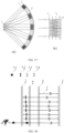
- FIG. 6 which shows a new linear array display structure proposed in this implementation.
- Light-emitting pixels 4a-1 of the linear array microdisplay and linear array display driver chips 4a-3 are connected by transparent wires 4a-2.
- the distance between the light-emitting pixel 4a-1 and the display driver chip 4a-3 is greater than 1 mm.
- a plurality of linear array display driver chips 4a-3 may be used to control a part of pixels respectively, such as 200 pixels. In this way, a size of a single control chip can be reduced, and the difficulty of wiring can be reduced. Certainly, a structure in which a single chip drives all the pixels is not excluded. Since the linear array display driver chip 4a-3 is generally opaque, the distance between the light-emitting pixel 4a-1 of the linear array microdisplay and the linear array display driver chip 4a-3 may be increased through the transparent wire 4a-2, such as 5 mm.
- FIG. 6(a) shows an arrangement of mirror symmetry of upper and lower parts of the light-emitting pixels 4a-1
- FIG. 6(b) shows an arrangement of symmetry of upper and lower parts of the light-emitting pixels 4a-1. Due to the rotating display, a complete image may also be formed by a one-round rotation of a half strip of the light-emitting pixels.
- FIG. 7 shows a linear array display arranged in a cross shape, in which the transparent wires 4a-2 are also used, and the linear array display driver chip 4a-3 may be placed on a side edge to prevent shading.
- the cross arrangement can increase the brightness of the rotating image and can also reduce the rotational speed required for rotation.
- a * -shaped arrangement including four lines may be provided. Details are not described herein.
- FIG. 8 is a schematic sectional view of an x-z plane of the linear array microdisplay. Regions 4a-4 on both sides of the light-emitting pixels may be non-functional transparent regions, or may function as the inner lens 2, i.e., configured as polarizing reflective surfaces. The inner lens 2 may be replaced.
- a front film layer 4a-5 for the light-emitting pixels may be a circular polarizing film or a linear polarizing film to change characteristics of the emitted light, and a size thereof is generally larger than a length covered by a light-emitting angle ensuring the exit pupil diameter of the system.
- a rotating concave ring 4a-8 is arranged on a back side of the center of the light-emitting pixels for rotation.
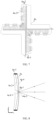
- FIG. 9 is a schematic assembly diagram.
- a rotating shaft 2-4 may be provided at the center of the inner lens 2 to limit the radial movement of the linear array microdisplay 4a.
- the central rotating shaft may be transparent to reduce central shading or may be opaque. However, a smaller size is better, such as a diameter of 0.5 mm.
- a fixed position of the rotating shaft may be on the inner lens 2, or on the linear array microdisplay 4a. Similar to a gemstone bearing in a watch, a material at the rotating position may be gemstones, so as to prolong a lifetime and improve precision.
- a wireless power supply receiving coil is configured to receive electric energy and supply power to a light-emitting device and a drive circuit.
- a photoelectric position detector such as an encoder is configured to acquire a precise position of rotation in real time, and other required peripheral electronic devices such as capacitors and inductors are further arranged.
- An inner magnetic ring 4a-7 of the linear array microdisplay may be fixed to an outer side of the extension end 4a-6 of the linear array microdisplay.
- An outer side of the inner magnetic ring 4a-7 of the linear array microdisplay is fixed to a frame 12.
- a restricting magnetic ring 8 is placed on the frame.
- the restricting magnetic ring 8 is in no contact with the inner magnetic ring 4a-7 of the linear array microdisplay, and the axial movement of the microdisplay 4 is restricted through a magnetic force.
- a drive coil, a wireless power supply coil, a position calibration ring, etc. may be arranged at an extension end 2-3 of the inner lens.
- the above devices may alternatively be separately placed on a supplementary function board 9 on which one or all of the drive coil, the wireless power supply coil, and the position calibration ring are arranged.
- the supplementary function board 9 is fixed to the frame 12.
- regions 4a-4 on both sides of the light-emitting pixel of the linear array microdisplay 4a when configured as partial reflective surfaces or polarizing reflective surfaces, can reflect light.
- the reflective film replaces the inner lens 2 to reflect light. Therefore, the inner lens 2 may be changed into a non-reflective inner protective lens 10 to protect a rotating structure and provide rotating support through a rotating shaft 10-1 of the inner protective lens in the middle thereof.
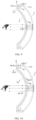
- the concave partial reflector 3 is configured as a strip-shaped partial reflector 3a, and the width thereof determines the exit pupil diameter, which is generally required to be larger than the human pupil, preferably within a range of 6 mm to 15 mm.
- the strip-shaped partial reflector 3a rotates synchronously with the linear array microdisplay 4a. In this case, the rotating structure for the linear array microdisplay 4a may be chosen from one of those in FIG. 9 and FIG. 10 .
- An outer protective lens 11 is placed on the outer side of the strip-shaped partial reflector 3a.
- a rotating shaft 11-1 of the outer protective lens may also be provided at the center of the outer protective lens 11 to support rotation, which may be similarly made of a transparent material. Since the rotating shafts are arranged in the front and back, the stability of rotation can be improved. In this case, an axial magnetic fixing structure formed by the restricting magnetic ring 8 and the inner magnetic ring 4a-7 of the linear array microdisplay can be canceled, but maintaining the structure can further improve the stability. In particular, when the user moves, the angular momentum of a rotating member may be changed, a magnetic force of an outer ring tends to generate a large moment to change the angular momentum of the rotating structure.
- FIG. 12 is a three-dimensional structural diagram of the linear array microdisplay 4a synchronously rotating with the strip-shaped concave reflector 3a.
- the light emitted by the microdisplay 4 first passes through the concave partial reflector 3 and reaches one surface of the inner lens 2.
- the one surface of the inner lens 2 is the concave surface 2-1 of the inner lens or the convex surface 2-2 of the inner lens, which has certain reflectivity and can reflect the light.
- the reflected light reaches the concave partial reflector 3 again.
- the concave partial reflector 3 reflects the light again, which is reflected again by one surface of the inner lens 2.
- the light, after being reflected again by the concave partial reflector 3, passes through the inner lens 2 and reaches the human eye.
- the total number of reflections of the light back and forth between the inner lens 2 and the concave partial reflector 3 is 4.
- the microdisplay 4 when the microdisplay 4 is located between the inner lens 2 and the concave partial reflector 3, the microdisplay 4 emits light toward the pupil position 1, and the number of reflections of the light between the inner lens 2 and the concave partial reflector 3 is 4.
- the light emitted by the microdisplay 4 first reaches one surface of the inner lens 2.
- the one surface of the inner lens 2 is the concave surface 2-1 of the inner lens or the convex surface 2-2 of the inner lens, which has certain reflectivity and can reflect the light.
- the reflected light passes through the microdisplay 4 and reaches the concave partial reflector 3 again.
- the concave partial reflector 3 reflects the light again, which passes through the microdisplay 4 and is reflected again by one surface.
- the light after passing through the microdisplay 4 and being reflected again by the concave partial reflector 3, passes through the microdisplay 4 and the inner lens 2 again and reaches the human eye.
- the total number of reflections of the light back and forth between the inner lens 2 and the concave partial reflector 3 is 4.
- the inner lens 2 is configured with a strip shape in the same direction as the pixel arrangement of the linear array microdisplay 4a, which rotates synchronously with the linear array microdisplay 4a.
- the center of the inner lens 2 is coated with a strip-shaped central total reflection film 13, and the width of the central total reflection film 13 should be smaller than the diameter of the human pupil, preferably within a range of 0.5 mm to 1.5 mm.
- one surface of the inner lens 2 i.e., the concave surface 2-1 or the convex surface 2-2, is configured as a polarizing reflective surface that reflects one type of polarized light and transmits another type of polarized light with a polarization direction perpendicular to that of the reflected light.
- a metal wire grid polarizing film has the above characteristics, which can be attached to a surface of an optical lens.
- a phase retardation plate 6 is added to the system to improve light energy efficiency.
- the phase retardation wave plate 6 is a quarter-wave plate.
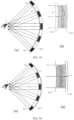
- FIG. 15(b) is a schematic diagram of polarization changes when the linear array microdisplay 4 is located between the inner lens 2 and the concave partial reflector 13.
- the microdisplay 4 emits the s-type linearly polarized light 7-3, which is reflected by the strip-shaped central total reflection film 13, with the polarization property unchanged.
- the reflected light passes through the phase retardation wave plate 6 and becomes the second circularly polarized light 7-4, which, after being reflected by one surface of the concave partial reflector 3, changes in the circular polarization direction and becomes the first circularly polarized light 7-3.
- the first circularly polarized light 7-3 passes through the phase retardation wave plate 6 again and becomes the p-type linearly polarized light 7-2, and then is completely reflected by the polarizing reflective film attached to one surface of the inner lens 2, with the polarization property unchanged.
- the reflected light passes through the phase retardation wave plate 6 again and becomes the first circularly polarized light 7-3, which, after being reflected by one surface of the concave partial reflector 3, changes in the circular polarization direction and becomes the second circularly polarized light 7-4.
- the second circularly polarized light 7-4 passes through the phase retardation wave plate 6 again and becomes the s-type linearly polarized light 7-1.
- the s-type linearly polarized light 7-1 can completely pass through the polarizing reflective film and reach the pupil position 1. Therefore, a display effect with high efficiency and low stray light is achieved.
- the linear array microdisplay 4a when the linear array microdisplay 4a is located on the right side of the concave partial reflector 3, only a polarization film layer is required to be placed in front of the linear array microdisplay 4a, so that the light arriving at the position of the central total reflection film 13 is the s-type linearly polarized light.
- the width of the polarization film layer should be small to prevent the passage of a large amount of light reflected by the central total reflection film 13, so that the light energy entering the human eye is reduced.
- FIG. 16(a) is a schematic assembly diagram of a system according to this embodiment in which the light is reflected 4 times when the linear array microdisplay 4a is used. Since the linear array microdisplay 4a is required to synchronously rotate with the strip-shaped inner lens 2, there is a need to add the inner protective lens 10 on a side close to the human eye and add the outer protective lens 11 on a side away from the human eye.
- FIG. 16(b) is an x-z sectional view of the linear array microdisplay 4a, in which the regions 4a-4 on both sides of the light-emitting pixels may be configured as partial reflective surfaces so as to replace functions of the concave partial reflector 3.
- the inner protective lens 10 and the outer protective lens 11 may be each provided with a rotating shaft, so as to improve stability.
- the rotating shaft may be made of a transparent material to prevent shading.
- the inner lens 2, the concave partial reflector 3, and the microdisplay 4 are distributed on concentric spherical surfaces, and the spherical center is at the center of the pupil position 1. Since the human eye has a zoom adjustment function, a certain degree of movement of each component or change of a surface shape is allowed. An additional function of this movement is to adapt to a degree of myopia and realize dynamic zoom. For example, a relative distance between the inner lens 1 and the concave partial reflector 3 may be dynamically adjusted to realize dynamic zoom. Generally, the zoom function may be realized by arranging a voice coil motor.
- Optical design parameters when a microdisplay 4 is between the inner lens 2 and the concave partial reflector 3 and the number of reflections is 4 are listed in the following table. The parameters start from a position of a virtual image. Since the positions and the shapes of the devices do not change during the folds, the parameters are only listed once.
- Optical design parameters when a microdisplay 4 is on the right side of the concave partial reflector 3 and the number of reflections is 4 are listed in the following table. The parameters start from a position of a virtual image. Since the positions and the shapes of the devices do not change during the folds, the parameters are only listed once.
- the curvature of the other surface may be changed as a surface for myopia correction to suit the degree of the user.
- Two surfaces of the concave partial reflector 3 may be treated in the same manner to adjust the degree.
- one surface of the concave partial reflector 3 may be coated with a reflective filter film.
- the film is designed according to the light-emitting wavelength of the microdisplay 4.
- the reflective filter film has high reflectivity for a light-emitting central wavelength of the microdisplay 4, for example, more than 90%, and has high transmittance for wavelengths other than the light-emitting central wavelength, for example, more than 90%.
- Such a design can improve the brightness of both the ambient light and the virtual image.
- the reflective filter film may be a dielectric film layer, a dielectric metal composite film layer, a holographic film layer, or a microstructure film layer.
- the light emitted by the microdisplay 4 is reflected back and forth between the concave partial reflector 3 and the inner lens 2 at least 5 times, and then passes through the inner lens 2 to reach the human eye.
- the microdisplay 4 is arranged between the inner lens 2 and the pupil position 1, the microdisplay 4 emits light away from the pupil position, and the number of reflections of the light emitted by the microdisplay 4 between the inner lens 2 and the concave partial reflector 3 is an odd number greater than or equal to 5, such as 7, 9, or 11.
- the microdisplay 4 When the microdisplay 4 is arranged between the inner lens 2 and the concave partial reflector 3, the microdisplay 4 may emit light away from the pupil position 1 or toward the pupil position 1.
- the number of reflections of the light emitted by the microdisplay 4 between the inner lens 2 and the concave partial reflector 3 is an odd number greater than or equal to 5, such as 7, 9, or 11.
- the number of reflections of the light emitted by the microdisplay 4 between the inner lens 2 and the concave partial reflector 3 is an even number greater than or equal to 6, such as 6, 8, or 10.
- the microdisplay 4 When the microdisplay 4 is arranged on the right side of the concave partial reflector 3, the microdisplay 4 emits light toward the pupil position 1, and the number of reflections of the light emitted by the microdisplay 4 between the inner lens 2 and the concave partial reflector 3 is an even number greater than or equal to 6, such as 6, 8, or 10.
- One surface of the inner lens 2 is configured as a switchable mirror.
- the microdisplay 4 is controlled to emit pulsed light.
- the switchable mirror reflects the light, and when the number of reflections reaches the set number, the switchable mirror becomes transmissive to transmit the light to the human eye. In this optical manner, the thickness can be further reduced.
- one surface of the inner lens 2 may be configured as a polarizing reflective surface
- a phase retardation wave plate 6 is added between the inner lens 2 and the concave partial reflector 3
- a partial reflective surface of the concave partial reflector 3 is configured as a surface that dynamically adjusts a reflection circular polarization direction
- the microdisplay 4 is controlled to emit pulsed circularly polarized light
- the concave partial reflector 3 is configured to keep a reflection circular polarization direction unchanged.
- FIG. 18 is a diagram showing optical path and polarization changes when the partial reflective surface of the concave partial reflector 3 is configured to dynamically adjust the reflection circular polarization direction.
- the function of dynamically adjusting the reflection circular polarization direction can be realized through metasurface technology.
- the microdisplay 4 emits short-pulse first circularly polarized light 7-3.
- the concave partial reflector 3 is configured to keep a reflection circular polarization direction unchanged.
- the light, after being reflected passes through the phase retardation wave plate 6 and becomes the p-type linearly polarized light 7-2.
- the p-type linearly polarized light 7-2 is completely reflected by the polarizing reflective film on the inner lens 2, passes through the phase retardation wave plate 6, and is then still the first circularly polarized light 7-3. After the light is reflected back and forth the designed times such as 8 times, the partial reflective surface of the concave partial reflector 3 becomes a normal mirror surface. After the reflection, the circular polarization direction is reversed and becomes the second circularly polarized light 7-4, which finally passes through the phase retardation wave plate 6 and becomes s-type linearly polarized light that passes through the inner lens 2 and enters the human eye.
- Optical design parameters for a system with multiple reflections shown in FIG. 17 are listed in the following table.
- the parameters in the table correspond to a situation where the microdisplay 4 is located between the inner lens 2 and the concave partial reflector 3.
- the parameters start from a position of a virtual image. Since the positions and the shapes of the devices do not change during the folds, the parameters are only listed once.
- the microdisplay 4 may be placed on the left side or right side of the integrated lens 14.
- the light after being reflected back and forth between an inner surface 14-1 of the integrated lens and an outer surface 14-2 of the integrated lens a set number of times such as 8 times, enters the human eye through the inner surface 14-1 of the integrated lens.
- the integrated lens 14 and the microdisplay 4 are distributed on concentric spherical surfaces, and the spherical center is at the center of the pupil position 1. Since the human eye has a zoom adjustment function, a certain degree of movement of each component or change of a surface shape is allowed. An additional function of this movement is to adapt to a degree of myopia and realize dynamic zoom. Generally, the zoom function can be implemented by arranging a voice coil motor.
- Optical design parameters for a system shown in FIG. 19 are listed in the following table. Data in the table indicates that the microdisplay 4 is located on the left side of the integrated lens 14. The parameters start from a position of a virtual image. Since the positions and the shapes of the devices do not change during the folds, the parameters are only listed once.
- the inner surface 14-1 of the integrated lens may be configured as a switchable mirror, and transmission or reflection of the switchable mirror may be electronically controlled.
- the microdisplay 4 emits pulsed light. When the number of reflections does not reach the set number, the switchable mirror can reflect the light, and when the number of reflections reaches the set number, the switchable mirror becomes transmissive to transmit the light into the human eye. An effect with high efficiency and low stray light can be achieved.
Landscapes
- Physics & Mathematics (AREA)
- General Physics & Mathematics (AREA)
- Optics & Photonics (AREA)
- Engineering & Computer Science (AREA)
- Multimedia (AREA)
- Signal Processing (AREA)
- Devices For Indicating Variable Information By Combining Individual Elements (AREA)
Applications Claiming Priority (2)
| Application Number | Priority Date | Filing Date | Title |
|---|---|---|---|
| CN202110297398.XA CN112799232B (zh) | 2021-03-19 | 2021-03-19 | 一种轻便短焦近眼显示系统 |
| PCT/CN2022/071799 WO2022193808A1 (fr) | 2021-03-19 | 2022-01-13 | Système d'affichage proche de l'œil à foyer court de la lumière |
Publications (2)
| Publication Number | Publication Date |
|---|---|
| EP4310577A1 true EP4310577A1 (fr) | 2024-01-24 |
| EP4310577A4 EP4310577A4 (fr) | 2024-09-04 |
Family
ID=75817273
Family Applications (1)
| Application Number | Title | Priority Date | Filing Date |
|---|---|---|---|
| EP22770170.3A Withdrawn EP4310577A4 (fr) | 2021-03-19 | 2022-01-13 | Système d'affichage proche de l'oeil à foyer court de la lumière |
Country Status (6)
| Country | Link |
|---|---|
| US (1) | US12517362B2 (fr) |
| EP (1) | EP4310577A4 (fr) |
| JP (1) | JP7624769B2 (fr) |
| KR (1) | KR102919704B1 (fr) |
| CN (1) | CN112799232B (fr) |
| WO (1) | WO2022193808A1 (fr) |
Families Citing this family (10)
| Publication number | Priority date | Publication date | Assignee | Title |
|---|---|---|---|---|
| JP2022039294A (ja) * | 2020-08-28 | 2022-03-10 | セイコーエプソン株式会社 | 虚像表示装置及び光学ユニット |
| CN112799232B (zh) | 2021-03-19 | 2025-11-07 | 光感(上海)科技有限公司 | 一种轻便短焦近眼显示系统 |
| KR20230004293A (ko) * | 2021-06-30 | 2023-01-06 | 이문기 | 원편광을 이용한 착용형 디스플레이 |
| CN113820862B (zh) * | 2021-09-10 | 2023-06-27 | 维沃移动通信有限公司 | 光学镜片和光学眼镜 |
| CN113866984B (zh) * | 2021-09-27 | 2022-08-30 | 业成科技(成都)有限公司 | 短焦光学模组 |
| TWI813395B (zh) * | 2022-07-22 | 2023-08-21 | 新鉅科技股份有限公司 | 光學透鏡組和頭戴式電子裝置 |
| CN115373149A (zh) * | 2022-09-05 | 2022-11-22 | 业成科技(成都)有限公司 | 头戴显示设备 |
| WO2025021446A1 (fr) * | 2023-07-21 | 2025-01-30 | Ams-Osram Ag | Élément optique |
| CN116699853B (zh) * | 2023-07-27 | 2023-11-03 | 北京极溯光学科技有限公司 | 一种大视场角光学系统及ar设备 |
| CN118732218B (zh) * | 2024-07-29 | 2025-08-29 | 惠科股份有限公司 | 远像显示器 |
Family Cites Families (25)
| Publication number | Priority date | Publication date | Assignee | Title |
|---|---|---|---|---|
| JP3212784B2 (ja) * | 1993-12-21 | 2001-09-25 | オリンパス光学工業株式会社 | 視覚表示装置 |
| JP5496166B2 (ja) * | 2011-11-02 | 2014-05-21 | 三菱電機株式会社 | 表示装置 |
| US9581821B2 (en) * | 2014-06-24 | 2017-02-28 | Fakespace Labs, Inc. | Head mounted augmented reality display |
| EP3195055A1 (fr) * | 2015-09-03 | 2017-07-26 | 3M Innovative Properties Company | Système optique |
| CN109313340A (zh) * | 2016-02-01 | 2019-02-05 | 寇平公司 | 嵌入式反射目镜 |
| US10095036B2 (en) * | 2016-02-04 | 2018-10-09 | Google Llc | Compact near-eye display optics |
| US11054648B2 (en) * | 2016-02-04 | 2021-07-06 | Google Llc | Compact near-eye display optics for higher optical performance |
| CN109313287B (zh) * | 2016-06-09 | 2021-07-09 | 3M创新有限公司 | 显示系统和光导 |
| US10394040B2 (en) * | 2016-10-12 | 2019-08-27 | Facebook Technologies, Llc | Head mounted display including pancake lens block |
| US10739586B1 (en) * | 2017-08-07 | 2020-08-11 | Facebook Technologies, Llc | Reflective polarizer for augmented reality and virtual reality display |
| CN108319018A (zh) * | 2018-02-12 | 2018-07-24 | 杭州太若科技有限公司 | 一种增强现实装置、设备及实现增强现实的方法 |
| US11226483B2 (en) * | 2018-06-07 | 2022-01-18 | Facebook Technologies, Llc | Reverse-order crossed pancake lens with a shaped polarizer |
| US20200041790A1 (en) * | 2018-08-02 | 2020-02-06 | Google Llc | Catadioptric freeform head mounted display |
| WO2020049724A1 (fr) * | 2018-09-07 | 2020-03-12 | 株式会社島津製作所 | Dispositif d'affichage |
| EP3698203B1 (fr) * | 2018-10-05 | 2024-05-22 | Google LLC | Visiocasque avec balayage mécanique |
| CN212060744U (zh) | 2019-12-05 | 2020-12-01 | 光感(上海)科技有限公司 | 一种近眼显示光学系统 |
| CN110780447A (zh) * | 2019-12-05 | 2020-02-11 | 杨建明 | 一种用于增强现实眼镜的光学系统 |
| CN111123522A (zh) * | 2020-01-17 | 2020-05-08 | 光感(上海)科技有限公司 | 一种增强现实眼镜的光学系统 |
| CN212302096U (zh) * | 2020-01-17 | 2021-01-05 | 光感(上海)科技有限公司 | 一种近眼显示光学系统 |
| CN211318884U (zh) * | 2020-03-19 | 2020-08-21 | 宁波鸿蚁光电科技有限公司 | 一种轻薄型光学显示系统、影像镜头模组及vr设备 |
| CN111638602B (zh) * | 2020-07-03 | 2022-05-24 | 维沃移动通信有限公司 | 光学装置及近眼显示设备 |
| CN112904563A (zh) | 2021-02-04 | 2021-06-04 | 光感(上海)科技有限公司 | 一种短焦近眼显示系统 |
| CN112799232B (zh) * | 2021-03-19 | 2025-11-07 | 光感(上海)科技有限公司 | 一种轻便短焦近眼显示系统 |
| CN214540237U (zh) * | 2021-03-19 | 2021-10-29 | 光感(上海)科技有限公司 | 一种轻便短焦近眼显示系统 |
| CN115639675A (zh) | 2022-11-02 | 2023-01-24 | 光感(上海)科技有限公司 | 一种旋转导光显示系统 |
-
2021
- 2021-03-19 CN CN202110297398.XA patent/CN112799232B/zh active Active
-
2022
- 2022-01-13 KR KR1020237031350A patent/KR102919704B1/ko active Active
- 2022-01-13 EP EP22770170.3A patent/EP4310577A4/fr not_active Withdrawn
- 2022-01-13 US US18/550,156 patent/US12517362B2/en active Active
- 2022-01-13 WO PCT/CN2022/071799 patent/WO2022193808A1/fr not_active Ceased
- 2022-01-13 JP JP2023554335A patent/JP7624769B2/ja active Active
Also Published As
| Publication number | Publication date |
|---|---|
| US12517362B2 (en) | 2026-01-06 |
| EP4310577A4 (fr) | 2024-09-04 |
| WO2022193808A1 (fr) | 2022-09-22 |
| CN112799232B (zh) | 2025-11-07 |
| KR20230142798A (ko) | 2023-10-11 |
| KR102919704B1 (ko) | 2026-01-28 |
| JP7624769B2 (ja) | 2025-01-31 |
| JP2024509565A (ja) | 2024-03-04 |
| CN112799232A (zh) | 2021-05-14 |
| US20240151979A1 (en) | 2024-05-09 |
Similar Documents
| Publication | Publication Date | Title |
|---|---|---|
| EP4310577A1 (fr) | Système d'affichage proche de l'oeil à foyer court de la lumière | |
| JP7076891B2 (ja) | 視標追跡機能を備えるヘッドマウント式ディスプレイ | |
| US12013538B2 (en) | Augmented reality (AR) eyewear with a section of a fresnel reflector comprising individually-adjustable transmissive-reflective optical elements | |
| US10598937B2 (en) | Polarizing optical system | |
| US7133207B2 (en) | Micro-display engine | |
| AU2004271392B2 (en) | Substrate-guided optical devices | |
| CN102023383B (zh) | 眼镜型图像显示装置 | |
| Sarayeddine et al. | Key challenges to affordable see-through wearable displays: the missing link for mobile AR mass deployment | |
| CN112292629A (zh) | 光学装置和头戴式显示器 | |
| TW202314328A (zh) | 短焦光學模組 | |
| US20220390744A1 (en) | Near-eye display system having multiple pass in-coupling for waveguide display | |
| KR20200105946A (ko) | 가상 및 혼합 현실을 위한 크로스형 구성의 소형 광학 기기 | |
| EP4010750A2 (fr) | Système optique proche de l'oeil mettant en oeuvre un guide d'ondes avec un élément de visualisation de sortie ayant une lentille convexe de division de faisceau de réfraction | |
| EP4290293A1 (fr) | Système d'affichage proche de l'oeil à foyer court | |
| WO2021055230A1 (fr) | Systèmes optiques à affichages périphériques à basse résolution | |
| WO2017223167A1 (fr) | Optique de dispositifs d'affichage portables | |
| CN220208002U (zh) | 一种大视场轻量化头戴显示装置 | |
| JP2020020859A (ja) | 虚像表示装置 | |
| CN117075337A (zh) | 光学模组以及头戴显示设备 | |
| CN214540237U (zh) | 一种轻便短焦近眼显示系统 | |
| US12339450B2 (en) | Total reflection based compact near-eye display device with large field of view | |
| CN107765434B (zh) | 一种单像源双目近眼显示装置 | |
| US12205231B2 (en) | Holovisions™—adjustable and/or modular augmented reality (AR) eyewear with a movable transflective mirror and different viewing modes | |
| US20240345389A1 (en) | Waveguide based imaging system for object tracking and waveguide based display system for reducing world side ghost | |
| WO2024215645A2 (fr) | Système d'imagerie basé sur un guide d'ondes pour suivi d'objet et système d'affichage basé sur un guide d'ondes pour réduire un fantôme côté monde |
Legal Events
| Date | Code | Title | Description |
|---|---|---|---|
| STAA | Information on the status of an ep patent application or granted ep patent |
Free format text: STATUS: THE INTERNATIONAL PUBLICATION HAS BEEN MADE |
|
| PUAI | Public reference made under article 153(3) epc to a published international application that has entered the european phase |
Free format text: ORIGINAL CODE: 0009012 |
|
| STAA | Information on the status of an ep patent application or granted ep patent |
Free format text: STATUS: REQUEST FOR EXAMINATION WAS MADE |
|
| 17P | Request for examination filed |
Effective date: 20231018 |
|
| AK | Designated contracting states |
Kind code of ref document: A1 Designated state(s): AL AT BE BG CH CY CZ DE DK EE ES FI FR GB GR HR HU IE IS IT LI LT LU LV MC MK MT NL NO PL PT RO RS SE SI SK SM TR |
|
| DAV | Request for validation of the european patent (deleted) | ||
| DAX | Request for extension of the european patent (deleted) | ||
| A4 | Supplementary search report drawn up and despatched |
Effective date: 20240801 |
|
| RIC1 | Information provided on ipc code assigned before grant |
Ipc: G02B 17/06 20060101ALI20240726BHEP Ipc: G02B 27/28 20060101ALI20240726BHEP Ipc: G02B 27/01 20060101AFI20240726BHEP |
|
| STAA | Information on the status of an ep patent application or granted ep patent |
Free format text: STATUS: THE APPLICATION HAS BEEN WITHDRAWN |
|
| 18W | Application withdrawn |
Effective date: 20260119 |