EP4310980A2 - Électrode multicouche pour batterie et son procédé de fabrication - Google Patents
Électrode multicouche pour batterie et son procédé de fabrication Download PDFInfo
- Publication number
- EP4310980A2 EP4310980A2 EP23215354.4A EP23215354A EP4310980A2 EP 4310980 A2 EP4310980 A2 EP 4310980A2 EP 23215354 A EP23215354 A EP 23215354A EP 4310980 A2 EP4310980 A2 EP 4310980A2
- Authority
- EP
- European Patent Office
- Prior art keywords
- binder
- current collector
- binder solution
- electrode active
- active material
- Prior art date
- Legal status (The legal status is an assumption and is not a legal conclusion. Google has not performed a legal analysis and makes no representation as to the accuracy of the status listed.)
- Pending
Links
Images
Classifications
-
- H—ELECTRICITY
- H01—ELECTRIC ELEMENTS
- H01M—PROCESSES OR MEANS, e.g. BATTERIES, FOR THE DIRECT CONVERSION OF CHEMICAL ENERGY INTO ELECTRICAL ENERGY
- H01M4/00—Electrodes
- H01M4/02—Electrodes composed of, or comprising, active material
- H01M4/13—Electrodes for accumulators with non-aqueous electrolyte, e.g. for lithium-accumulators; Processes of manufacture thereof
- H01M4/139—Processes of manufacture
- H01M4/1393—Processes of manufacture of electrodes based on carbonaceous material, e.g. graphite-intercalation compounds or CFx
-
- H—ELECTRICITY
- H01—ELECTRIC ELEMENTS
- H01M—PROCESSES OR MEANS, e.g. BATTERIES, FOR THE DIRECT CONVERSION OF CHEMICAL ENERGY INTO ELECTRICAL ENERGY
- H01M4/00—Electrodes
- H01M4/02—Electrodes composed of, or comprising, active material
- H01M4/04—Processes of manufacture in general
- H01M4/0402—Methods of deposition of the material
- H01M4/0404—Methods of deposition of the material by coating on electrode collectors
-
- H—ELECTRICITY
- H01—ELECTRIC ELEMENTS
- H01M—PROCESSES OR MEANS, e.g. BATTERIES, FOR THE DIRECT CONVERSION OF CHEMICAL ENERGY INTO ELECTRICAL ENERGY
- H01M10/00—Secondary cells; Manufacture thereof
- H01M10/05—Accumulators with non-aqueous electrolyte
- H01M10/052—Li-accumulators
-
- H—ELECTRICITY
- H01—ELECTRIC ELEMENTS
- H01M—PROCESSES OR MEANS, e.g. BATTERIES, FOR THE DIRECT CONVERSION OF CHEMICAL ENERGY INTO ELECTRICAL ENERGY
- H01M10/00—Secondary cells; Manufacture thereof
- H01M10/05—Accumulators with non-aqueous electrolyte
- H01M10/052—Li-accumulators
- H01M10/0525—Rocking-chair batteries, i.e. batteries with lithium insertion or intercalation in both electrodes; Lithium-ion batteries
-
- H—ELECTRICITY
- H01—ELECTRIC ELEMENTS
- H01M—PROCESSES OR MEANS, e.g. BATTERIES, FOR THE DIRECT CONVERSION OF CHEMICAL ENERGY INTO ELECTRICAL ENERGY
- H01M10/00—Secondary cells; Manufacture thereof
- H01M10/05—Accumulators with non-aqueous electrolyte
- H01M10/058—Construction or manufacture
-
- H—ELECTRICITY
- H01—ELECTRIC ELEMENTS
- H01M—PROCESSES OR MEANS, e.g. BATTERIES, FOR THE DIRECT CONVERSION OF CHEMICAL ENERGY INTO ELECTRICAL ENERGY
- H01M10/00—Secondary cells; Manufacture thereof
- H01M10/42—Methods or arrangements for servicing or maintenance of secondary cells or secondary half-cells
- H01M10/4235—Safety or regulating additives or arrangements in electrodes, separators or electrolyte
-
- H—ELECTRICITY
- H01—ELECTRIC ELEMENTS
- H01M—PROCESSES OR MEANS, e.g. BATTERIES, FOR THE DIRECT CONVERSION OF CHEMICAL ENERGY INTO ELECTRICAL ENERGY
- H01M4/00—Electrodes
- H01M4/02—Electrodes composed of, or comprising, active material
- H01M4/13—Electrodes for accumulators with non-aqueous electrolyte, e.g. for lithium-accumulators; Processes of manufacture thereof
-
- H—ELECTRICITY
- H01—ELECTRIC ELEMENTS
- H01M—PROCESSES OR MEANS, e.g. BATTERIES, FOR THE DIRECT CONVERSION OF CHEMICAL ENERGY INTO ELECTRICAL ENERGY
- H01M4/00—Electrodes
- H01M4/02—Electrodes composed of, or comprising, active material
- H01M4/13—Electrodes for accumulators with non-aqueous electrolyte, e.g. for lithium-accumulators; Processes of manufacture thereof
- H01M4/139—Processes of manufacture
-
- H—ELECTRICITY
- H01—ELECTRIC ELEMENTS
- H01M—PROCESSES OR MEANS, e.g. BATTERIES, FOR THE DIRECT CONVERSION OF CHEMICAL ENERGY INTO ELECTRICAL ENERGY
- H01M4/00—Electrodes
- H01M4/02—Electrodes composed of, or comprising, active material
- H01M4/36—Selection of substances as active materials, active masses, active liquids
- H01M4/58—Selection of substances as active materials, active masses, active liquids of inorganic compounds other than oxides or hydroxides, e.g. sulfides, selenides, tellurides, halogenides or LiCoFy; of polyanionic structures, e.g. phosphates, silicates or borates
- H01M4/583—Carbonaceous material, e.g. graphite-intercalation compounds or CFx
- H01M4/587—Carbonaceous material, e.g. graphite-intercalation compounds or CFx for inserting or intercalating light metals
-
- H—ELECTRICITY
- H01—ELECTRIC ELEMENTS
- H01M—PROCESSES OR MEANS, e.g. BATTERIES, FOR THE DIRECT CONVERSION OF CHEMICAL ENERGY INTO ELECTRICAL ENERGY
- H01M4/00—Electrodes
- H01M4/02—Electrodes composed of, or comprising, active material
- H01M4/62—Selection of inactive substances as ingredients for active masses, e.g. binders, fillers
-
- H—ELECTRICITY
- H01—ELECTRIC ELEMENTS
- H01M—PROCESSES OR MEANS, e.g. BATTERIES, FOR THE DIRECT CONVERSION OF CHEMICAL ENERGY INTO ELECTRICAL ENERGY
- H01M4/00—Electrodes
- H01M4/02—Electrodes composed of, or comprising, active material
- H01M4/62—Selection of inactive substances as ingredients for active masses, e.g. binders, fillers
- H01M4/621—Binders
-
- H—ELECTRICITY
- H01—ELECTRIC ELEMENTS
- H01M—PROCESSES OR MEANS, e.g. BATTERIES, FOR THE DIRECT CONVERSION OF CHEMICAL ENERGY INTO ELECTRICAL ENERGY
- H01M4/00—Electrodes
- H01M4/02—Electrodes composed of, or comprising, active material
- H01M4/64—Carriers or collectors
- H01M4/66—Selection of materials
-
- H—ELECTRICITY
- H01—ELECTRIC ELEMENTS
- H01M—PROCESSES OR MEANS, e.g. BATTERIES, FOR THE DIRECT CONVERSION OF CHEMICAL ENERGY INTO ELECTRICAL ENERGY
- H01M4/00—Electrodes
- H01M4/02—Electrodes composed of, or comprising, active material
- H01M2004/021—Physical characteristics, e.g. porosity, surface area
-
- Y—GENERAL TAGGING OF NEW TECHNOLOGICAL DEVELOPMENTS; GENERAL TAGGING OF CROSS-SECTIONAL TECHNOLOGIES SPANNING OVER SEVERAL SECTIONS OF THE IPC; TECHNICAL SUBJECTS COVERED BY FORMER USPC CROSS-REFERENCE ART COLLECTIONS [XRACs] AND DIGESTS
- Y02—TECHNOLOGIES OR APPLICATIONS FOR MITIGATION OR ADAPTATION AGAINST CLIMATE CHANGE
- Y02E—REDUCTION OF GREENHOUSE GAS [GHG] EMISSIONS, RELATED TO ENERGY GENERATION, TRANSMISSION OR DISTRIBUTION
- Y02E60/00—Enabling technologies; Technologies with a potential or indirect contribution to GHG emissions mitigation
- Y02E60/10—Energy storage using batteries
Definitions
- the following disclosure relates to a multi-layered electrode for a battery and a fabrication method thereof.
- binders having high adhesion have been developed and a technology for lowering the content of binders has been developed, but there is a limit in types of binders having high adhesion and to lowering a binder content, and a serious problem may occur in that an electrode mixture layer is detached from the current collector during the process or charging/discharging process, and if the binder content is too low, a serious problem may occur in that an electrode composition layer is detached from a current collector during a notching process or the charging/discharging process.
- the binder content is formed to be higher at an interface of a current collector, thereby suppressing detachment, while lowering the binder content in the electrode mixture layer and a surface, to improve battery performance.
- An embodiment of the present invention is directed to solving a problem arising as solid content in a lower binder solution are not maintained in a uniform distribution when electrode slurry is applied to an upper part of a binder solution during a process of forming an electrode active material layer by applying the binder solution and the electrode slurry onto a current collector, that is a problem of a degradation of adhesion between the current collector and the electrode active material layer.
- a fabrication method of a multi-layered electrode for a battery includes: (a) applying a binder solution including a conductive material, a magnetic material and a binder on a current collector; (b) applying a magnetic field to the current collector to which the binder solution is applied; and (c) applying an electrode slurry including an electrode active material on the binder solution, wherein the magnetic material is coated on the entire or partial surface of the conductive material.
- a content of solid content in the binder solution may be 0.5 to 50 wt%.
- Viscosity of the binder solution in step (a) may be 500 cp or less.
- the magnetic material may be included in an amount of 0.5 to 20 parts by weight with respect to 100 parts by weight of the conductive material.
- a weight ratio of the magnetic material and the binder in the binder solution may be 1: 20 to 1: 80.
- a content of the magnetic material in the binder solution may be 0.1 to 5 wt%.
- the magnetic material may include at least one selected from the group consisting of iron (Fe), nickel (Ni), and cobalt (Co).
- the conductive material may include at least one selected from the group consisting of natural graphite, artificial graphite, carbon black, acetylene black, ketjen black, carbon fibers, and carbon nanotubes.
- the binder may be a water-soluble binder.
- Step (b) may be applying a magnetic field in a direction perpendicular to the current collector.
- the magnetic field applied in step (b) may be a unidirectional magnetic field formed by a magnetic device positioned above and below the current collector.
- Step (b) may be applying a magnetic field so that the conductive material coated with the magnetic material and the binder form an aggregate in the binder solution.
- a strength of the magnetic field may be 100 to 5000 G, and a magnetic field application time may be 1 second to 60 seconds.
- Viscosity of the binder solution before and after the application of the magnetic field may satisfy Relational Expression 1 below. 1.2 ⁇ A 2 / A 1 ⁇ 5
- a 1 is a viscosity of the binder solution before the magnetic field is applied
- a 2 is a viscosity of the binder solution when the electrode slurry is applied after the magnetic field is applied.
- the method may further include (d) performing drying, after step (c), wherein the viscosity of the binder solution during drying may be 100 to 5000 cp.
- a multi-layered electrode for a secondary battery including a current collector; and an electrode active material layer containing a conductive material, a magnetic material and a binder formed on the current collector, wherein the magnetic material is coated on the entire or partial surface of the conductive material.
- the electrode active material layer may include an aggregate formed by agglomerating the conductive material coated with the magnetic material and the binder.
- the electrode active material layer may have a difference between a maximum loading value and a minimum loading value of the electrode active material layer in at least five positions at regular intervals in a width direction may be 10% or less of a total loading average value.
- the multi-layered electrode may satisfy Relational Expression 2 below. 0.2 ⁇ B 2 / B 1 ⁇ 0.8
- B 1 is a weight of the binder in the entire electrode active material layer
- B 2 is a weight of the binder in a region of 15% of a total thickness of the electrode active material layer from the current collector.
- Adhesion of the electrode active material layer with respect to the current collector may be 0.2 N/cm or more.
- the multi-layered electrode may satisfy Relational Expression 3 below. ⁇ 30 % ⁇ C ⁇ D / D ⁇ + 30 %
- C is an interfacial adhesion between the current collector and the electrode active material layer measured at a certain position selected in a width direction of the electrode active material layer
- D is an average value of the interfacial adhesion between the current collector and the electrode active material layer.
- a secondary battery in another general aspect, includes a multi-layered electrode; a separator; and an electrolyte.
- viscosity is a value measured at a shear rate of 1 s -1 using a Brookfield rotational viscometer at room temperature and pressure conditions, and tolerance is ⁇ 100 cP.
- the present invention provides a fabrication method of a multi-layered electrode for a battery including: (a) applying a binder solution including magnetic material on a current collector; (b) applying a magnetic field to the current collector to which the binder solution is applied; and (c) applying an electrode slurry including an electrode active material on the binder solution.
- a binder solution including a magnetic material, a binder, and a solvent is prepared.
- the binder solution refers to a mixture in which the binder is not dissolved and exists in the form of particles in a solvent, and a thickener, a conductive material, etc. may be additionally mixed and used as necessary.
- a solid content in the binder solution excluding the solvent may be included in an amount of 0.5 to 50 wt%, specifically 10 to 40 wt%.
- viscosity of the binder solution may be 500 cp or less, specifically, 100 to 500 cp.
- the binder may be a water-soluble binder, and specifically, styrene-butadiene rubber, acrylated styrene-butadiene rubber, polyvinyl alcohol, sodium polyacrylate, propylene, and an olefin copolymer having 2 to 8 carbon atoms, a copolymer of (meth)acrylic acid and (meth)acrylic acid alkyl ester, or a combination thereof.
- the binder solution may include 0.1 to 50 wt% of the binder, preferably, 10 to 30 wt%, based on a total weight.
- the total amount of binders included in the entire active material layer may be significantly reduced. Accordingly, interfacial adhesion between the current collector and the electrode active material layer may be improved and fast charging performance may also be improved.
- the magnetic material may include at least one selected from the group consisting of iron (Fe), nickel (Ni), and cobalt (Co).
- the magnetic material may be in the form of particles having a particle size of 50 nm to 5 um.
- the magnetic material may form an aggregate with the solid particles in the binder solution and the aggregate may form a chain structure in the solution to increase the viscosity of the binder solution. Accordingly, the fabrication method of a multi-layered electrode for a secondary battery according to the present invention may suppress a non-uniform distribution of the solid content, particularly the binder, in a lower binder solution that occurs during a subsequent application of an upper electrode slurry.
- the magnetic material may exist in a state of being coated on a conductive material.
- a coating method is not particularly limited, but a solution method may be used as a non-limiting example.
- 0.5 to 20 parts by weight of the magnetic material preferably, 1 to 10 parts by weight, may be included with respect to 100 parts by weight of the conductive material.
- the conductive material is used to impart conductivity to the electrode, and is not particularly limited as long as a material is a conventional electronically conductive material that does not cause chemical change in the battery.
- a material is a conventional electronically conductive material that does not cause chemical change in the battery.
- natural graphite, artificial graphite, carbon black, acetylene black, ketjen black, carbon fibers, carbon nanotubes, and combinations thereof may be used, but is not limited thereto.
- a weight ratio of the magnetic material and the binder in the binder solution may be 1: 20 to 1: 80, preferably, 1: 40 to 1: 80. More specifically, the content of the magnetic material in the binder solution may be 0.1 to 5 wt%, preferably, 0.1 to 1 wt%.
- the solvent may be at least one selected from the group consisting of water, pure water, deionized water, distilled water, ethanol, isopropanol, methanol, acetone, n-propanol and t-butanol, but is not limited thereto.
- the binder solution may further include a thickener for making a stable solution by imparting viscosity.
- the thickener may be used by mixing one or more of a cellulose-based compound, specifically, carboxymethyl cellulose, hydroxypropylmethyl cellulose, methyl cellulose, or alkali metal salts thereof.
- a cellulose-based compound specifically, carboxymethyl cellulose, hydroxypropylmethyl cellulose, methyl cellulose, or alkali metal salts thereof.
- alkali metal Na, K or Li may be used.
- the current collector one selected from the group consisting of copper foil, nickel foil, stainless steel foil, titanium foil, nickel foam, copper foam, a polymer substrate coated with conductive metal, and combinations thereof may be used, but is not limited thereto.
- the binder solution may be applied to have a thickness of 1 to 20 um. More specifically, a coating thickness of the binder solution may be 1 to 5 ⁇ m. If the thickness of the applied binder solution is excessive, the binder solution may not be mixed easily with the electrode slurry, so that a separation between the layers may be apparent after drying, and a binder layer, which is an insulator, may be formed to increase interfacial resistance. Meanwhile, if the coating thickness of the binder solution is less than 1 ⁇ m, it may be difficult to achieve the intended purpose of the present invention. That is, in the aforementioned thickness range, the interfacial resistance may be reduced, interfacial adhesion between the current collector and the electrode active material layer may be improved, and process defects such as electrode detachment may be improved.
- any coating method known to be used for forming a film by generally applying a liquid phase may be used for the coating.
- spray coating, dip coating, spin coating, gravure coating, slot die coating, doctor blade coating, roll coating, inkjet printing, lexography printing, screen printing, electrostatic hydrodynamic printing, micro contact printing, imprinting, reverse offset printing, bar-coating, gravure offset printing, etc. may be used, but are not limited thereto.
- step (b) a magnetic field is applied to the current collector to which the binder solution is applied.
- the magnetic field may be a unidirectional magnetic field formed by magnetic devices positioned above and below the current collector.
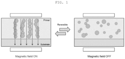
- FIG. 1 is a view illustrating a change in array of solid particles in a binder solution when a magnetic field is applied according to an embodiment of the present invention.
- the solid particles in the binder solution may be arranged in a direction of the magnetic field by the magnetic material to form a chain structure and have characteristics similar to those of a solid, thereby increasing the viscosity of the binder solution.
- the magnetic field when the magnetic field is not applied, the solid particles in the binder solution return to their original fluid state, thereby lowering the viscosity of the binder solution to 500 cp or less, which is an initial state.
- the strength of the magnetic field may be 100 to 5000 G, preferably, 500 to 3000 G, and, more preferably, 2000 to 3000 G, and a magnetic field application time may be 1 second to 60 seconds, preferably, 10 seconds to 60 seconds, more preferably, 30 seconds to 60 seconds.
- the viscosity of the lower binder solution may be increased, so that the distribution of the solid content in the binder solution may be maintained uniformly even after the electrode slurry is applied to the upper part. Accordingly, a phenomenon in which the loading amount of the solid content at the center and the edge of the current collector is not maintained at the initial uniform state so the interfacial adhesion between the current collector and the electrode active material layer is reduced may be suppressed.
- the viscosity of the binder solution before and after the application of the magnetic field under the above conditions may satisfy Relational Expression 1 below. 1.2 ⁇ A 2 / A 1 ⁇ 5
- a 1 is the viscosity of the binder solution before the magnetic field is applied
- a 2 is the viscosity of the binder solution when the electrode slurry is applied after the magnetic field is applied.
- a 1 is the viscosity of the binder solution before the magnetic field is applied, and may be 500 cp or less, specifically, 100 to 500 cp
- a 2 is the viscosity of the binder solution when the electrode slurry is applied after the magnetic field is applied, specifically, may be the viscosity of the binder solution before a drying process.
- a uniform distribution of the binders in the lower binder solution may be uniformly maintained, thereby improving adhesion, as well as problems such as the lower binder solution being pushed by a strong discharge pressure of the upper electrode slurry in a mass-production process.
- step (c) the electrode slurry including the electrode active material is applied on the binder solution.
- the electrode active material may be an electrode active material typically used in secondary batteries.
- a negative electrode active material may be, for example, a carbon-based negative electrode active material, a silicone-based negative electrode active material, or a mixture thereof, but is not limited thereto.
- the carbon-based negative electrode active material may be one or more selected from the group consisting of artificial graphite, natural graphite, and hard carbon.
- the silicone-based negative electrode active material may be Si, SiO x (0 ⁇ x ⁇ 2), an Si-Q alloy (Q is an element selected from the group consisting of alkali metal, alkaline earth metal, group 13 element, group 14 element, group 15 element, group 16 element, transition metal, rare earth element, and combinations thereof, and not Si), a Si-carbon composite, or a mixture of at least one thereof and SiO 2 .
- a positive electrode active material may be a composite oxide of lithium and a metal selected from among cobalt, manganese, nickel, and combinations thereof, but is not limited thereto.
- the application of the electrode slurry is the same as the application of the binder solution described above, and any method known to be used for forming a known electrode slurry for a secondary battery may be used.
- the method may further include step (d) of drying a result of step (c) after step (c).
- the drying may be performed at a temperature of 80 to 130°C, preferably, 100 to 130°C, for 10 to 50 minutes, preferably, 15 to 30 minutes.
- the viscosity of the binder solution applied on the current collector during drying may be 100 to 5000 cp, preferably, 200 to 2000 cp.
- the dried electrode may be rolled to have an appropriate density to fabricate an electrode having the electrode active material layer formed on the current collector.
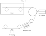
- FIG. 2 is a diagram illustrating a process of fabricating a multi-layered electrode of a secondary battery according to an embodiment of the present invention.
- the method of fabricating a multi-layered electrode according to the present invention may include a primary coating step of applying a binder solution containing magnetic material on a current collector; applying a magnetic field to the current collector to which the binder solution is applied; a secondary coating step of applying an electrode slurry on the first coated binder solution; and a drying step, which may be easily applied to a continuous process and a mass-production process.
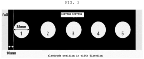
- the present invention also provides a multi-layered electrode including a current collector; and an electrode active material layer containing magnetic material and a binder formed on the current collector, wherein a difference between maximum loading value and a minimum loading value of the electrode active material layer in at least five positions at regular intervals in a width direction is 10% or less of a total average loading value.
- the loading may refer to a weight of the electrode active material layer finally formed after the binder solution and the electrode slurry applied on the electrode current collector are dried, and as a non-limiting example, a specimen may be obtained by punching at least five points at regular intervals in the width direction of the electrode, and the weight of the electrode active material layer of the specimen may be measured.
- the multi-layered electrode according to the present invention may have improved adhesion with respect to the current collector because the solid content is uniformly dispersed in the electrode active material layer.
- the current collector, magnetic material, binder, and electrode active material are the same as described above.
- the multi-layered electrode according to an exemplary embodiment of the present invention may satisfy Relational Expression 2 below. 0.2 ⁇ B 2 / B 1 ⁇ 0.8
- B 1 is the weight of the binder in the entire electrode active material layer
- B 2 is the weight of the binder in a region of 15% of a total thickness of the electrode active material layer from the current collector.
- a content (at%) to an Os element by adsorbing Os gas to the binder may be applied, but this is not limited to the Os element and an element that may indicate a corresponding binder according to types of binders may be used.
- the adhesion of the electrode active material layer with respect to the current collector may be 0.2 N/cm or more, specifically, 0.2 to 1.0 N/cm.
- the multi-layered electrode may satisfy Relational Expression 3 below. ⁇ 30 % ⁇ C ⁇ D / D ⁇ + 30 %
- C is the interfacial adhesion between the current collector and the electrode active material layer measured at a certain position selected in the width direction of the electrode active material layer
- D is an average value of the interfacial adhesion between the current collector and the electrode active material layer.
- C may be measured at positions having a regular interval in the width direction of the electrode active material layer, for example, 0.1 to 0.5 mm, or 0.2 to 0.3 mm, for example 0.25 mm, but the present invention is limited thereto.
- the multi-layered electrode may be a positive electrode.
- the present invention may provide a secondary battery including the multi-layered electrode; a separator; and an electrolyte.
- the multi-layered electrode may be a positive electrode or a negative electrode depending on a type of the electrode active material included in the electrode layer, and the electrode active material is as described above.
- a separator is not particularly limited as long as it is a known separation membrane in the art.
- the separator may be a material selected from among glass fiber, polyester, polyethylene, polypropylene, polytetrafluoroethylene, or a combination thereof, may be in the form of a non-woven fabric or a woven fabric, and may be selectively used in a single-layer or multi-layer structure.
- the electrolyte includes a non-aqueous organic solvent and an electrolyte salt.
- the non-aqueous organic solvent may be ethylene carbonate (EC), propylene carbonate (PC), dimethyl carbonate (DMC), diethyl carbonate (DEC), ethylmethyl carbonate (EMC), 1,2-dimethoxyethane (DME), ⁇ -butyrolactone (BL), tetrahydrofuran (THF), 1,3-dioxolane (DOL), diethyl ether (DEE), methyl formate (MF), methyl propionate (MP), sulfolane (S), dimethyl sulfoxide (DMSO), acetonitrile (AN), or a mixture thereof, but is not limited thereto.
- EC ethylene carbonate
- PC propylene carbonate
- DMC dimethyl carbonate
- DEC diethyl carbonate
- EMC ethylmethyl carbonate
- EMC 1,2-dimethoxyethan
- the electrolyte salt is a material that is dissolved in a non-aqueous organic solvent, serves as a source of electrolytic metal ions in a battery, enables a basic secondary battery operation, and promotes migration of electrolytic metal ions between a positive electrode and a negative electrode.
- the electrolytic salt when the electrolytic metal is lithium, the electrolytic salt may be LiPF 6 , LiBF 4 , LiTFSI, LiSbF 6 , LiAsF 6 , LiClO 4 , LiCF 3 SO 3 , Li(CF 3 SO 2 ) 2 N, LiC 4 F 9 SO 3 , LiSbF 6 , LiAlO 4 , LiAlCl 4 , LiN(C x F 2x+1 SO 2 )(C y F 2y+2 SO 2 )(here, x and y are natural numbers), LiCl, LiI or a mixture thereof, but is not limited thereto.
- the electrolyte salt a known material having a concentration suitable for a purpose may be used, and if necessary, the electrolyte salt may further include a known solvent or additive to improve charge/discharge characteristics, flame retardancy characteristics, and the like.
- a binder solution was prepared by mixing 10 wt% of Ni-coated CNT (Ni content: 3 wt%) and 20 wt% of SBR binder with water at room temperature.
- viscosity of the prepared solid binder solution measured at a shear rate of 1s -1 using a rotational viscometer was 430 cp.
- Ni-coated CNT was prepared by mixing Ni Oxide (Ni(NO 3 ) 2 ⁇ 6H 2 O) with CNT in a 3: 1 weight ratio in distilled water under ultrasonic waves, drying the mixture at 100°C, and then heat-treating a dried mixture at 300°C.
- Ni Oxide Ni(NO 3 ) 2 ⁇ 6H 2 O
- Step 2 Preparation of negative electrode slurry
- a negative electrode slurry (solid content: 50 wt%) was prepared by mixing 95 wt% of artificial graphite, 1.2 wt% of CMC, and 0.5 wt% of SBR.
- the binder solution prepared in step 1 was applied to have a thickness of 5 ⁇ m on one surface of a copper current collector (copper foil having a thickness of 8 ⁇ m) using a slot die coater. Next, by placing neodymium magnets on the upper and lower portions of the current collector, respectively, a unidirectional magnetic field was applied in a direction perpendicular to the current collector under the following conditions.
- the negative electrode slurry prepared in step 2 was applied to the top of the binder solution to have a thickness of 100 um.
- viscosity of the lower binder solution when applying the negative electrode slurry measured at a shear rate of 1s -1 using a rotational viscometer was 1100 cp.
- one surface of the current collector to which the binder solution was applied is referred to as an upper part of the current collector, and the other surface of the current collector to which the binder solution was not applied is referred to as a lower part.
- the copper current collector with the binder solution and the electrode slurry applied thereto was dried for 30 minutes in a drying furnace heated with hot air at 130°C to fabricate a negative electrode having a final thickness of 105 ⁇ m.
- Example 1 without applying a magnetic field to a current collector coated with a binder solution, the current collector coated with the binder solution was dried at 130°C for 1 minute, a negative slurry was applied thereto, and then, the corresponding current collector was subjected to an additional process for 30 minutes to fabricate a negative electrode.
- a negative electrode was fabricated in the same manner as in Example 1, except that a negative electrode slurry was immediately applied without applying a magnetic field to a current collector to which the binder solution was applied.
- Evaluation Example 1 Evaluation of adhesion between negative electrode active material layer and current collector
- the negative electrodes prepared in Example 1 and Comparative Examples 1 and 2 were cut to be 18 mm wide/150 mm long, and 18 mm wide tape was attached to a foil layer of the negative electrode, and then adhered sufficiently with a roller having a load of 2 kg.
- a negative electrode active material layer was attached to one side of the tensile tester using double-sided tape. The tape attached to the foil was fastened to the opposite side of the tensile tester, the adhesion was measured, and results thereof are shown in Table 1 below.
- the negative electrode active material layer refers to an active material layer finally formed after the binder solution and the negative electrode slurry applied on the current collector are dried.
- a 1 is the viscosity of the binder solution before the magnetic field is applied
- a 2 is the viscosity of the binder solution when the negative electrode slurry is applied after the magnetic field is applied.
- Example 1 in the case of Example 1 to which a magnetic field was applied, it can be seen that, when the negative electrode slurry is applied, since the viscosity of the binder solution located at the lower part was high, fluidity of the particles was reduced and a uniform distribution of the binder was maintained, so that the adhesion between the negative electrode active material layer and the current collector is increased.
- a negative electrode was fabricated in the same manner as in Example 1, except that a magnetic field was applied from the top to the bottom of the current collector.
- a negative electrode was fabricated in the same manner as in Example 1, except that the viscosity and magnetic field application conditions of the solid binder solution were set to those described in Table 2 below by varying the solid content during the preparation of the binder solution.
- the solid content of Examples 3 to 5 was adjusted so that the viscosity of each binder solution was 400 to 500 cp.
- a negative electrode was prepared in the same manner as in Example 1, except that a neodymium magnet was placed only on a lower portion of the current collector and a magnetic field was applied in an upward direction of the current collector.
- a 1 is the viscosity of the binder solution before the magnetic field was applied
- a 2 is the viscosity of the binder solution when the negative electrode slurry was applied after the magnetic field was applied.
- the homogeneity of the negative electrode active material layer was high with a similar value, regardless of the magnetic field application direction.
- Example 6 when the magnetic device is located on only one side (lower part) of the current collector (Example 6), it is determined that the magnetic material (or magnetic material-solid particle aggregate) in the lower binder solution were attracted to one side (the lower part of the current collector) to cause a reduction in viscosity due to the reduction in distributed particles in the binder solution, thus exhibiting relatively low homogeneity, compared to Example 1.
- a fast charging evaluation was performed to charge the secondary batteries prepared in Examples 1 to 3 and Comparative Example 2 at a C-rate of 2.5 C at a temperature of 25°C and discharge the secondary batteries prepared in Examples 1 to 3 and Comparative Example 2 at a C-rate of 1/3C. After repeating 100 cycles and 200 cycles, a fast charge capacity retention rate was measured, and results thereof are shown in Table 3 below.
- the present invention may improve interfacial adhesion between the current collector and the electrode active material layer, improve fairness/appearance defects such as electrode detachment, and improve fast charging performance.
Landscapes
- Chemical & Material Sciences (AREA)
- Chemical Kinetics & Catalysis (AREA)
- Electrochemistry (AREA)
- General Chemical & Material Sciences (AREA)
- Engineering & Computer Science (AREA)
- Manufacturing & Machinery (AREA)
- Materials Engineering (AREA)
- Inorganic Chemistry (AREA)
- Battery Electrode And Active Subsutance (AREA)
- Secondary Cells (AREA)
Applications Claiming Priority (2)
| Application Number | Priority Date | Filing Date | Title |
|---|---|---|---|
| KR1020210127849A KR102937028B1 (ko) | 2021-09-28 | 2021-09-28 | 이차전지용 다층 전극 및 이의 제조방법 |
| EP22173385.0A EP4156328A1 (fr) | 2021-09-28 | 2022-05-13 | Électrode multicouche pour batterie et son procédé de fabrication |
Related Parent Applications (1)
| Application Number | Title | Priority Date | Filing Date |
|---|---|---|---|
| EP22173385.0A Division EP4156328A1 (fr) | 2021-09-28 | 2022-05-13 | Électrode multicouche pour batterie et son procédé de fabrication |
Publications (2)
| Publication Number | Publication Date |
|---|---|
| EP4310980A2 true EP4310980A2 (fr) | 2024-01-24 |
| EP4310980A3 EP4310980A3 (fr) | 2024-02-21 |
Family
ID=81653673
Family Applications (2)
| Application Number | Title | Priority Date | Filing Date |
|---|---|---|---|
| EP23215354.4A Pending EP4310980A3 (fr) | 2021-09-28 | 2022-05-13 | Électrode multicouche pour batterie et son procédé de fabrication |
| EP22173385.0A Pending EP4156328A1 (fr) | 2021-09-28 | 2022-05-13 | Électrode multicouche pour batterie et son procédé de fabrication |
Family Applications After (1)
| Application Number | Title | Priority Date | Filing Date |
|---|---|---|---|
| EP22173385.0A Pending EP4156328A1 (fr) | 2021-09-28 | 2022-05-13 | Électrode multicouche pour batterie et son procédé de fabrication |
Country Status (3)
| Country | Link |
|---|---|
| EP (2) | EP4310980A3 (fr) |
| KR (3) | KR102937028B1 (fr) |
| CN (1) | CN115881883A (fr) |
Families Citing this family (2)
| Publication number | Priority date | Publication date | Assignee | Title |
|---|---|---|---|---|
| WO2024259628A1 (fr) * | 2023-06-21 | 2024-12-26 | 广东邦普循环科技有限公司 | Électrode riche en lithium magnétique, procédé de préparation associé et utilisation associée |
| WO2026043295A1 (fr) * | 2024-08-21 | 2026-02-26 | 주식회사 엘지에너지솔루션 | Procédé de fabrication de batterie secondaire et électrode |
Family Cites Families (5)
| Publication number | Priority date | Publication date | Assignee | Title |
|---|---|---|---|---|
| JP2003123742A (ja) * | 2001-10-11 | 2003-04-25 | Mitsubishi Chemicals Corp | 非水電解液二次電池用電極板の製造方法 |
| JP4150516B2 (ja) * | 2001-12-21 | 2008-09-17 | 三星エスディアイ株式会社 | リチウム二次電池の負極用の黒鉛含有組成物の製造方法並びにリチウム二次電池用の負極の製造方法及びリチウム二次電池の製造方法 |
| JP2012174401A (ja) * | 2011-02-18 | 2012-09-10 | Toyota Motor Corp | リチウムイオン二次電池の製造方法 |
| CN104011906B (zh) * | 2011-12-21 | 2016-07-20 | 丰田自动车株式会社 | 锂二次电池 |
| KR102432049B1 (ko) * | 2016-09-30 | 2022-08-16 | 주식회사 엘지에너지솔루션 | 리튬 이차전지용 전극 및 이를 구비한 리튬 이차전지 |
-
2021
- 2021-09-28 KR KR1020210127849A patent/KR102937028B1/ko active Active
-
2022
- 2022-04-13 KR KR1020220045442A patent/KR102946808B1/ko active Active
- 2022-04-21 CN CN202210422048.6A patent/CN115881883A/zh active Pending
- 2022-05-13 EP EP23215354.4A patent/EP4310980A3/fr active Pending
- 2022-05-13 EP EP22173385.0A patent/EP4156328A1/fr active Pending
-
2026
- 2026-03-04 KR KR1020260039158A patent/KR20260045744A/ko active Pending
Also Published As
| Publication number | Publication date |
|---|---|
| KR102946808B1 (ko) | 2026-04-01 |
| KR20230045527A (ko) | 2023-04-04 |
| US20230097017A1 (en) | 2023-03-30 |
| EP4156328A1 (fr) | 2023-03-29 |
| KR20230045245A (ko) | 2023-04-04 |
| CN115881883A (zh) | 2023-03-31 |
| EP4310980A3 (fr) | 2024-02-21 |
| KR20260045744A (ko) | 2026-04-03 |
| KR102937028B1 (ko) | 2026-03-11 |
Similar Documents
| Publication | Publication Date | Title |
|---|---|---|
| KR101460930B1 (ko) | 축전 디바이스용 전극, 전극용 슬러리, 전극용 바인더 조성물 및 축전 디바이스 | |
| KR101620066B1 (ko) | 저저항 전기화학소자용 전극, 그의 제조방법 및 상기 전극을 포함하는 전기화학소자 | |
| KR20200089568A (ko) | 음극 및 이를 포함하는 리튬 이차 전지 | |
| US12176513B2 (en) | Multilayer electrode for secondary battery and fabrication method thereof | |
| JP2026066359A (ja) | 二次電池用負極およびこれを含む二次電池 | |
| KR102928016B1 (ko) | 이차전지용 음극 및 이를 포함하는 이차전지 | |
| CN114597335A (zh) | 一种负极片及包括该负极片的电池 | |
| KR20260045744A (ko) | 이차전지용 다층 전극 및 이의 제조방법 | |
| CN116670850A (zh) | 负极和包含其的二次电池 | |
| EP4084131A1 (fr) | Procédé de fabrication d'anode | |
| KR20220017652A (ko) | 이차전지용 양극의 제조 방법 및 이를 포함하는 이차전지 | |
| JP2026012455A (ja) | 急速充電性能が改善した二次電池用電極、その製造方法およびこれを含む二次電池 | |
| CN114068875A (zh) | 用于二次电池的负极的制造方法及包括负极的二次电池 | |
| CN110190258B (zh) | 硅碳复合材料水性复合浆料及其制备方法、锂离子电池 | |
| KR102863930B1 (ko) | 이차전지용 전극 및 이의 제조방법 | |
| JP2001283862A (ja) | 非水電解質電池 | |
| EP4525067A1 (fr) | Électrode pour batterie secondaire, son procédé de fabrication et batterie secondaire la comprenant | |
| US12620571B2 (en) | Multi-layered electrode for battery and fabrication method thereof | |
| EP4231378A1 (fr) | Anode et batterie secondaire la comprenant | |
| KR20220127615A (ko) | 이차전지용 음극 슬러리의 제조방법 및 이를 포함하는 음극의 제조방법 | |
| EP4372837A1 (fr) | Électrode pour batterie secondaire à performance de charge rapide améliorée, son procédé de fabrication et batterie secondaire la comprenant | |
| EP4207362A2 (fr) | Électrode négative pour batterie secondaire et batterie secondaire la comprenant |
Legal Events
| Date | Code | Title | Description |
|---|---|---|---|
| PUAI | Public reference made under article 153(3) epc to a published international application that has entered the european phase |
Free format text: ORIGINAL CODE: 0009012 |
|
| STAA | Information on the status of an ep patent application or granted ep patent |
Free format text: STATUS: REQUEST FOR EXAMINATION WAS MADE |
|
| REG | Reference to a national code |
Ref country code: DE Ref legal event code: R079 Free format text: PREVIOUS MAIN CLASS: H01M0010058000 Ipc: H01M0004139300 |
|
| PUAL | Search report despatched |
Free format text: ORIGINAL CODE: 0009013 |
|
| 17P | Request for examination filed |
Effective date: 20231212 |
|
| AC | Divisional application: reference to earlier application |
Ref document number: 4156328 Country of ref document: EP Kind code of ref document: P |
|
| AK | Designated contracting states |
Kind code of ref document: A2 Designated state(s): AL AT BE BG CH CY CZ DE DK EE ES FI FR GB GR HR HU IE IS IT LI LT LU LV MC MK MT NL NO PL PT RO RS SE SI SK SM TR |
|
| AK | Designated contracting states |
Kind code of ref document: A3 Designated state(s): AL AT BE BG CH CY CZ DE DK EE ES FI FR GB GR HR HU IE IS IT LI LT LU LV MC MK MT NL NO PL PT RO RS SE SI SK SM TR |
|
| RIC1 | Information provided on ipc code assigned before grant |
Ipc: H01M 10/058 20100101ALI20240115BHEP Ipc: H01M 10/0525 20100101ALI20240115BHEP Ipc: H01M 10/052 20100101ALI20240115BHEP Ipc: H01M 4/587 20100101ALI20240115BHEP Ipc: H01M 4/1393 20100101AFI20240115BHEP |