EP4311019A1 - Ruban isolant, rouleau de gelée, batterie secondaire, bloc-batterie et véhicule - Google Patents
Ruban isolant, rouleau de gelée, batterie secondaire, bloc-batterie et véhicule Download PDFInfo
- Publication number
- EP4311019A1 EP4311019A1 EP22896134.8A EP22896134A EP4311019A1 EP 4311019 A1 EP4311019 A1 EP 4311019A1 EP 22896134 A EP22896134 A EP 22896134A EP 4311019 A1 EP4311019 A1 EP 4311019A1
- Authority
- EP
- European Patent Office
- Prior art keywords
- electrode
- electrode assembly
- insulation tape
- battery
- shape
- Prior art date
- Legal status (The legal status is an assumption and is not a legal conclusion. Google has not performed a legal analysis and makes no representation as to the accuracy of the status listed.)
- Pending
Links
Images







Classifications
-
- H—ELECTRICITY
- H01—ELECTRIC ELEMENTS
- H01M—PROCESSES OR MEANS, e.g. BATTERIES, FOR THE DIRECT CONVERSION OF CHEMICAL ENERGY INTO ELECTRICAL ENERGY
- H01M50/00—Constructional details or processes of manufacture of the non-active parts of electrochemical cells other than fuel cells, e.g. hybrid cells
- H01M50/50—Current conducting connections for cells or batteries
- H01M50/572—Means for preventing undesired use or discharge
- H01M50/584—Means for preventing undesired use or discharge for preventing incorrect connections inside or outside the batteries
- H01M50/59—Means for preventing undesired use or discharge for preventing incorrect connections inside or outside the batteries characterised by the protection means
- H01M50/595—Tapes
-
- H—ELECTRICITY
- H01—ELECTRIC ELEMENTS
- H01M—PROCESSES OR MEANS, e.g. BATTERIES, FOR THE DIRECT CONVERSION OF CHEMICAL ENERGY INTO ELECTRICAL ENERGY
- H01M10/00—Secondary cells; Manufacture thereof
- H01M10/04—Construction or manufacture in general
- H01M10/0431—Cells with wound or folded electrodes
-
- H—ELECTRICITY
- H01—ELECTRIC ELEMENTS
- H01M—PROCESSES OR MEANS, e.g. BATTERIES, FOR THE DIRECT CONVERSION OF CHEMICAL ENERGY INTO ELECTRICAL ENERGY
- H01M10/00—Secondary cells; Manufacture thereof
- H01M10/04—Construction or manufacture in general
- H01M10/0422—Cells or battery with cylindrical casing
-
- H—ELECTRICITY
- H01—ELECTRIC ELEMENTS
- H01M—PROCESSES OR MEANS, e.g. BATTERIES, FOR THE DIRECT CONVERSION OF CHEMICAL ENERGY INTO ELECTRICAL ENERGY
- H01M10/00—Secondary cells; Manufacture thereof
- H01M10/05—Accumulators with non-aqueous electrolyte
- H01M10/058—Construction or manufacture
- H01M10/0587—Construction or manufacture of accumulators having only wound construction elements, i.e. wound positive electrodes, wound negative electrodes and wound separators
-
- H—ELECTRICITY
- H01—ELECTRIC ELEMENTS
- H01M—PROCESSES OR MEANS, e.g. BATTERIES, FOR THE DIRECT CONVERSION OF CHEMICAL ENERGY INTO ELECTRICAL ENERGY
- H01M50/00—Constructional details or processes of manufacture of the non-active parts of electrochemical cells other than fuel cells, e.g. hybrid cells
- H01M50/10—Primary casings; Jackets or wrappings
- H01M50/102—Primary casings; Jackets or wrappings characterised by their shape or physical structure
- H01M50/107—Primary casings; Jackets or wrappings characterised by their shape or physical structure having curved cross-section, e.g. round or elliptic
-
- H—ELECTRICITY
- H01—ELECTRIC ELEMENTS
- H01M—PROCESSES OR MEANS, e.g. BATTERIES, FOR THE DIRECT CONVERSION OF CHEMICAL ENERGY INTO ELECTRICAL ENERGY
- H01M50/00—Constructional details or processes of manufacture of the non-active parts of electrochemical cells other than fuel cells, e.g. hybrid cells
- H01M50/10—Primary casings; Jackets or wrappings
- H01M50/183—Sealing members
- H01M50/186—Sealing members characterised by the disposition of the sealing members
-
- H—ELECTRICITY
- H01—ELECTRIC ELEMENTS
- H01M—PROCESSES OR MEANS, e.g. BATTERIES, FOR THE DIRECT CONVERSION OF CHEMICAL ENERGY INTO ELECTRICAL ENERGY
- H01M50/00—Constructional details or processes of manufacture of the non-active parts of electrochemical cells other than fuel cells, e.g. hybrid cells
- H01M50/20—Mountings; Secondary casings or frames; Racks, modules or packs; Suspension devices; Shock absorbers; Transport or carrying devices; Holders
- H01M50/249—Mountings; Secondary casings or frames; Racks, modules or packs; Suspension devices; Shock absorbers; Transport or carrying devices; Holders specially adapted for aircraft or vehicles, e.g. cars or trains
-
- H—ELECTRICITY
- H01—ELECTRIC ELEMENTS
- H01M—PROCESSES OR MEANS, e.g. BATTERIES, FOR THE DIRECT CONVERSION OF CHEMICAL ENERGY INTO ELECTRICAL ENERGY
- H01M50/00—Constructional details or processes of manufacture of the non-active parts of electrochemical cells other than fuel cells, e.g. hybrid cells
- H01M50/50—Current conducting connections for cells or batteries
- H01M50/531—Electrode connections inside a battery casing
- H01M50/533—Electrode connections inside a battery casing characterised by the shape of the leads or tabs
-
- H—ELECTRICITY
- H01—ELECTRIC ELEMENTS
- H01M—PROCESSES OR MEANS, e.g. BATTERIES, FOR THE DIRECT CONVERSION OF CHEMICAL ENERGY INTO ELECTRICAL ENERGY
- H01M50/00—Constructional details or processes of manufacture of the non-active parts of electrochemical cells other than fuel cells, e.g. hybrid cells
- H01M50/50—Current conducting connections for cells or batteries
- H01M50/543—Terminals
- H01M50/564—Terminals characterised by their manufacturing process
- H01M50/567—Terminals characterised by their manufacturing process by fixing means, e.g. screws, rivets or bolts
-
- H—ELECTRICITY
- H01—ELECTRIC ELEMENTS
- H01M—PROCESSES OR MEANS, e.g. BATTERIES, FOR THE DIRECT CONVERSION OF CHEMICAL ENERGY INTO ELECTRICAL ENERGY
- H01M50/00—Constructional details or processes of manufacture of the non-active parts of electrochemical cells other than fuel cells, e.g. hybrid cells
- H01M50/50—Current conducting connections for cells or batteries
- H01M50/572—Means for preventing undesired use or discharge
- H01M50/584—Means for preventing undesired use or discharge for preventing incorrect connections inside or outside the batteries
- H01M50/586—Means for preventing undesired use or discharge for preventing incorrect connections inside or outside the batteries inside the batteries, e.g. incorrect connections of electrodes
-
- H—ELECTRICITY
- H01—ELECTRIC ELEMENTS
- H01M—PROCESSES OR MEANS, e.g. BATTERIES, FOR THE DIRECT CONVERSION OF CHEMICAL ENERGY INTO ELECTRICAL ENERGY
- H01M50/00—Constructional details or processes of manufacture of the non-active parts of electrochemical cells other than fuel cells, e.g. hybrid cells
- H01M50/50—Current conducting connections for cells or batteries
- H01M50/572—Means for preventing undesired use or discharge
- H01M50/584—Means for preventing undesired use or discharge for preventing incorrect connections inside or outside the batteries
- H01M50/59—Means for preventing undesired use or discharge for preventing incorrect connections inside or outside the batteries characterised by the protection means
- H01M50/593—Spacers; Insulating plates
-
- H—ELECTRICITY
- H01—ELECTRIC ELEMENTS
- H01M—PROCESSES OR MEANS, e.g. BATTERIES, FOR THE DIRECT CONVERSION OF CHEMICAL ENERGY INTO ELECTRICAL ENERGY
- H01M2220/00—Batteries for particular applications
- H01M2220/20—Batteries in motive systems, e.g. vehicle, ship, plane
-
- Y—GENERAL TAGGING OF NEW TECHNOLOGICAL DEVELOPMENTS; GENERAL TAGGING OF CROSS-SECTIONAL TECHNOLOGIES SPANNING OVER SEVERAL SECTIONS OF THE IPC; TECHNICAL SUBJECTS COVERED BY FORMER USPC CROSS-REFERENCE ART COLLECTIONS [XRACs] AND DIGESTS
- Y02—TECHNOLOGIES OR APPLICATIONS FOR MITIGATION OR ADAPTATION AGAINST CLIMATE CHANGE
- Y02E—REDUCTION OF GREENHOUSE GAS [GHG] EMISSIONS, RELATED TO ENERGY GENERATION, TRANSMISSION OR DISTRIBUTION
- Y02E60/00—Enabling technologies; Technologies with a potential or indirect contribution to GHG emissions mitigation
- Y02E60/10—Energy storage using batteries
-
- Y—GENERAL TAGGING OF NEW TECHNOLOGICAL DEVELOPMENTS; GENERAL TAGGING OF CROSS-SECTIONAL TECHNOLOGIES SPANNING OVER SEVERAL SECTIONS OF THE IPC; TECHNICAL SUBJECTS COVERED BY FORMER USPC CROSS-REFERENCE ART COLLECTIONS [XRACs] AND DIGESTS
- Y02—TECHNOLOGIES OR APPLICATIONS FOR MITIGATION OR ADAPTATION AGAINST CLIMATE CHANGE
- Y02P—CLIMATE CHANGE MITIGATION TECHNOLOGIES IN THE PRODUCTION OR PROCESSING OF GOODS
- Y02P70/00—Climate change mitigation technologies in the production process for final industrial or consumer products
- Y02P70/50—Manufacturing or production processes characterised by the final manufactured product
Definitions
- the present invention relates to an insulation tape, a jelly roll, a secondary battery, a battery pack, and a vehicle.
- a secondary battery is easy to apply to product groups and has high electrical characteristics such as high energy density. Therefore, the secondary battery is widely applied not only to portable devices but also to electric vehicles (EVs) or hybrid electric vehicles (HEVs) driven by electrical driving sources.
- EVs electric vehicles
- HEVs hybrid electric vehicles
- the secondary battery attracts attention as a new energy source for improving environmental-friendly characteristics and energy efficiency because the secondary battery achieves a primary advantage of innovatively reducing the use of fossil fuel and does not generate any by-products from the use of energy.
- Types of secondary batteries currently used widely include a lithium-ion battery, a lithium-polymer battery, a nickel-cadmium battery, a nickel-hydrogen battery, a nickel-zinc battery, and the like.
- An operating voltage of a unit secondary battery cell i.e., a unit battery cell is about 2.5 V to 4.5 V. Therefore, when an output voltage higher than the operating voltage is required, a plurality of battery cells is connected in series and constitutes a battery pack. In addition, the plurality of battery cells is connected in parallel and constitutes the battery pack depending on a charge/discharge capacity required for the battery pack. Therefore, the number of battery cells included in the battery pack and the type of electrical connection between the battery cells may be variously set depending on required output voltages and/or charge/discharge capacities.
- An object of the present invention is to provide a jelly roll and a secondary battery that may implement high-energy density.
- Another object of the present invention is to provide an insulation tape for implementing the jelly roll.
- An embodiment of the present invention provides a jelly roll including: an electrode assembly made by winding a stack of a first electrode, a separator, and a second electrode; and an insulation tape configured to cover at least a part of a lateral surface of the electrode assembly and at least a part of an end of the electrode assembly.
- the insulation tape has at least one notching pattern provided in a region that covers at least a part of the end of the electrode assembly.
- an insulation tape i.e., an insulation tape attached to cover at least a part of a lateral surface of an electrode assembly made by winding a stack of a first electrode, a separator, and a second electrode, and cover at least a part of the end of the electrode assembly.
- the insulation tape has at least one notching pattern provided on at least one edge portion.
- Still another embodiment of the present invention provides a secondary battery including the jelly roll according to the above-mentioned embodiment.
- the portions of the insulation tape overlap one another at the end of the electrode assembly perpendicular to the winding axis. For this reason, a stepped portion is formed, which inevitably causes separation between the components positioned at the end of the electrode assembly. The occurrence of the separation may cause a defect of the electrical connection between the electrode tab part and the electrode terminal part.
- the region in which the portions of the insulation tape overlap one another at the end of the electrode assembly is minimized or particularly eliminated. It is possible to prevent a problem of separation in which a space is formed with another component provided at the end of the electrode assembly, for example, a space is formed between the end of the electrode assembly and an additional insulation member or a current collecting plate. Therefore, it is possible to prevent a defect of the electrical connection between the electrode tab part and the electrode terminal part. In addition, it is possible to prevent a welding defect in case that welding is performed to electrically connect the electrode tab part to the electrode terminal part directly or through the current collecting plate.
- the tab structure of the electrode included in the electrode assembly is formed as the non-coated portion of the current collector, on which no electrode active material is not applied, by preventing the separation at the end of the electrode assembly as described above, which makes it possible to increase electric current to be applied to the battery. Therefore, the size of the battery may be increased, the high-energy density may be implemented, and the costs may be reduced.
- An embodiment of the present invention provides a jelly roll including: an electrode assembly made by winding a stack of a first electrode, a separator, and a second electrode; and an insulation tape configured to cover at least a part of a lateral surface of the electrode assembly and at least a part of an end of the electrode assembly.
- the insulation tape has at least one notching pattern provided in a region that covers at least a part of the end of the electrode assembly.
- the notching pattern of the insulation tape means a pattern having a groove portion made by cutting an edge of the insulation tape.
- the end of the electrode assembly means an end of a winding axis of the electrode assembly based on a vertical direction.
- the lateral surface of the electrode assembly means a side of an outer surface of the electrode assembly that is parallel to the winding axis.
- the notching pattern of the insulation tape may minimize a region in which portions of the insulation tape overlap one another in the region that covers at least a part of the end of the electrode assembly. Therefore, the separation is prevented at the end of the electrode assembly, such that the electrode assembly may be compactly packed in a battery can. Furthermore, the separation at the end of the electrode assembly is prevented because of the characteristics of the battery, such that a defect of electrical connection between an electrode tab part and an electrode terminal part may be prevented, resistance may be decreased, and high energy density may be maintained.
- the electrode tab part may be a first electrode tab part or a positive electrode tab part of the electrode assembly, i.e., a first electrode non-coated portion or a positive electrode non-coated portion.
- the electrode terminal part may be a first electrode terminal part or a positive electrode terminal part.
- an area in which the portions of the insulation tape overlap one another is 10% or less of an overall area that covers the end of the electrode assembly.
- the area in which the portions of the insulation tape overlap one another may be 9% or less, 8% or less, or 7% or less of the overall area that covers the end of the electrode assembly. More particularly, the portions of the insulation tape may not overlap one another in the region that covers the end of the electrode assembly.
- FIG. 1 illustrates photographs for comparing, at the end of the electrode assembly, a case (left) in which an insulation tape having no notching pattern is attached and a case (right) in which an insulation tape having a notching pattern is attached.
- a case (left) in which an insulation tape having no notching pattern is attached and a case (right) in which an insulation tape having a notching pattern is attached.
- portions (indicated by circles) in which the portions of the insulation tape overlap one another are observed.
- the portions of the insulation tape overlapping one another are not observed in the right photograph.
- FIG. 2 illustrates photographs for comparing, at a lateral surface of the electrode assembly, a case (left) in which an insulation tape having no notching pattern is attached and a case (right) in which an insulation tape having a notching pattern is attached.
- stepped portions indicated by circles
- no stepped portion made by the overlapping portions of the insulation tape is not observed in the right photograph.
- the insulation tape may have two or more notching patterns.
- a flag shape provided between the two adjacent notching patterns may be at least one of a trapezoidal shape, a quadrangular shape, a parallelogrammatic shape, a triangular shape, and a semi-circular shape.
- the flag shape may be provided in the region in which the insulation tape extends from the lateral surface of the electrode assembly and covers the end of the electrode assembly.
- the flag shapes do not overlap one another at the end of the electrode assembly.
- the flag shape is not limited thereto. Any flag shape may be applied to the present invention as long as the flag shapes do not overlap one another at the end of the electrode assembly.
- a shape of the notching pattern of the insulation tape is at least one of a trapezoidal shape, a quadrangular shape, a parallelogrammatic shape, a triangular shape, and a semi-circular shape.
- the shape of the notching pattern is not limited thereto. Any shape of the notching pattern may be applied to the present invention as long as the portions of the insulation tape do not overlap one another at the end of the electrode assembly.
- FIG. 4 is a view illustrating a shape of the notching pattern of the insulation tape according to the embodiment of the present invention and a state made after the insulation tape is attached.
- FIG. 4 illustrates that the shape 130 of the notching pattern is a triangular shape, the flag shape 140 is a triangular shape, and a shape of the insulation tape provided at the end of the electrode assembly is a triangular shape.
- FIG. 4 illustrates that the shape 130 of the notching pattern is a trapezoidal shape, the flag shape 140 is a trapezoidal shape, and the shape of the insulation tape 120 provided at the end of the electrode assembly is a trapezoidal shape.
- At least one of the first electrode and the second electrode includes a current collector and an electrode active material layer provided on the current collector.
- the current collector includes a non-coated portion on which no electrode active material layer is provided. At least a part of the non-coated portion is exposed to the lateral surface of the electrode assembly, and the insulation tape is provided to cover the non-coated portion on the lateral surface of the electrode assembly.
- At least a part of the non-coated portion provided on the lateral surface of the electrode assembly may be used as an electrode tab as it is.
- the insulation tape is provided to cover the non-coated portion, which makes it possible to prevent electrical contact with the battery can.
- the notching pattern of the insulation tape prevents the separation at the end of the electrode assembly, which makes it possible to prevent a defect of the electrical connection between the electrode tab part and the electrode terminal part.
- the insulation tape is provided to cover 5% to 60% of the first or second electrode exposed to the end of the electrode assembly.
- the non-coated portion is exposed to the end of the electrode assembly, and the insulation tape is provided to cover 5% to 60% of the non-coated portion at the end of the electrode assembly.
- the first or second electrode may be exposed to the end of the electrode assembly. Specifically, at least a part of the non-coated portion of the first or second electrode, on which no electrode active material layer is provided, may be exposed.
- At least a part of the non-coated portion provided at the end of the electrode assembly may be used as an electrode tab as it is.
- a current collecting plate provided at the end of the electrode assembly may be provided, and at least a part of the non-coated portion may be electrically connected to the current collecting plate.
- the non-coated portion of the first or second electrode and/or at least a part of the current collecting plate connected to the non-coated portion may be exposed to the end of the electrode assembly.
- the configuration in which the insulation tape is provided to cover 5% to 60% of the first or second electrode or the non-coated portion of the end of the electrode assembly may mean that the insulation tape covers 5% to 60% of the first or second electrode or the non-coated portion exposed from an outer peripheral surface of the end of the electrode assembly.
- the insulation tape may be provided to cover 5% or more, 100 or more, 15% or more, 20% or more, or 25% or more of the first or second electrode or the non-coated portion of the end of the electrode assembly.
- the insulation tape may be provided to cover 60% or less, 55% or less, 50% or less, 45% or less, 40% or less, or 35% or less of the first or second electrode or the non-coated portion of the end of the electrode assembly.
- the insulation tape is provided to cover 5% to 60% of the first or second electrode, the non-coated portion of the first or second electrode, and/or the current collecting plate connected to the non-coated portion of the end of the electrode assembly, which makes it possible to prevent electrical contact with the battery can.
- the notching pattern of the insulation tape prevents the separation at the end of the electrode assembly, which makes it possible to prevent a defect of the electrical connection between the electrode tab part and the electrode terminal part.
- a thickness of the insulation tape is 10 um to 100 um.
- the thickness of the insulation tape may be 10 um or more, 13 um or more, 15 um or more, or 17 um or more.
- the thickness of the insulation tape may be 100 um or less, 90 um or less, 80 um or less, 70 um or less, 60 um or less, 50 um or less, 40 um or less, or 30 um or less.
- the insulation tape may cover the non-coated portion, which makes it possible to prevent electrical contact with the battery can, prevent the separation at the end of the electrode assembly, and prevent a defect of the electrical connection between the electrode tab part and the electrode terminal part.
- the insulation tape may include a base layer and an adhesive layer.
- a thickness of the base layer is 3 um to 25 um, and a thickness of the adhesive layer is 2 um to 20 um.
- the insulation tape may include the base layer and the adhesive layer.
- a thickness of the insulation tape including the base layer and the adhesive layer may be 15 um or more, 20 um or more, 25 um or more, or 30 um or more.
- the thickness of the insulation tape including the base layer and the adhesive layer may be 90 um or less, 80 um or less, 70 um or less, or 60 um or less.
- a thickness of the base layer of the insulation tape may be 5 um or more, 7 um or more, 9 um or more, or 11 um or more.
- the thickness of the base layer of the insulation tape may be 23 um or less, 21 um or less, 19 um or less, or 17 um or less.
- a thickness of the adhesive layer of the insulation tape may be 4 um or more, 6 um or more, 8 um or more, or 10 um or more.
- the thickness of the adhesive layer of the insulation tape may be 18 um or less, 16 um or less, 14 um or less, or 12 um or less.
- the insulation tape having the notching pattern may be further properly attached to the end of the electrode assembly.
- the insulation tape is advantageous when the thickness of the base layer of the insulation tape is small.
- the insulation tape is more appropriately attached to the end of the electrode assembly as the thickness of the adhesive layer of the insulation tape increases.
- the thickness of the base layer of the insulation tape is decreased by about 50% in comparison with that in the related art.
- the thickness of the adhesive layer is increased by about 150% in comparison with that in the related art.
- the thickness of the base layer of the insulation tape is small, and the thickness of the adhesive layer of the insulation tape is large, such that the insulation tape may be advantageously attached to the end of the electrode assembly.
- the insulation tape includes one or more materials selected from a group consisting of polyimide, polyethylene, polypropylene, polytetrafluoroethylene, polyethylene terephthalate, and polybutylene terephthalate.
- the material of the insulation tape is not particularly limited as long as the material of the insulation tape is an insulating material that is not eluted by an electrolyte or swelled or does not cause a side reaction.
- the current collecting plate provided at the end of the electrode assembly is further included.
- the current collecting plate may be positioned between the insulation tape and the electrode assembly in the region in which the insulation tape covers the end of the electrode assembly.
- the current collecting plate may be positioned at an end opposite to the side of the electrode assembly facing the insulation tape.
- the current collecting plate which is positioned between the insulation tape and the electrode assembly among the current collecting plates provided at the ends of the electrode assembly, may be a first current collecting plate, and the current collecting plate, which is positioned at an end opposite to the side of the electrode assembly facing the insulation tape, may be a second current collecting plate.
- the first current collecting plate may be electrically connected to the non-coated portion, and the side of the first current collecting plate opposite to the non-coated portion may be electrically connected to the electrode terminal.
- the insulation tape having the notching pattern is provided, the separation may be prevented at the end of the electrode assembly, which makes it possible to facilitate the electrical connection of the electrode terminal part and prevent occurrence of a welding defect.
- an insulation member may be further included and provided at the end of the electrode assembly and cover the end of the electrode assembly or cover at least a part of the end of the electrode assembly and at least a part of the lateral surface of the electrode assembly.
- the insulation member may be an insulator.
- the insulator may prevent electrical contact between the electrode tab part of the jelly roll and the battery can, thereby preventing a short circuit of the electrode.
- the region in which the portions of the insulation tape overlap one another at the end of the electrode assembly is minimized, which makes it possible to reduce an interval with the insulation member and prevent a defect of the electrical connection between the electrode tab part and the electrode terminal part.
- FIG. 3 illustrates photographs for comparing a case (left) in which an insulation tape having no notching pattern is attached and a case (right) in which an insulation tape having a notching pattern is attached in terms of whether separation occurs when an additional insulation member is positioned on an upper surface of the electrode assembly.
- the separation of the insulation member is larger in case that the insulation tape having no notching pattern is attached than in case that the insulation tape having the notching pattern is attached.
- FIGS. 7A and 7B are longitudinal sectional views illustrating a schematic configuration of the secondary battery according to the embodiment of the present invention, in which FIG. 7A is a view illustrating a case in which a ' ⁇ '-shaped insulation member is included, and FIG. 7B is a view illustrating a case in which a ' '-shaped insulation member is included.
- an insulation member 60 may be provided to cover at least a part of the end of the electrode assembly and at least a part of the lateral surface of the electrode assembly.
- the insulation member 60 may be a ' ⁇ '-shaped insulation member.
- the insulation member 60 may be provided at the end of the electrode assembly and cover at least a part of the end of the electrode assembly.
- the insulation member 60 may be a '-'-shaped insulation member.
- the insulation tape 100 having the notching pattern is attached in case that the insulation member 60 is included, the region in which the portions of the insulation tape overlap one another at the end of the electrode assembly may be minimized, and the interval with the insulation member 60 may be decreased. Therefore, it is possible to prevent the separation between the electrode tab part and the electrode terminal part and prevent a defect of the electrical connection.
- an insulation tape i.e., an insulation tape attached to cover at least a part of a lateral surface of an electrode assembly, which has a structure made by winding a stack of a first electrode, a separator, and a second electrode, and cover at least a part of the end of the electrode assembly.
- the insulation tape has at least one notching pattern provided on at least one edge portion.
- the insulation tape has two or more notching patterns, a flag shape provided between the two adjacent notching patterns is at least one of a trapezoidal shape, a quadrangular shape, a parallelogrammatic shape, a triangular shape, and a semi-circular shape, and a shape of the notching pattern of the insulation tape is at least one of a trapezoidal shape, a quadrangular shape, a parallelogrammatic shape, a triangular shape, and a semi-circular shape.
- the description of the jelly roll may be applied to the description related to the shape, the thickness, the material, and the structure of the notching pattern of the insulation tape.
- a secondary battery including: a jelly roll according to the above-mentioned embodiment; a battery can configured to accommodate the jelly roll and having an opening portion at one side thereof; an electrode terminal riveted through a through-hole formed in a bottom of the battery can; a gasket provided between an outer diameter of the through-hole and the electrode terminal; and a sealing body configured to seal the opening portion of the battery can.
- the first electrode may be electrically connected to the electrode terminal
- the second electrode may be electrically connected to the battery can
- the sealing body may be insulated from the battery can.
- the description of the jelly roll may be applied to the description related to the shape, the thickness, the material, and the structure of the notching pattern of the insulation tape included in the jelly roll included in the secondary battery.
- the first electrode may be a positive electrode
- the second electrode may be a negative electrode
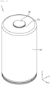
- FIG. 5 is a view illustrating a schematic configuration of the secondary battery according to the embodiment of the present invention
- FIG. 6 is a longitudinal sectional view of the secondary battery in FIG. 5
- FIG. 8 is a view illustrating a schematic configuration of the electrode assembly included in the secondary battery in FIG. 5 .
- a secondary battery 1 includes an electrode assembly 10, a battery can 20, a sealing body 30, and an electrode terminal 40.
- the jelly roll may include the electrode assembly 10.
- the secondary battery 1 may additionally and further include a first current collecting plate 50, the insulation member 60, a gasket 70, a second current collecting plate 80, and/or a sealing gasket 90.
- the electrode assembly 10 includes a first electrode 11, i.e., a positive electrode, a second electrode 12, i.e., a negative electrode, and a separator 13 interposed between the first electrode 11 and the second electrode 12.
- the first electrode 11 and the second electrode 12 may each have a sheet shape.
- the electrode assembly 10 may have a jelly-roll shape. That is, the electrode assembly 10 may be manufactured by winding a stack, which is made by sequentially stacking the first electrode 11, the separator 13, the second electrode 12, and the separator 13 at least once, around a winding center C. In this case, an additional separator 13 may be provided on an outer peripheral surface of the electrode assembly 10 to implement insulation from the battery can 20.
- the first electrode 11 and the second electrode 12 may respectively include non-coated portions 11a and 12a at long side ends thereof, and the non-coated portions 11a and 12a are not coated with the active material layer.
- the first electrode 11 and the second electrode 12 may respectively include coated portions 11b and 12b that are regions coated with the active material layer, except for the non-coated portions 11a and 12a.
- the first electrode 11 includes a first electrode current collector and a first electrode active material applied onto one surface or two opposite surfaces of the first electrode current collector.
- the region in which the first electrode active material is applied onto the first electrode current collector is referred to as the coated portion 11b provided on the first electrode 11.
- the non-coated portion 11a onto which no first electrode active material is applied may be provided at one side end of the first electrode current collector based on a width direction (a direction parallel to a Z-axis). At least a part of the non-coated portion 11a is used as an electrode tab as it is. That is, the non-coated portion 11a serves as the non-coated portion 11a provided on the first electrode 11.
- the non-coated portion 11a provided on the first electrode 11 is provided at an upper side of the electrode assembly 10 based on a height direction (the direction parallel to the Z-axis), and the electrode assembly 10 is accommodated in the battery can 20.
- An additional insulation layer may be provided on a boundary between the non-coated portion 11a and the coated portion 11b of the first electrode 11. The insulation layer may prevent a short circuit of the electrode even though the separator is shrunk.
- the second electrode 12 includes a second electrode current collector and a second electrode active material applied onto one surface or two opposite surfaces of the second electrode current collector.
- the region in which the second electrode active material is applied onto the second electrode current collector is referred to as the coated portion 12b provided on the second electrode 12.
- the non-coated portion 12a onto which no second electrode active material is applied may be provided at the other side end of the second electrode current collector based on the width direction (the direction parallel to the Z-axis). At least a part of the non-coated portion 12a is used as an electrode tab as it is. That is, the non-coated portion 12a serves as the non-coated portion 12a provided on the second electrode 12.
- the non-coated portion 12a provided on the second electrode 12 is provided at a lower side of the electrode assembly 10 based on the height direction (the direction parallel to the Z-axis), and the electrode assembly 10 is accommodated in the battery can 20.
- the non-coated portion 11a provided on the first electrode 11 and the non-coated portion 12a provided on the second electrode 12 may protrude in opposite directions.
- the non-coated portion 11a provided on the first electrode 11 may protrude toward the upper side of the electrode assembly 10 based on the height direction (the direction parallel to the Z-axis)
- the non-coated portion 12a provided on the second electrode 12 may protrude toward the lower side of the electrode assembly 10 based on the height direction (the direction parallel to the Z-axis).
- the non-coated portion 11a provided on the first electrode and the non-coated portion 12a provided on the second electrode may extend and protrude in the opposite directions in the width direction of the electrode assembly 10, i.e., the height direction (the direction parallel to the Z-axis) of the secondary battery 1.
- the first electrode may be a positive electrode
- the second electrode may be a negative electrode
- any active material publicly known in the art may be used, without limitation, as the positive electrode active material applied onto the positive plate and the negative electrode active material applied onto the negative plate.
- a typical positive electrode active material which may be used for a positive electrode of an electrochemical element in the related art, may be used as a non-restrictive example of the positive electrode active material.
- lithium manganese oxide, lithium cobalt oxide, lithium nickel oxide, lithium iron oxide, or a combination thereof, i.e., lithium composite oxide may be used.
- the positive electrode active material may include an alkaline metal compound expressed by a general chemical formula A[A x M y ]O 2+z (A includes one or more elements among Li, Na, and K, M includes one or more elements selected from Ni, Co, Mn, Ca, Mg, Al, Ti, Si, Fe, Mo, V, Zr, Zn, Cu, Al, Mo, Sc, Zr, Ru, and Cr, x ⁇ 0, 1 ⁇ x+y ⁇ 2, and -0.1 ⁇ z ⁇ 2 in which stoichiometric coefficients of materials included in x, y, z, and M are selected so that the compound is kept neutral electrically).
- A includes one or more elements among Li, Na, and K
- M includes one or more elements selected from Ni, Co, Mn, Ca, Mg, Al, Ti, Si, Fe, Mo, V, Zr, Zn, Cu, Al, Mo, Sc, Zr, Ru, and Cr, x ⁇ 0, 1 ⁇ x+y ⁇ 2, and
- the positive electrode active material may be an alkaline metal compound xLiM 1 O 2 -(1-x)Li 2 M 2 O 3 (M 1 includes one or more elements having average oxidation state 3, M 2 includes one or more elements having average oxidation state 4, and 0 ⁇ x ⁇ 1) disclosed in US 6,677,082 , US 6,680,143 , and the like.
- the positive electrode active material may be lithium metal phosphate expressed by a general chemical formula Li a M 1 x Fe 1-x M 2 y P 1-y M 3 z O 4-z
- M 1 includes one or more elements selected from Ti, Si, Mn, Co, Fe, V, Cr, Mo, Ni, Nd, Al, Mg, and Al
- M 2 includes one or more elements selected from Ti, Si, Mn, Co, Fe, V, Cr, Mo, Ni, Nd, Al, Mg, Al, As, Sb, Si, Ge, V, and S
- M 3 includes halogen family elements selectively including F, 0 ⁇ a ⁇ 2, 0 ⁇ x ⁇ 1, 0 ⁇ y ⁇ 1, and 0 ⁇ z ⁇ 1 in which stoichiometric coefficients of materials included in a, x, y, z, M 1 , M 2 , and M 3 are selected so that the compound is kept neutral electrically) or Li 3 M 2 (PO 4 ) 3 (M includes one
- the positive electrode active material may include primary particles and/or secondary particles in which the primary particles are agglomerated.
- a typical negative electrode active material which may be used for a negative electrode of an electrochemical element in the related art, may be used for a non-restrictive example of the negative electrode active material.
- a lithium adsorption material such as lithium metal or lithium alloy, carbon, petroleum coke, activated carbon, graphite, or other carbon may be used.
- carbon materials lithium metal or lithium metal compound, silicon or silicon compound, tin or tin compound, and the like may be used as the negative electrode active material.
- a metal oxide such as TiO 2 and SnO 2 having electric potential of less than 2 V may also be used as the negative electrode active material.
- Low-crystalline carbon, high-crystalline carbon, and the like may be used as the carbon material.
- a porous polymer film for example, a porous polymer film made of polyolefin-based polymer such as ethylene homopolymer, propylene homopolymer, ethylene/butene copolymer, ethylene/hexene copolymer, or ethylene/methacrylate copolymer may be used singly as the separator or a stack of the porous polymer films may be used as the separator.
- a typical porous non-woven fabric for example, a non-woven fabric made of high-melting point fiberglass, polyethylene terephthalate fiber, or the like may be used as the separator.
- At least one surface of the separator may include a coating layer containing inorganic particles.
- the separator itself may be a coating layer containing inorganic particles.
- the particles constituting the coating layer may be coupled by a binder so that an interstitial volume is present between the adjacent particles.
- the inorganic particles may be made of inorganic substance with permittivity of 5 or more.
- the inorganic particle may include one or more materials selected from a group consisting of Pb(Zr,Ti)O 3 (PZT), Pb 1-x La x Zr 1-y Ti y O 3 (PLZT), PB(Mg 3 Nb 2/3 )O 3 -PbTiO 3 (PMN-PT), BaTiO 3 , hafnia(HfO 2 ), SrTiO 3 , TiO 2 , Al 2 O 3 , ZrO 2 , SnO 2 , CeO 2 , MgO, CaO, ZnO, and Y 2 O 3 .
- the electrolyte may be a salt having a structure such as A + B - .
- a + includes ions including alkaline metal cations such as Li + , Na + , and K + , or a combination thereof.
- B - includes one or more anions selected from a group consisting of F - , Cl - , Br - , I - , NO3 - , N(CN) 2- , BF 4 - , ClO 4 - , AlO 4 - , AlCl 4 - , PF 6 - , SbF 6 - , AsF 6 - , BF 2 C 2 O 4 - , BC 4 O 8 - , (CF 3 ) 2 PF 4 - , (CF 3 ) 3 PF 3 - , (CF 3 ) 4 PF 2 - , (CF 3 ) 5 PF - , (CF 3 ) 6 P - , CF 3 SO 3 - , C
- the electrolyte may be dissolved in an organic solvent and used.
- PC Propylene carbonate
- EC ethylene carbonate
- DEC diethyl carbonate
- DMC dimethyl carbonate
- DPC dipropyl carbonate
- dimethyl sulfoxide acetonitrile, dimethoxyethane, diethoxyethane, tetrahydrofuran, N-methyl-2-pyrrolidone (NMP), ethyl methyl carbonate (EMC), ⁇ -butyrolactone, or a mixture thereof
- NMP N-methyl-2-pyrrolidone
- EMC ethyl methyl carbonate
- ⁇ -butyrolactone a mixture thereof
- the battery can 20 is an approximately cylindrical receptacle having an opening portion formed at a lower end thereof.
- the battery can 20 is made of a material such as metal having conductivity.
- a material of the battery can 20 may be aluminum.
- a bottom portion of the battery can 20, where the opening portion is provided, will be referred to as an opened end.
- a lateral surface (outer peripheral surface) of the battery can 20 may be integrated with an upper surface of the battery can 20.
- the upper surface (surface parallel to the X-Y plane) of the battery can 20 has an approximately flat shape.
- the upper surface positioned opposite to the opened end will be referred to as a closed end.
- the battery can 20 accommodates the electrode assembly 10 and an electrolyte through the opening portion formed at the lower side thereof.
- the battery can 20 is electrically connected to the electrode assembly 10.
- the battery can 20 may be electrically connected to one of the first electrode 11 and the second electrode 12.
- the battery can may be electrically connected to the second electrode 12 of the electrode assembly 10.
- the battery can 20 may have the same polarity as the second electrode 12.
- the battery can 20 may have a beading portion 21 and a crimping portion 22 formed at a lower end thereof.
- the beading portion 21 is positioned at a lower side of the electrode assembly 10.
- the beading portion 21 is formed by pressing a periphery of an outer peripheral surface of the battery can 20.
- the beading portion 21 prevents the electrode assembly 10, which has a size approximately corresponding to a width of the battery can 20, from being withdrawn through the opening portion formed at the lower end of the battery can 20.
- the beading portion 21 may serve as a support portion on which the sealing body 30 is seated.
- the crimping portion 22 is formed at a lower side of the beading portion 21.
- the crimping portion 22 has a shape extending and bent to surround a part of an outer peripheral surface of the sealing body 30 disposed at a lower side of the beading portion 21 and surround a part of a lower surface of the sealing body 30.
- the present invention does not exclude a case in which the battery can 20 does not have the beading portion 21 and/or the crimping portion 22. That is, in the present invention, in case that the battery can 20 does not have the beading portion 21 and/or the crimping portion 22, the electrode assembly 10 may be fixed and/or the battery can 20 may be sealed by a component additionally applied and configured to serve as a stopper for the electrode assembly 10, for example. In addition, if the secondary battery 1 of the present invention includes the sealing body 30, the electrode assembly 10 may be fixed and/or the battery can 20 may be sealed by an additionally applied structure, on which the sealing body 30 may be seated, and/or by welding between the battery can 20 and the sealing body 30, for example. That is, the sealing body may seal the opened end of the battery can.
- the sealing body 30 may be made of a metallic material to ensure rigidity, for example.
- the sealing body 30 may cover the opened end formed at the lower end of the battery can 20. That is, the sealing body 30 defines a lower surface of the secondary battery 1.
- the sealing body 30 does not have a polarity even though the sealing body 30 is made of a metallic material having conductivity.
- the configuration in which the sealing body 30 does not have a polarity may mean that the sealing body 30 is electrically insulated from the battery can 20 and the electrode terminal 40.
- the sealing body 30 does not serve as the electrode terminal 40, i.e., a positive electrode terminal or a negative electrode terminal. Therefore, the sealing body 30 need not be electrically connected to the electrode assembly 10 and the battery can 20, and the material of the sealing body 30 need not necessarily be conductive metal.
- the sealing body 30 may be seated on the beading portion 21 formed on the battery can 20.
- the sealing body 30 may be fixed by the crimping portion 22.
- a sealing gasket 90 may be interposed between the sealing body 30 and the crimping portion 22 of the battery can 20 to ensure sealability of the battery can 20.
- the battery can 20 of the present invention may not have the beading portion 21 and/or the crimping portion 22.
- the sealing gasket 90 may be interposed between the sealing body 30 and a fixing structure provided at the opening portion of the battery can 20 to ensure sealability of the battery can 20.
- the electrode terminal 40 may be electrically connected to the other of the first electrode 11 and the second electrode 12. That is, the electrode terminal 40 may have the opposite polarity to the battery can 20.
- the electrode terminal 40 may be electrically connected to the first electrode 11 of the electrode assembly 10. Further, a surface of the electrode terminal 40 may be exposed to the outside.
- the electrode terminal 40 may be made of a metallic material having conductivity.
- the electrode terminal 40 may penetrate an approximately central portion of the closed end formed at the upper end of the battery can 20. A part of the electrode terminal 40 may be exposed to an upper side of the battery can 20, and the remaining part of the electrode terminal 40 may be positioned in the battery can 20.
- the electrode terminal 40 may be fixed onto an inner surface of the closed end of the battery can 20 by riveting.
- the electrode terminal 40 may penetrate the insulation member 60 and be coupled to the non-coated portion 11a provided on the first electrode 11 or the first current collecting plate 50. In this case, the electrode terminal 40 may have a first polarity.
- the electrode terminal 40 may serve as a first electrode terminal in the secondary battery 1 of the present invention.
- the electrode terminal 40 has the first polarity as described above, the electrode terminal 40 is electrically insulated from the battery can 20 having a second polarity.
- the electrical insulation between the electrode terminal 40 and the battery can 20 may be implemented in various ways.
- the insulation tape is provided to cover at least a part of the non-coated portion 11a provided on the first electrode 11 or the first current collecting plate 50, which makes it possible to prevent the electrical contact with the battery can.
- the notching pattern of the insulation tape prevents the separation at the end of the electrode assembly, which makes it possible to prevent a defect of the electrical connection between the non-coated portion 11a and the electrode terminal 40 provided on the first current collecting plate 50 or the first electrode 11.
- the tab structure of the electrode included in the electrode assembly is formed as the non-coated portion by preventing the separation at the end of the electrode assembly as described above, which makes it possible to increase electric current to be applied to the battery. Therefore, the size of the battery may be increased, the high-energy density may be implemented, and the costs may be reduced.
- the insulation may be implemented by interposing the gasket 70, which will be described below, between the electrode terminal 40 and the battery can 20.
- the insulation may be implemented by forming an insulating coating layer on a part of the electrode terminal 40.
- the electrode terminal 40 may be structurally securely fixed so that the electrode terminal 40 and the battery can 20 cannot come into contact with each other.
- a plurality of methods among the above-mentioned methods, may be applied.
- the first current collecting plate 50 may be coupled to the upper portion of the electrode assembly 10.
- the first current collecting plate 50 may be coupled to the non-coated portion 11a provided on the first electrode 11 on the upper portion of the electrode assembly 10.
- the first current collecting plate 50 may be made of a metallic material having conductivity.
- the first current collecting plate 50 may have a plurality of concave-convex portions radially formed on a lower surface of the first current collecting plate 50.
- the first current collecting plate 50 may be pushed to press the concave-convex portions into the non-coated portion 11a provided on the first electrode 11.
- the secondary battery 1 according to another embodiment of the present invention may not include the first current collecting plate 50.
- the non-coated portion 11a provided on the first electrode 11 may be electrically connected directly to the electrode terminal 40.
- the first current collecting plate 50 may be coupled to the end of the non-coated portion 11a provided on the first electrode 11.
- the non-coated portion 11a provided on the first electrode 11 and the first current collecting plate 50 may be coupled to each other by laser welding.
- the laser welding may be performed by partially melting a base material of the first current collecting plate 50.
- the laser welding may be performed in a state in which welding solder is interposed between the first current collecting plate 50 and the non-coated portion 11a. In this case, the solder may have a lower melting point than the first current collecting plate 50 and the non-coated portion 11a.
- resistance welding, ultrasonic welding, and the like may be applied in addition to the laser welding, but the welding method is not limited thereto.
- FIG. 9 is a view illustrating a schematic configuration of an electrode assembly according to another embodiment of the present invention.
- the first current collecting plate 50 may be coupled to a coupling surface formed by bending the end of the non-coated portion 11a, which is provided on the first electrode 11, in the direction parallel to the first current collecting plate 50.
- the bending direction of the non-coated portion 11a may be a direction toward the winding center C of the electrode assembly 10.
- a space occupied by the non-coated portion 11a is decreased, which makes it possible to improve energy density.
- a coupling area between the non-coated portion 11a and the first current collecting plate 50 increases, which makes it possible to increase a coupling force and reduce resistance.
- the insulation member 60 may be provided between an upper end of the electrode assembly 10 and an inner surface of the battery can 20, between the inner surface of the battery can 20 and the first current collecting plate 50 coupled to the upper portion of the electrode assembly 10, or between the inner surface of the battery can 20 and the insulation tape 100 provided on the upper portion of the electrode assembly 10.
- the insulation member 60 prevents the contact between the battery can 20 and the non-coated portion 11a provided on the first electrode 11, the contact between the first current collecting plate 50 and the battery can 20, and/or the contact between the insulation tape 100 and the battery can 20. That is, the insulation member 60 is accommodated in the battery can 20 and configured to block the electrical connection between the battery can 20 and the non-coated portion 11a provided on the first electrode 11. Therefore, the insulation member 60 may be made of a material having insulation performance.
- the insulation member 60 may include a polymer material.
- the insulation member 60 may include a ' ⁇ '-shaped insulation member or a '-'-shaped insulation member.
- the gasket 70 is interposed between the battery can 20 and the electrode terminal 40 and prevents the battery can 20 and the electrode terminal 40, which have the opposite polarities, from coming into contact with each other. That is, the gasket 70 blocks the electrical connection between the battery can 20 and the electrode terminal 40. Therefore, the upper surface of the battery can 20, which has an approximately flat shape, may serve as a terminal of the second electrode 12 of the secondary battery 1.
- the second current collecting plate 80 may be coupled to a lower portion of the electrode assembly 10.
- the second current collecting plate 80 may be made of a metallic material having conductivity.
- the second current collecting plate 80 may be connected to the non-coated portion 12a provided on the second electrode 12.
- the second current collecting plate 80 may be electrically connected to the battery can 20.
- the second current collecting plate 80 may be interposed and fixed between the inner surface of the battery can 20 and the sealing gasket 90.
- the second current collecting plate 80 may be welded to an inner wall surface of the battery can 20.
- the second current collecting plate 80 may have a plurality of concave-convex portions radially formed on one surface of the second current collecting plate 80. In case that the concave-convex portions are formed, the second current collecting plate 80 may be pushed to press the concave-convex portions into the non-coated portion 12a provided on the second electrode 12.
- the second current collecting plate 80 may be coupled to the end of the non-coated portion 12a provided on the second electrode 12.
- the non-coated portion 12a provided on the second electrode 12 and the second current collecting plate 80 may be coupled to each other by laser welding.
- the laser welding may be performed by partially melting a base material of the second current collecting plate 80.
- the laser welding may be performed in a state in which welding solder is interposed between the second current collecting plate 80 and the non-coated portion 12a. In this case, the solder may have a lower melting point than the second current collecting plate 80 and the non-coated portion 12a.
- resistance welding, ultrasonic welding, and the like may be applied in addition to the laser welding, but the welding method is not limited thereto.
- the second current collecting plate 80 may be coupled to a coupling surface formed by bending the end of the non-coated portion 12a, which is provided on the second electrode 12, in the direction parallel to the second current collecting plate 80.
- the bending direction of the non-coated portion 12a provided on the second electrode 12 may be a direction toward the winding center C of the electrode assembly 10.
- a space occupied by the non-coated portion 12a is decreased, which makes it possible to improve energy density.
- a coupling area between the non-coated portion 12a and the second current collecting plate 80 increases, which makes it possible to increase a coupling force and reduce resistance.
- the electrode assembly 10 according to the embodiment in FIG. 9 is similar to the electrode assembly 10 of the embodiment in FIG. 8 , a repeated description of the components substantially identical or similar to the components in the previous embodiment will be omitted. Hereinafter, the description will be focused on a difference from the previous embodiment.
- the electrode assembly 10 may have a structure in which the non-coated portions 11a and 12a are at least partially bent toward a core.
- the non-coated portions 11a and 12a may be divided into a plurality of segmental pieces.
- the plurality of segmental pieces may be structured to overlap one another in multiple layers while being bent toward the core.
- the plurality of segmental pieces may be notched by a laser.
- the segmental piece may be formed by a publicly-known metal foil cutting process such as ultrasonic cutting or blanking.
- an area of the first or second electrode 11 or 12, which is exposed to the end of the electrode assembly, or an area of each of the non-coated portions 11a and 12a of the electrode may be made by subtracting an area of a mandrel part from an overall area of the end of the electrode assembly.
- a predetermined gap may be provided between the active material layer and a lower end of a cutting line between the segmental pieces in order to prevent damage to the active material layer and/or the insulation layer when the bending processing is performed on the non-coated portions 11a and 12a. This is because stress is concentrated on a portion in the vicinity of the lower end of the cutting line when the non-coated portions 11a and 12a are bent.
- the gap may be 0.2 to 4 mm. When the gap is adjusted to the corresponding numerical value, it is possible to prevent damage to the active material layer in the vicinity of the lower end of the cutting line by stress that occurs when the bending processing is performed on the non-coated portions 11a and 12a. In addition, the gap may prevent damage to the active material layer caused by tolerance at the time of notching or cutting the segmental piece.
- the bending directions of the non-coated portions 11a and 12a may be the directions toward the winding center C of the electrode assembly 10.
- the spaces occupied by the non-coated portions 11a and 12a are decreased, which makes it possible to improve energy density.
- the coupling areas between the non-coated portions 11a and 12a and the current collecting plates 50 and 80 increase, which makes it possible to increase a coupling force and reduce resistance. Therefore, it is possible to increase electric current applied to the battery. Therefore, the size of the battery may be increased, the high-energy density may be implemented, and the costs may be reduced.
- the secondary battery is a cylindrical secondary battery.
- the secondary battery may include the battery can that accommodates the jelly roll.
- the battery can may have a cylindrical shape.
- a diameter of a circle of each of the two opposite ends of the battery can may be 30 mm to 55 mm, and a height of the battery can may be 60 mm to 120 mm.
- a value of circular diameter x height of the cylindrical battery can may be 40 mm x 60 mm, 40 mm x 80 mm, 40 mm x 90 mm, or 40 mm x 120 mm.
- the secondary battery may be a battery cell.
- the cylindrical battery cell may be a cylindrical battery cell having a ratio of a form factor larger than about 0.4 (a ratio of the form factor is defined as a value made by dividing a diameter of the cylindrical battery cell by a height of the cylindrical battery cell, i.e., a ratio of a diameter ⁇ to a height H).
- the form factor means a value indicating the diameter and the height of the cylindrical battery cell.
- the cylindrical battery cell according to the embodiment of the present invention may be 46110 cell, 48750 cell, 48110 cell, 48800 cell, 46800 cell, and 46900 cell.
- the first two numbers indicate a diameter of the cell
- the next two numbers indicate a height of the cell
- the final number 0 indicates that a cross-section of the cell is circular.
- the battery cell according to the embodiment of the present invention is an approximately cylindrical cell, and the battery cell may have a diameter of about 46 mm, a height of about 110 mm, and a ratio of the form factor of 0.418.
- the battery cell according to another embodiment of the present invention is an approximately cylindrical cell, and the battery cell may have a diameter of about 48 mm, a height of about 75 mm, and a ratio of the form factor of 0.640.
- the battery cell according to still another embodiment of the present invention is an approximately cylindrical cell, and the battery cell may have a diameter of about 48 mm, a height of about 110 mm, and a ratio of the form factor of 0.418.
- the battery cell according to yet another embodiment of the present invention is an approximately cylindrical cell, and the battery cell may have a diameter of about 48 mm, a height of about 80 mm, and a ratio of the form factor of 0.600.
- the battery cell according to still yet another embodiment of the present invention is an approximately cylindrical cell, and the battery cell may have a diameter of about 46 mm, a height of about 80 mm, and a ratio of the form factor of 0.575.
- the battery cell according to another further embodiment of the present invention is an approximately cylindrical cell, and the battery cell may have a diameter of about 46 mm, a height of about 90 mm, and a ratio of the form factor of 0.511.
- battery cells having the ratio of the form factor of approximately 0.4 or less are used. That is, in the related art, 18650 cell, 21700 cell, and the like are used, for example.
- 18650 cell a diameter thereof is about 18 mm
- a height thereof is about 65 mm
- a ratio of the form factor thereof is 0.277.
- 21700 cell a diameter thereof is about 21 mm
- a height thereof is about 70 mm
- a ratio of the form factor thereof is 0.300.
- Still yet another embodiment of the present invention provides a battery module and a battery pack that include the secondary battery according to the above-mentioned embodiment.
- the secondary battery according to the above-mentioned embodiment may be used to manufacture the battery pack.
- FIG. 15 is a view illustrating a schematic configuration of a battery pack including the secondary battery in FIG. 6 .
- a battery pack 3 according to an embodiment of the present invention includes an assembly to which the secondary battery 1 is electrically connected, and a pack housing 2 configured to accommodate the assembly.
- the secondary battery 1 is the battery cell according to the above-mentioned embodiment.
- components such as busbars for electrical connection between the cylindrical secondary batteries 1, a cooling unit, and an external terminal are omitted from the drawings.
- the battery pack 3 may be mounted on a vehicle.
- the vehicle may be an electric vehicle, a hybrid vehicle, or a plug-in hybrid vehicle.
- the vehicle may be a four-wheel vehicle or a two-wheel vehicle.
- FIG. 16 is a view illustrating a schematic configuration of a vehicle including the battery pack in FIG. 15 .
- a vehicle 5 according to an embodiment of the present invention includes the battery pack 3 according to the embodiment of the present invention.
- the vehicle 5 operates by receiving electric power from the battery pack 3 according to the embodiment of the present invention.
- An electrode assembly was manufactured by sequentially stacking and winding a negative electrode (a negative electrode current collector: Cu foil, and a negative electrode active material: 50 parts by weight of artificial graphite and 50 parts by weight of natural graphite), a sheet-shaped polyethylene separator, a positive electrode (positive electrode current collector: Al foil, and an active material: LiCoO2), and the polyethylene separator.
- a diameter of the end of the electrode assembly perpendicular to the winding axis was 45 mm.
- An insulation tape made of a polyimide material and having a notching pattern (a notching pattern shape: trapezoidal, and a flag shape: triangular) was attached to the lateral surface of the electrode assembly and the end of the electrode assembly to cover the exposed positive electrode non-coated portion.
- the insulation tape which had a notching pattern, a length of 7 mm, and a thickness of 17.5 um (a base layer: 12.5 um, and an adhesive layer: 5 ⁇ m), and included the portions for covering the lateral surface of the electrode assembly and the end of the electrode assembly, was used.
- the parts of the insulation tape did not overlap one another in the region that covered the end of the electrode assembly.
- An area of the insulation tape, which covered the end of the electrode assembly, was calculated on the basis of Experimental Example 1 to be described below.
- the insulation tape covered about 26. 7% of the positive electrode non-coated portion of end of the electrode assembly.
- a jelly roll was manufactured to include an insulation member (a ' ⁇ '-shaped insulation member) disposed at the end of the electrode assembly to which the insulation tape was attached, and the insulation member covered a part of the lateral surface and the end of the electrode assembly.
- a secondary battery was manufactured by inserting the manufactured jelly roll into a battery can (a diameter: 45 mm to 47 mm, and a material: steel) having an opening portion at one side thereof, injecting an electrolyte, which is made by mixing ethylene carbonate (EC) and ethyl methyl carbonate (EMC) at a volume ratio of 30:70 and dissolving the mixture so that molarity of LiPF6 is 1.0 M, and then sealing the cylindrical battery can with a sealing body.
- an electrolyte which is made by mixing ethylene carbonate (EC) and ethyl methyl carbonate (EMC) at a volume ratio of 30:70 and dissolving the mixture so that molarity of LiPF6 is 1.0 M
- a riveting structure of the electrode terminal was manufactured by riveting an electrode terminal through a through-hole formed in a bottom of the battery can, and providing a gasket between the electrode terminal and an outer diameter portion of the through-hole.
- the battery can and the negative electrode of the jelly roll were electrically connected to each other, the positive electrode and the electrode terminal were electrically connected to each other, and the sealing body was insulated from the battery can.
- a jelly roll and a secondary battery were manufactured by the same method as those in Example 1, except that an insulation tape having a notching pattern and a thickness of 22.5 um (a base layer: 12.5 um, and an adhesive layer: 10 ⁇ m) was attached.
- a jelly roll and a secondary battery were manufactured by the same method as those in Example 1, except that an insulation tape having no notching pattern and a thickness of 30 um (a base layer: 25 um, and an adhesive layer: 5 ⁇ m) was attached to cover at least a part of the end of the electrode assembly and the lateral surface of the electrode assembly.
- a jelly roll and a secondary battery were manufactured by the same method as those in Comparative Example 1, except that an insulation tape having no notching pattern and a thickness of 17.5 ⁇ m (a base layer: 12.5 um, and an adhesive layer: 5 ⁇ m) was attached.
- a jelly roll and a secondary battery were manufactured by the same method as those in Comparative Example 1, except that an insulation tape having no notching pattern and a thickness of 22.5 um (a base layer: 12.5 um, and an adhesive layer: 10 ⁇ m) was attached.
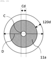
- FIG. 10 is a view illustrating the end of the electrode assembly to calculate the area of the insulation tape that covers the end of the electrode assembly.
- the area of the insulation tape, which covers the first or second electrode or the non-coated portion 11a of the electrode exposed to the end of the electrode assembly was calculated as follows.
- a diameter D of the end perpendicular to the winding axis of the electrode assembly, a length 120d of a portion of the insulation tape that covers the end of the electrode assembly, and a diameter Cd of the mandrel part are as follows.
- the area, which covers the end of the electrode assembly was calculated as follows.
- a bonding layer of the insulation tape was compressed on a SUS304 substrate by reciprocating a rubber roller of 2 kg once, the bonding layer was left unattended for 20 minutes at 23°C, and then the adhesive force of the insulation tape was measured by using a texture analyzer (Stable Micro Systems) at a separation speed of 300 mm/min at an angle of 180° on a backplate film from colored polyimide.
- a texture analyzer Stable Micro Systems
- a height of the insulation tape, which is separated from the end of the electrode assembly was measured.
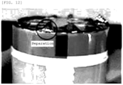
- Table 1 below, o indicates a case in which the height of the insulation tape separated from the end of the electrode assembly of the jelly roll is 2 mm or more, ⁇ indicates a case in which the height of the insulation tape separated from the end of the electrode assembly of the jelly roll is 1 mm to 2 mm, and X indicates a case in which the height of the insulation tape separated from the end of the electrode assembly of the jelly roll is 1 mm or less.
- the identification of the separation in Example 1 is illustrated in FIG. 11
- the identification of the separation in Comparative Example 1 is illustrated in FIG. 12
- the identification of the separation in Comparative Example 3 is illustrated in FIG. 13 .
- the identification of the separation in Example 2 may be as illustrated in FIG. 11 because a degree of separation is not recognized with the naked eye in comparison with that in Example 1.
- the identification of the separation in Comparative Example 2 may be as illustrated in FIG. 12 because a degree of separation is not recognized with the naked eye in comparison with that in Comparative Example 1.
- Examples 1 and 2 include the insulation tape having the notching pattern according to the present invention. It can be ascertained that the amount of separation is small at the end of the electrode assembly of the jelly roll in comparison with Comparative Examples 1 to 3 that include the insulation tape having no notching pattern. Therefore, Examples 1 and 2 may prevent the separation at the end of the electrode assembly, which makes it possible to prevent a defect of the electrical connection between the electrode tab part and the electrode terminal part, in comparison with Comparative Examples 1 to 3.
- Examples 1 and 2 are different from each other in terms of a thickness of the insulation tape, particularly, a thickness of the adhesive layer. It can be ascertained that the thickness of the adhesive layer in Example 2 is larger than twice the thickness of the adhesive layer in Example 1, and the adhesive layer in Example 2 has a high adhesive force and causes a small amount of separation at the end of the electrode assembly.
- Comparative Examples 1 and 2 are different from each other in terms of a thickness of the insulation tape, particularly, a thickness of a base layer. It can be ascertained that the thickness of the base layer in Comparative Example 2 is 1/2 times the thickness of the base layer in Comparative Example 1, and the degree of separation is improved even though the adhesive force is low. Therefore, it can be ascertained that the use of the insulation tape, in which the thickness of the adhesive layer is larger than the thickness of the base layer, improves the degree of separation.
- Example 1 and Comparative Example 2 are different and Example 2 and Comparative Example 3 are different only in terms of whether the notching is present even though the thicknesses of the base layer and the adhesive layer of the insulation tape are equal to each other. It can be ascertained that the separation at the end of the electrode assembly is improved in Examples 1 and 2 having the notching in comparison with Comparative Examples 2 and 3 even though the thicknesses of the base layer and the adhesive layer of the insulation tape are equal to each other. Therefore, it is possible to prevent a defect of the electrical connection between the electrode tab part and the electrode terminal part.
- the insulation tape having the notching pattern may be further properly attached to the end of the electrode assembly.
- the insulation tape is advantageous when the thickness of the base layer of the insulation tape is small.
- the insulation tape is more appropriately attached to the end of the electrode assembly as the thickness of the adhesive layer of the insulation tape increases.
- the thickness of the base layer of the insulation tape is decreased by about 50% and the thickness of the adhesive layer is increased by about 150% in Example 1 in comparison with Comparative Example 1. That is, it can be ascertained that in Example 1, the thickness of the base layer of the insulation tape is decreased, and the thickness of the adhesive layer of the insulation tape is increased, such that the insulation tape is advantageously attached to the end of the electrode assembly.
- the AC resistance of the secondary battery was measured by using a battery tester (battery tester BT3554-51 of HIOKI) under a room temperature condition. The measurement was performed by bringing two leads of the battery tester into contact with the positive electrode terminal part (riveted electrode terminal) and the negative electrode terminal part (battery can).
- the measurement of the AC resistance of the secondary battery is performed to measure internal resistance by using an alternating current method, i.e., a method that measures resistance of the battery by applying a micro-alternating current signal to the battery. It is possible to indirectly identify a defect of the electrical connection between the electrode tab part and the electrode terminal part by measuring the AC resistance.
- Example 1 includes the insulation tape according to the present invention that has the notching pattern and the comparatively small thickness. It can be ascertained that Example 1 has a lower AC resistance value than Comparative Example 1 including the insulation tape having a comparatively large thickness without having a notching pattern.
- Comparative Examples 1 and 2 are different from each other in terms of a thickness of the insulation tape, particularly, a thickness of a base layer. It can be ascertained that the thickness of the base layer in Comparative Example 2 is 1/2 times the thickness of the base layer in Comparative Example 1, and the AC resistance is improved even though the adhesive force is low. Therefore, it can be ascertained that the use of the insulation tape, in which the thickness of the adhesive layer is larger than the thickness of the base layer, improves the AC resistance.
- Comparative Examples 2 and 3 include the insulation tape having no notching pattern even though the thicknesses of the base layer and the adhesive layer of the insulation tape are equal to each other in Comparative Examples 2 and 3 and Examples 1 and 2, it can be ascertained that the AC resistance value is higher in Comparative Examples 2 and 3 than in Examples 1 and 2.
- the notching pattern of the insulation tape may minimize the region in which the portions of the insulation tape overlap one another at the end of the electrode assembly, and prevent the separation at the end of the electrode assembly, which makes it possible to prevent a defect of the electrical connection between the electrode tab part and the electrode terminal part. It can be ascertained that the insulation tape, which has a large thickness, particularly, a large thickness of the adhesive layer, is advantageously attached to the end of the electrode assembly.
Landscapes
- Chemical & Material Sciences (AREA)
- Chemical Kinetics & Catalysis (AREA)
- Electrochemistry (AREA)
- General Chemical & Material Sciences (AREA)
- Engineering & Computer Science (AREA)
- Manufacturing & Machinery (AREA)
- Aviation & Aerospace Engineering (AREA)
- Secondary Cells (AREA)
- Battery Mounting, Suspending (AREA)
- Connection Of Batteries Or Terminals (AREA)
- Sealing Battery Cases Or Jackets (AREA)
Applications Claiming Priority (2)
| Application Number | Priority Date | Filing Date | Title |
|---|---|---|---|
| KR20210160779 | 2021-11-19 | ||
| PCT/KR2022/018310 WO2023090937A1 (fr) | 2021-11-19 | 2022-11-18 | Ruban isolant, rouleau de gelée, batterie secondaire, bloc-batterie et véhicule |
Publications (2)
| Publication Number | Publication Date |
|---|---|
| EP4311019A1 true EP4311019A1 (fr) | 2024-01-24 |
| EP4311019A4 EP4311019A4 (fr) | 2025-04-23 |
Family
ID=89432573
Family Applications (1)
| Application Number | Title | Priority Date | Filing Date |
|---|---|---|---|
| EP22896134.8A Pending EP4311019A4 (fr) | 2021-11-19 | 2022-11-18 | Ruban isolant, rouleau de gelée, batterie secondaire, bloc-batterie et véhicule |
Country Status (4)
| Country | Link |
|---|---|
| US (1) | US20240291014A1 (fr) |
| EP (1) | EP4311019A4 (fr) |
| JP (1) | JP7695049B2 (fr) |
| CA (1) | CA3238477A1 (fr) |
Families Citing this family (4)
| Publication number | Priority date | Publication date | Assignee | Title |
|---|---|---|---|---|
| KR20240076284A (ko) * | 2022-11-23 | 2024-05-30 | 삼성에스디아이 주식회사 | 버튼 전지 |
| KR20250153606A (ko) * | 2024-04-18 | 2025-10-27 | 삼성에스디아이 주식회사 | 전극 조립체 및 이를 구비한 이차 전지 |
| WO2025225437A1 (fr) * | 2024-04-23 | 2025-10-30 | パナソニックIpマネジメント株式会社 | Batterie secondaire à électrolyte non aqueux |
| KR20260038000A (ko) * | 2024-09-11 | 2026-03-18 | 삼성에스디아이 주식회사 | 이차전지용 테이프 부착 장치, 방법 및 시스템 |
Family Cites Families (6)
| Publication number | Priority date | Publication date | Assignee | Title |
|---|---|---|---|---|
| US8236441B2 (en) | 2007-07-24 | 2012-08-07 | A123 Systems, Inc. | Battery cell design and methods of its construction |
| JP5439317B2 (ja) * | 2010-08-30 | 2014-03-12 | 日立ビークルエナジー株式会社 | 二次電池 |
| JP5590410B2 (ja) | 2011-02-10 | 2014-09-17 | 日立オートモティブシステムズ株式会社 | 円筒形二次電池 |
| KR20150022214A (ko) * | 2013-08-22 | 2015-03-04 | 삼성에스디아이 주식회사 | 파우치형 이차 전지 |
| JP2020013729A (ja) | 2018-07-19 | 2020-01-23 | トヨタ自動車株式会社 | 直列積層型全固体電池の製造方法 |
| WO2021020235A1 (fr) * | 2019-07-30 | 2021-02-04 | 株式会社村田製作所 | Batterie secondaire, bloc-batterie, outil électrique, aéronef électrique et véhicule électrique |
-
2022
- 2022-11-18 EP EP22896134.8A patent/EP4311019A4/fr active Pending
- 2022-11-18 CA CA3238477A patent/CA3238477A1/fr active Pending
- 2022-11-18 US US18/290,034 patent/US20240291014A1/en active Pending
- 2022-11-18 JP JP2023565413A patent/JP7695049B2/ja active Active
Also Published As
| Publication number | Publication date |
|---|---|
| JP2024515956A (ja) | 2024-04-11 |
| EP4311019A4 (fr) | 2025-04-23 |
| US20240291014A1 (en) | 2024-08-29 |
| CA3238477A1 (fr) | 2023-05-25 |
| JP7695049B2 (ja) | 2025-06-18 |
Similar Documents
| Publication | Publication Date | Title |
|---|---|---|
| EP4199206B1 (fr) | Structure de rivetage de borne d'électrode, et batterie secondaire, bloc-batterie et automobile la comprenant | |
| EP4047725B1 (fr) | Batterie, et bloc-batterie et véhicule la comprenant | |
| US20230130340A1 (en) | Riveting structure of electrode terminal, and cylindrical battery cell, battery pack and vehicle including the same | |
| CN217740661U (zh) | 电池以及包括该电池的电池组和车辆 | |
| US20240128605A1 (en) | Electrode assembly, battery, and battery pack and vehicle including the same | |
| US20240291014A1 (en) | Insulation tape, jelly roll, secondary battery, battery pack, and vehicle | |
| EP4329026A1 (fr) | Ensemble électrode, élément de batterie cylindrique, et batterie et véhicule la comprenant | |
| EP4145576A2 (fr) | Ensemble électrodes et son procédé de fabrication, cellule de batterie cylindrique comprenant l'ensemble électrodes, et bloc-batterie et automobile comprenant une cellule de batterie cylindrique | |
| EP4297172A1 (fr) | Batterie secondaire, et bloc-batterie et véhicule le comportant | |
| CN115911584A (zh) | 圆柱形电池单元、电池组和包括其的车辆,及其制造方法 | |
| US20240014521A1 (en) | Secondary battery, and battery pack and vehicle comprising same | |
| KR20230074006A (ko) | 절연테이프, 젤리롤, 이차 전지, 배터리 팩 및 자동차 | |
| KR20230078926A (ko) | 전극 단자의 리벳팅 구조 및 이를 포함하는 배터리 셀, 배터리 팩 및 자동차 | |
| EP4297173A1 (fr) | Batterie secondaire, et bloc-batterie et véhicule comprenant celle-ci | |
| EP4325654B1 (fr) | Structure de rivetage pour borne d'électrode, et cellule de batterie, bloc-batterie et véhicule la comprenant | |
| KR20230021581A (ko) | 전극 조립체, 원통형 배터리 셀 및 이를 포함하는 배터리 팩 및 자동차 | |
| CN116190938A (zh) | 电极端子的铆接结构、包括它的电池单元、电池组及汽车 | |
| EP4386918A1 (fr) | Ensemble électrode, procédé de fabrication d'ensemble électrode, batterie secondaire, bloc-batterie et véhicule | |
| CN218919221U (zh) | 集电板、凝胶卷、二次电池、电池组以及汽车 | |
| EP4203128A1 (fr) | Procédé de fabrication d'élément de batterie et appareil de fabrication d'élément de batterie | |
| EP4293813A1 (fr) | Collecteur de courant, rouleau de gelée, batterie secondaire, bloc-batterie et véhicule | |
| KR102960586B1 (ko) | 집전판, 젤리롤, 이차 전지, 배터리 팩 및 자동차 | |
| CN219017878U (zh) | 绝缘带、凝胶卷、二次电池、电池模块、电池组及汽车 | |
| EP4496113A1 (fr) | Rouleau "jelly roll", batterie secondaire, bloc-batterie et automobile | |
| EP4311018A1 (fr) | Module de batterie et bloc-batterie, et véhicule les comprenant |
Legal Events
| Date | Code | Title | Description |
|---|---|---|---|
| STAA | Information on the status of an ep patent application or granted ep patent |
Free format text: STATUS: THE INTERNATIONAL PUBLICATION HAS BEEN MADE |
|
| PUAI | Public reference made under article 153(3) epc to a published international application that has entered the european phase |
Free format text: ORIGINAL CODE: 0009012 |
|
| STAA | Information on the status of an ep patent application or granted ep patent |
Free format text: STATUS: REQUEST FOR EXAMINATION WAS MADE |
|
| 17P | Request for examination filed |
Effective date: 20231016 |
|
| AK | Designated contracting states |
Kind code of ref document: A1 Designated state(s): AL AT BE BG CH CY CZ DE DK EE ES FI FR GB GR HR HU IE IS IT LI LT LU LV MC ME MK MT NL NO PL PT RO RS SE SI SK SM TR |
|
| DAV | Request for validation of the european patent (deleted) | ||
| DAX | Request for extension of the european patent (deleted) | ||
| A4 | Supplementary search report drawn up and despatched |
Effective date: 20250324 |
|
| RIC1 | Information provided on ipc code assigned before grant |
Ipc: H01M 50/107 20210101ALI20250318BHEP Ipc: H01M 10/0587 20100101ALI20250318BHEP Ipc: H01M 10/04 20060101ALI20250318BHEP Ipc: H01M 50/586 20210101ALI20250318BHEP Ipc: H01M 50/595 20210101AFI20250318BHEP |