EP4311078B1 - Machine à flux axial avec refroidissement direct de l'aimant - Google Patents
Machine à flux axial avec refroidissement direct de l'aimant Download PDFInfo
- Publication number
- EP4311078B1 EP4311078B1 EP22185393.0A EP22185393A EP4311078B1 EP 4311078 B1 EP4311078 B1 EP 4311078B1 EP 22185393 A EP22185393 A EP 22185393A EP 4311078 B1 EP4311078 B1 EP 4311078B1
- Authority
- EP
- European Patent Office
- Prior art keywords
- stator
- cooling
- rotor
- cover
- elements
- Prior art date
- Legal status (The legal status is an assumption and is not a legal conclusion. Google has not performed a legal analysis and makes no representation as to the accuracy of the status listed.)
- Active
Links
Images





Classifications
-
- H—ELECTRICITY
- H02—GENERATION; CONVERSION OR DISTRIBUTION OF ELECTRIC POWER
- H02K—DYNAMO-ELECTRIC MACHINES
- H02K21/00—Synchronous motors having permanent magnets; Synchronous generators having permanent magnets
- H02K21/12—Synchronous motors having permanent magnets; Synchronous generators having permanent magnets with stationary armatures and rotating magnets
- H02K21/24—Synchronous motors having permanent magnets; Synchronous generators having permanent magnets with stationary armatures and rotating magnets with magnets axially facing the armatures, e.g. hub-type cycle dynamos
-
- H—ELECTRICITY
- H02—GENERATION; CONVERSION OR DISTRIBUTION OF ELECTRIC POWER
- H02K—DYNAMO-ELECTRIC MACHINES
- H02K1/00—Details of the magnetic circuit
- H02K1/06—Details of the magnetic circuit characterised by the shape, form or construction
- H02K1/12—Stationary parts of the magnetic circuit
- H02K1/20—Stationary parts of the magnetic circuit with channels or ducts for flow of cooling medium
-
- H—ELECTRICITY
- H02—GENERATION; CONVERSION OR DISTRIBUTION OF ELECTRIC POWER
- H02K—DYNAMO-ELECTRIC MACHINES
- H02K1/00—Details of the magnetic circuit
- H02K1/06—Details of the magnetic circuit characterised by the shape, form or construction
- H02K1/22—Rotating parts of the magnetic circuit
- H02K1/27—Rotor cores with permanent magnets
- H02K1/2793—Rotors axially facing stators
- H02K1/2795—Rotors axially facing stators the rotor consisting of two or more circumferentially positioned magnets
- H02K1/2796—Rotors axially facing stators the rotor consisting of two or more circumferentially positioned magnets where both axial sides of the rotor face a stator
-
- H—ELECTRICITY
- H02—GENERATION; CONVERSION OR DISTRIBUTION OF ELECTRIC POWER
- H02K—DYNAMO-ELECTRIC MACHINES
- H02K5/00—Casings; Enclosures; Supports
- H02K5/04—Casings or enclosures characterised by the shape, form or construction thereof
- H02K5/20—Casings or enclosures characterised by the shape, form or construction thereof with channels or ducts for flow of cooling medium
- H02K5/203—Casings or enclosures characterised by the shape, form or construction thereof with channels or ducts for flow of cooling medium specially adapted for liquids, e.g. cooling jackets
-
- H—ELECTRICITY
- H02—GENERATION; CONVERSION OR DISTRIBUTION OF ELECTRIC POWER
- H02K—DYNAMO-ELECTRIC MACHINES
- H02K9/00—Arrangements for cooling or ventilating
- H02K9/19—Arrangements for cooling or ventilating for machines with closed casing and closed-circuit cooling using a liquid cooling medium, e.g. oil
Definitions
- the present invention generally relates to the field of axial flux machines.
- a solution for improved rotor cooling is presented, that allows for an easy integration into an axial flux machine, and results in a rotor magnet cooling with increased cooling efficiency.
- the rotor magnets and rotor structure heat up due to eddy current losses in the magnetic material and back iron structure. These high temperatures have a negative impact on the mechanical and magnetic performance and reliability of the magnetic materials, thereby adversely affecting the performance of the machine. Moreover, magnetic material of a higher temperature grade is more expensive, and substantially contribute to the overall cost of the machine. As the losses are proportional to the rotational speed, the high temperatures reached by the magnetic material in the rotor currently constitute a limitation on the motor speed.
- the solution presented in WO2015/019107A2 is directed to provide an improved cooling of the rotor magnets.
- the axial flux machine comprises a sump in which a cooling fluid is provided.
- a cooling fluid is provided.
- the magnets are successively submerged in the sump with cooling fluid.
- Rotation of the rotor through the fluid further causes the fluid to be picked up by the disk which tends to centrifuge it outwardly.
- As cooling fluid contacts the rotor structure an improved cooling thereof is obtained.
- the sump with cooling fluid may cause additional friction during rotation of the rotor, the level in the sump needs to be limited. Magnets thus may only partly be submerged, thereby still limiting the obtained cooling efficiency.
- an axial flux machine comprising a stator and a rotor having a central axis in axial direction corresponding to the rotational axis of the axial flux machine, and the rotor comprising a first rotor disk being axially separated from the stator by an air gap, wherein:
- the stator and rotor each comprise a disk- or ring-shaped component, referred to as a stator disk respectively rotor disk.
- the stator disk and rotor disk are axially spaced apart by a narrow air gap.
- the machine may comprise one rotor disk and one stator disk, one rotor disk and two stator disks, or two rotor disks and one stator disk. In the latter case, the two rotor disks are mounted on both sides of the stator disk, and a first respectively second air gap is present between the stator and the first respectively second rotor disk.
- the axial flux machine may be of the torus type, having a stator yoke, or may be of the YASA type, not having a stator yoke.
- the latter machine is also referred to as, for example, a yokeless and segmented armature (YASA) motor or generator, or simply a yokeless axial flux machine.
- YASA yokeless and segmented armature
- the stator comprises a plurality of stator elements, of which the arrangement is typically rotationally symmetrical with respect to the central axis. Every stator element comprises a coil wound around a core.
- the one or more rotor disks are mounted on the shaft of the machine. Every rotor disk comprises magnetic material, typically permanent magnets, generating an axial magnetic flux.
- the rotor is driven by magnetic fields generated by stator currents running in the coils, while in generator condition currents are induced in the stator coils due to the rotation of the rotor.
- stator housing which may also be referred to as the clamshell.
- the stator housing comprises two parallel cover plates, wherein the first and second cover plate are connected by circumferential walls extending in axial direction, one circumferential wall positioned at the outer circumference and one circumferential wall positioned at the inner circumference.
- the cover located at the side of the first air gap, is referred to as the first cover.
- the cover at the opposing side is referred to as the second cover.
- the first cover has an internal side and an external side. The internal side is directed towards the interior of the stator housing and thus faces the coils.
- the external side is directed towards the exterior of the stator housing and thus faces the first air gap.
- the cover plates may have holes, through which the cores extend.
- a cooling fluid under pressure flows through the one or more cooling channels.
- the machine thus comprises a cooling fluid supply, adapted to supply or deliver such a fluid under pressure.
- the cooling fluid that flows through the one or more cooling channels may be tapped from a stator cooling circuit.
- the stator housing comprises an inlet to provide a cooling fluid towards the interior of the stator housing, and this cooling fluid is partly used for cooling the stator, and partly sent through the cooling channels, for cooling of the magnets of the rotor.
- the one or more cooling channels thus branch off from the stator cooling circuit.
- a separate circuit is available for rotor and stator cooling.
- any of the spraying elements is adapted to eject cooling fluid towards the annular magnet zone of the first rotor disk.
- the one or more spraying elements are arranged in such a way that the generated jet or spray at least partly is directed towards the rotor zone in which the magnets are located.
- the cooling fluid crosses the air gap, and at least part of the ejected fluid reaches the ring-shaped rotor zone in which the magnets are located.
- cooling fluid may be splashed onto one or more magnet surfaces, and/or splashed onto material located between adjacent magnets.
- every magnet successively passes the cooling fluid jet or spray, thereby being splashed by the ejected cooling fluid.
- the magnets are cooled by cooling fluid sprayed directly on the respective magnet surfaces.
- a single spraying element on the first stator cover, or a low number of spraying elements on the first stator cover may suffice to obtain continuous cooling of the rotor magnets.
- the invented rotor cooling allows for an easy implementation and integration into an axial flux machine.
- the invention only requires to provide one or more cooling channels and corresponding spraying elements, all of which are located in the stator; no adaptations to the rotor are needed.
- a cooling fluid can be easily supplied to it.
- the invented cooling solution allows the rotor magnets to be cooled in a direct way. Indeed, the ejected cooling fluid directly contacts the magnet surfaces, thereby allowing for an efficient heat transfer from the magnets to the cooling fluid. Cooling is thus optimally focussed onto those elements to be cooled, thereby allowing for a high cooling efficiency.
- a lower magnet temperature class may be used, thereby decreasing the magnet material cost as fewer to no rare earth metals are to be used.
- the manufacturing cost reduces when a better magnet cooling is obtained, because segmentations may be larger and a less amount of segmentations needs to be applied. Since the magnets are among the most expensive components of the axial flux machine, reducing their cost substantially reduces the overall cost of the machine.
- any of the one or more cooling channels is in fluid communication with a fluid inlet located at the outer circumference of the stator, such that, during operation, cooling fluid is guided from the outer towards the inner circumference of the stator, before being ejected via the one or more spraying elements.
- the stator housing comprises an inlet, for providing cold cooling fluid towards the stator.
- the inlet is located at the outer circumference of the stator disk.
- the one or more cooling channels, for rotor cooling are in fluid communication with the fluid inlet at the outer circumference. This means that the one or more cooling channels, during operation of the machine, receive fluid from the inlet, by being connected, either directly or via an intermediate element, to the inlet.
- any of the one or more cooling channels comprises a radial portion adapted to guide cooling fluid from the outer towards the inner circumference of the stator, and an end portion the end portion provided as a channel through the material of the first cover and ending in the spraying element, the end portion being in fluid communication with the radial portion.
- a cooling channel comprises a radial portion, followed by an end portion, the latter ending at the spraying element in the first stator cover.
- the radial portion of the cooling channel is adapted to transfer fluid from the outer towards the inner circumference of the stator. Typically, this is a transport in radial direction, or substantially radial, but in embodiments this transport may deviate from the radial direction.
- both the end portion and the radial portion of the cooling channel are provided as a channel running through stator housing material.
- the end portion is directly connected to the radial portion.
- the axial flux machine has a topology comprising one stator and two rotor disks.
- the two rotor disks are mounted on both sides of the stator disk, and a first respectively second air gap is present between the stator and the first respectively second rotor disk.
- the stator housing comprises a second cover facing the second air gap.
- a second set of one or more spraying elements is provided on the second cover, and a second set of one or more cooling channels running through the stator allow to supply a cooling fluid under pressure towards the spraying elements of the second set.
- the spraying elements and cooling channels of the second set are defined in a similar way as above, with respect to the spraying elements on the first cover.
- spraying elements and cooling channels of the second set are possible for the spraying elements and cooling channels of the second set, similar to the embodiments defined above.
- Providing spraying elements in both stator covers allows to obtain an improved rotor magnet cooling, for both of the rotor disks.
- one spraying element is provided per stator cover, at opposing axial positions.
- any of the one or more cooling channels of the second set comprises a final portion provided as a channel through the material of the second cover and ending in the spraying element of the second set.
- the final portion is in fluid communication with the radial portion adapted to guide cooling fluid from the outer towards the inner circumference of the stator.
- any of the cooling channels of the second set adapted to supply cooling fluid to a spraying element in the second cover plate, comprises a final portion.
- the final portion is provided as a channel through the material of the second cover, and is the equivalent of the 'end portion' provided in the first cover.
- a cooling channel of the first set adapted to supply cooling fluid to a spraying element in the first cover
- a cooling channel of the second set adapted to supply cooling fluid to a spraying element in the second cover
- each have their own end portion respectively final portion.
- the radial portion adapted to guide cooling fluid from the outer towards the inner circumference of the stator, is used in common by both the first and second stator cover.
- the second cooling channel for cooling the second rotor disk, branches off from the radial portion of the first cooling channel, the latter for cooling of the first rotor disk.
- the final portion of the second cooling channel may branch off from a fluid passage defined inside the stator housing.
- the final portion of the second cooling channel may be connected to the radial portion, over an intermediate portion.
- the intermediate portion may receive fluid from the radial portion, and supply fluid towards the final portion.
- the intermediate portion directly connects the radial portion to the final portion. In this way, also for cooling of the magnets of the second rotor disk, the cooling fluid is only guided through channels provided in stator housing material, thereby avoiding heating of the fluid before being used for rotor cooling.
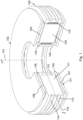
- the first rotor disk 101 comprises magnetic material 107, also referred to as magnets 107 or rotor magnets 107, and typically being permanent magnets.
- the second rotor disk 102 comprises magnetic material 108, also referred to as magnets 108 or rotor magnets 108, and typically being permanent magnets.
- the magnets 107, 108 generate a magnetic flux in axial direction 115.
- the stator housing or clamshell comprises a first cover 103 and a second cover 104.
- the cover plates 103, 104 are perpendicular to the axial direction 115 and form the bottom respectively upper limitation of the stator housing.
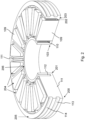
- Fig. 2 shows the stator 100, of which the second cover 104 has been removed.
- the stator 100 comprises a plurality of stator elements 204 being arranged rotationally symmetrical with respect to the central axis 115. Every stator element 204 comprises a coil or winding 110, wound around a ferromagnetic core 109, the cores 109 extending in axial direction 115.
- the first cover plate 103 has an internal side 202 and an external side 203.
- the internal side 202 is directed towards the interior of the stator housing and thus faces the coils 110.
- the external side 203 is directed towards the exterior of the stator housing and thus faces the first air gap 105.
- the first cover 103 is disk-shaped, having a circular outer circumference 200 and a circular inner circumference 201.
- the first cover plate 103 and second cover plate 104 are connected via circumferential walls 205, 205, positioned at the outer respectively inner circumference.
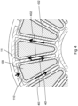
- Fig. 3 and Fig. 4 give a top view of the opened stator 100 of Fig. 2 .
- the stator disk 100 has an outer circumference 300 and an inner circumference 301.
- the inner structure of the stator housing comprises guiding walls 111, wherein a guiding wall 111 is positioned between each pair of adjacent stator elements 204, and extends in radial direction 116.
- the radial walls 111 are connected at one outer end to the outer circumferential wall 205. In axial direction, the radial walls extend between the first cover 103 and second cover 104, thereby connecting both cover plates.
- the outer circumferential wall 205 comprises outer channels 113 and 114, while the space between the guiding wall outer ends and the inner circumferential wall 206 defines an inner channel 112.
- the channels 113, 114 and 112 make part of a cooling circuit for stator cooling, intended for cooling the stator elements 204.
- Such a stator cooling solution is known in the prior art, and is e.g. described in EP3764526A1 .
- the outer and inner channels 113, 114, 112 are arranged to let a stator cooling fluid flow tangentially about the central axis.
- the guiding walls 111 are arranged to let the stator cooling fluid flow in radial direction.
- radial fluid passages are available between every coil 110 and an adjacent radial wall 111.
- cooling fluid is supplied to the cold channel 113 via a supply port, the latter not being shown on the figures.
- Fig. 4 schematically illustrates the stator fluid circulation, indicated by arrows.
- the cooling fluid circulates in tangential direction.
- the cooling fluid flows in radial direction, towards the inner circumference, see arrows 401.
- the fluid is guided by the radial walls 111, thereby being forced to flow against the coils 110 and evacuating heat from the coils 110.
- the fluid is then collected in the inner channel 112.
- the radial flow occurs in the opposite direction, from inner to outer circumference, see arrows 402.
- the heated fluid is collected in the hot channel 114, the latter being connected to a port for draining the stator cooling fluid.
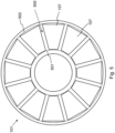
- Fig. 5 gives a top view of the first rotor disk 101. It comprises magnets 107 attached to a disk-shaped plate. The magnets 107 are arranged rotationally symmetrical about the central axis. As is visible on the figure, the magnets 107 together define an annular or ring-shaped zone 500 on the rotor disk. Any of the magnets 107 is positioned within the annular zone 500. The zone 500 is delimited by an inner limit 501 and an outer limit 502. When mounted in the axial flux machine, the top surfaces of the magnets 107 face the first air gap 105, the top surfaces thus being in contact with the air gap 105.
- the second rotor disk 102 has a design similar to the first rotor disk 101.
- Fig. 7 again shows the presence of a guiding wall 111 between every pair of adjacent coils 110.
- the cooling fluid for stator cooling flows in radial direction, via radial fluid passages 700 defined by the coils 110 and guiding walls 111.
- the cooling channel 900 comprises a radial portion 901 and an end portion 902. Both the radial portion 901 and the end portion are provided as channels through stator housing material.
- the radial portion 901 is a channel running through the first cover 103, from the outer circumference 200, 300 towards the inner circumference 201, 301.
- the radial portion 901 may run through a guiding wall 111 instead of the first cover 103.
- the radial portion 901 runs in radial direction.
- the end portion 902 is a channel running through the first cover 103, connecting the radial portion 901 to the spraying element 800.
- the cooling fluid is first transferred via the radial portion 901, thereby flowing in radial direction, from the outer circumference 300 towards the inner circumference 301.
- Such a transport from the outer towards inner circumference is required because the cold channel 113 is located at the outer circumference 300 while the spraying element 800 is located close to the inner circumference 301.
- the cooling fluid flows via the end portion 902 to the exit hole 800, from where it is ejected.
- the radial portion 901 is used in common for cooling of the first and second rotor disk.
- the cooling fluid first flows from the outer towards the inner circumference, via the radial portion 901.
- part of the fluid enters the end portion 902, towards the first spraying element 800, and another part enters the intermediate portion 903, towards the second spraying element 1000.
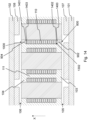
- Fig. 14 illustrates the third embodiment.
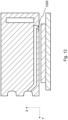
- the third embodiment only differs form the second embodiment in that a plate 1402 separates the bypass channel 1400 from the coil 110.
- the plate 1402 is perpendicular to the axial direction, and substantially parallel to the upper side 1302 of the coil 110. Similar to the second embodiment, a recess or groove 1400 is applied at the internal side 202 of the first cover plate 103.
- the plate 1402 is positioned between the internal side 202 of the first cover 103 and the upper side 1302 of the coil 110.
- the bypass channel 1400 or fluid passage 1400 is thus defined by the plate 1402 and the internal side 202 of the first cover 103.
Landscapes
- Engineering & Computer Science (AREA)
- Power Engineering (AREA)
- Motor Or Generator Cooling System (AREA)
Claims (10)
- Machine à flux axial, comprenant un stator (100) et un rotor comportant un axe central dans une direction axiale (115) correspondant à l'axe de rotation de la machine à flux axial, et le rotor comprenant un premier disque de rotor (101) qui est axialement séparé du stator (100) par un entrefer (105),- ledit stator (100) comprenant une pluralité d'éléments de stator (204) entourés par un boîtier de stator, l'un quelconque des éléments de stator (204) comprenant une bobine (110) enroulée autour d'un noyau (109) ;- ledit premier disque de rotor (101) comprenant des aimants (107) dont les surfaces magnétiques sont situées dans une zone annulaire (500) sur le côté du disque rotor tourné vers l'entrefer (105), et ledit stator (100) comprenant :- un ou plusieurs éléments de pulvérisation (800), chacun des éléments de pulvérisation (800) comprenant au moins un trou de sortie, l'un quelconque des éléments de pulvérisation (800) étant adapté pour éjecter du fluide de refroidissement vers la zone magnétique annulaire (500), de sorte que durant le fonctionnement avec le rotor en rotation, les aimants (107) sont refroidis par un fluide de refroidissement pulvérisé directement sur les surfaces d'aimants respectives, et- un ou plusieurs canaux de refroidissement (900) adaptés pour guider un fluide de refroidissement sous pression vers le ou les éléments de pulvérisation respectifs (800), l'un quelconque du ou des canaux de refroidissement (900) comprenant une partie radiale (901) adaptée pour guider le fluide de refroidissement à partir de l'extérieur (300) vers la circonférence intérieure (301) du stator, et une partie d'extrémité (902) se terminant par l'élément de pulvérisation (800), la partie d'extrémité (902) étant en communication fluidique avec la partie radiale (901),CARACTÉRISÉE EN CE QUE :- le boîtier de stator comprend un premier couvercle (103), le premier couvercle (103) comportant un côté interne (202) tourné vers la face supérieure (1302) des bobines (110) et un côté externe (203) tourné vers l'entrefer (105), ledit ou lesdits éléments de pulvérisation (800) étant prévus sur le premier couvercle (103),- la partie d'extrémité (902) étant prévue sous forme de canal traversant le matériau du premier couvercle (103), et ladite partie radiale (901) étant prévue sous forme de canal traversant le matériau du premier couvercle (103) ou traversant le matériau d'une paroi (111), la paroi (111) étant positionnée entre des éléments de stator adjacents (204).
- Machine à flux axial selon l'une quelconque des revendications précédentes, ledit ou lesdits éléments de pulvérisation (800) étant prévus sous la forme d'un ou plusieurs trous respectifs dans le premier couvercle (103), étant ainsi adaptés pour éjecter le fluide de refroidissement sous la forme d'un jet pointant vers la zone d'aimants (500).
- Machine à flux axial selon l'une quelconque des revendications précédentes, ledit ou lesdits canaux de refroidissement (900) bifurquant d'un circuit de refroidissement pour refroidir les éléments de stator (204).
- Machine à flux axial selon l'une quelconque des revendications précédentes, ledit fluide de refroidissement étant un liquide de refroidissement, par exemple de l'huile.
- Machine à flux axial selon l'une quelconque des revendications précédentes, ledit premier couvercle (103) comportant une circonférence externe (200) et une circonférence intérieure (201), et l'un quelconque du ou des éléments de pulvérisation (800) étant situé au niveau d'une position radiale plus proche de la circonférence intérieure (201) que de la circonférence extérieure (200).
- Machine à flux axial selon l'une quelconque des revendications précédentes, l'un quelconque du ou des canaux de refroidissement (900) étant en communication fluidique avec une entrée de fluide située au niveau de la circonférence extérieure (300) du stator (100), de sorte que, durant le fonctionnement, le fluide de refroidissement soit guidé à partir de l'extérieur (300) vers la circonférence intérieure (301) du stator, avant d'être éjecté par l'intermédiaire du ou des éléments de pulvérisation (800).
- Machine à flux axial selon l'une quelconque des revendications précédentes, lesdits noyaux (109) des éléments de stator (204) s'étendant à travers le premier couvercle (103), de sorte que des surfaces des noyaux respectifs (109) soient en contact avec l'entrefer (105), et durant le fonctionnement de la machine, au moins une partie du fluide de refroidissement éjecté par le ou les éléments de pulvérisation (800) aspergeant les surfaces du noyau, refroidissant ainsi les noyaux (109).
- Machine à flux axial selon l'une quelconque des revendications précédentes :- ledit rotor comprenant un second disque de rotor (102) séparé axialement du stator (100) par un second entrefer (106) ;- ledit boîtier de stator comprenant un second couvercle (104) faisant face au second entrefer (106) ;- ledit second disque de rotor (102) comprenant des aimants (108) dont les surfaces d'aimants sont situées dans une zone annulaire (500) sur le côté du disque tourné vers le second entrefer (106),et ledit stator (100) comprenant :- un second ensemble d'un ou plusieurs éléments de pulvérisation (1000) prévus sur le second couvercle (104), chacun des éléments de pulvérisation (1000) comprenant au moins un trou de sortie, et- un second ensemble d'un ou plusieurs canaux de refroidissement adaptés pour guider un fluide de refroidissement sous pression vers le ou les éléments de pulvérisation respectifs (1000) du second ensemble,l'un quelconque des éléments de pulvérisation (1000) étant adapté pour éjecter du fluide de refroidissement vers la zone d'aimants annulaire du second disque de rotor (102), de sorte que durant le fonctionnement avec un rotor en rotation, lesdits aimants (108) du second disque de rotor (102) soient refroidis par un fluide de refroidissement pulvérisé directement sur les surfaces d'aimants respectives.
- Machine à flux axial selon la revendication 8, l'un quelconque du ou des canaux de refroidissement du second ensemble comprenant une partie finale (904) prévue sous forme de canal à travers le matériau du second couvercle (104) et se terminant dans l'élément de pulvérisation (1000) du second ensemble, ladite partie finale (904) étant en communication fluidique avec la partie radiale (901) adaptée pour guider le fluide de refroidissement à partir de l'extérieur (300) vers la circonférence intérieure (301) du stator.
- Machine à flux axial selon la revendication 9 :- ledit stator (100) comprenant au moins une paroi (111), la paroi (111) étant positionnée entre deux éléments de stator (204) adjacents et s'étendant axialement entre le premier (103) et le second couvercle (104) ;- ladite partie radiale (901) étant prévue sous forme de canal traversant le matériau du premier couvercle (103), ou traversant le matériau de la paroi (111), et- l'un quelconque du ou des canaux de refroidissement du second ensemble comprenant une partie intermédiaire (903) prévue sous forme de canal traversant le matériau de la paroi (111), la partie intermédiaire (903) étant en communication fluidique avec à la fois la partie radiale (901) et la partie finale (904).
Priority Applications (6)
| Application Number | Priority Date | Filing Date | Title |
|---|---|---|---|
| EP24178247.3A EP4418506A3 (fr) | 2022-07-18 | 2022-07-18 | Machine à flux axial avec refroidissement direct par aimant |
| EP22185393.0A EP4311078B1 (fr) | 2022-07-18 | 2022-07-18 | Machine à flux axial avec refroidissement direct de l'aimant |
| CN202380054719.0A CN119585978A (zh) | 2022-07-18 | 2023-05-25 | 具有直接磁体冷却的轴向磁通机 |
| US18/997,176 US20260031666A1 (en) | 2022-07-18 | 2023-05-25 | Axial flux machine with direct magnet cooling |
| PCT/EP2023/064051 WO2024017526A1 (fr) | 2022-07-18 | 2023-05-25 | Machine à flux axial à refroidissement direct des aimants |
| TW112124322A TW202423007A (zh) | 2022-07-18 | 2023-06-29 | 具有直接磁性冷卻的軸向磁通電機 |
Applications Claiming Priority (1)
| Application Number | Priority Date | Filing Date | Title |
|---|---|---|---|
| EP22185393.0A EP4311078B1 (fr) | 2022-07-18 | 2022-07-18 | Machine à flux axial avec refroidissement direct de l'aimant |
Related Child Applications (2)
| Application Number | Title | Priority Date | Filing Date |
|---|---|---|---|
| EP24178247.3A Division EP4418506A3 (fr) | 2022-07-18 | 2022-07-18 | Machine à flux axial avec refroidissement direct par aimant |
| EP24178247.3A Division-Into EP4418506A3 (fr) | 2022-07-18 | 2022-07-18 | Machine à flux axial avec refroidissement direct par aimant |
Publications (3)
| Publication Number | Publication Date |
|---|---|
| EP4311078A1 EP4311078A1 (fr) | 2024-01-24 |
| EP4311078C0 EP4311078C0 (fr) | 2024-07-10 |
| EP4311078B1 true EP4311078B1 (fr) | 2024-07-10 |
Family
ID=82611148
Family Applications (2)
| Application Number | Title | Priority Date | Filing Date |
|---|---|---|---|
| EP22185393.0A Active EP4311078B1 (fr) | 2022-07-18 | 2022-07-18 | Machine à flux axial avec refroidissement direct de l'aimant |
| EP24178247.3A Pending EP4418506A3 (fr) | 2022-07-18 | 2022-07-18 | Machine à flux axial avec refroidissement direct par aimant |
Family Applications After (1)
| Application Number | Title | Priority Date | Filing Date |
|---|---|---|---|
| EP24178247.3A Pending EP4418506A3 (fr) | 2022-07-18 | 2022-07-18 | Machine à flux axial avec refroidissement direct par aimant |
Country Status (5)
| Country | Link |
|---|---|
| US (1) | US20260031666A1 (fr) |
| EP (2) | EP4311078B1 (fr) |
| CN (1) | CN119585978A (fr) |
| TW (1) | TW202423007A (fr) |
| WO (1) | WO2024017526A1 (fr) |
Cited By (4)
| Publication number | Priority date | Publication date | Assignee | Title |
|---|---|---|---|---|
| US12483103B2 (en) | 2020-04-24 | 2025-11-25 | Jacobi Motors, Llc | Flux-mnemonic permanent magnet synchronous machine and magnetizing a flux-mnemonic permanent magnet synchronous machine |
| US12558980B2 (en) | 2023-11-09 | 2026-02-24 | Jacobi Motors, Llc | Integrated variable flux memory motor charger |
| US12614998B2 (en) | 2024-03-04 | 2026-04-28 | Jacobi Motors, Llc | System for multi-variable flux memory motor configuration |
| US12620920B2 (en) | 2023-10-26 | 2026-05-05 | Jacobi Motors, Llc | System and method for shifting operation modes of variable flux memory motors |
Families Citing this family (5)
| Publication number | Priority date | Publication date | Assignee | Title |
|---|---|---|---|---|
| DE102024202386A1 (de) | 2024-03-14 | 2025-09-18 | Schaeffler Technologies AG & Co. KG | Stator für eine Axialflussmaschine mit axial ausgerichteter Kühlmittelauslass, Axialflussmaschine und Traktionsantrieb |
| DE102024002964A1 (de) * | 2024-09-13 | 2026-03-19 | Mercedes-Benz Group AG | Axialflussmaschine für ein Kraftfahrzeug sowie Verfahren zum Betreiben einer solchen Axialflussmaschine |
| DE102024002965A1 (de) * | 2024-09-13 | 2026-03-19 | Mercedes-Benz Group AG | Axialflussmaschine für ein Kraftfahrzeug sowie Verfahren zum Betreiben einer solchen Axialflussmaschine |
| CN118920767A (zh) * | 2024-09-26 | 2024-11-08 | 新疆龟兹矿业有限公司 | 一种电机主动风冷系统与主动冷却方法 |
| CN120185278B (zh) * | 2025-03-27 | 2025-09-26 | 临沂大学 | 航空驱动电机、飞行器推进装置及飞行器 |
Family Cites Families (5)
| Publication number | Priority date | Publication date | Assignee | Title |
|---|---|---|---|---|
| GB2519060B (en) | 2013-08-08 | 2016-08-03 | Yasa Motors Ltd | Cooling of axial flux motors - centrifugal |
| FR3028689A3 (fr) * | 2014-11-13 | 2016-05-20 | Renault Sa | Moteur electrique comprenant un circuit de refroidissement du rotor. |
| GB2538526B (en) | 2015-05-19 | 2021-05-26 | Yasa Ltd | Axial flux machine |
| EP3764526A1 (fr) | 2019-07-10 | 2021-01-13 | Magnax Bv | Mécanisme de refroidissement d'un stator pour une machine à flux axial |
| US11569713B2 (en) * | 2020-03-13 | 2023-01-31 | GM Global Technology Operations LLC | Axial flux motor including system for circulating coolant through air gap between stator and rotor |
-
2022
- 2022-07-18 EP EP22185393.0A patent/EP4311078B1/fr active Active
- 2022-07-18 EP EP24178247.3A patent/EP4418506A3/fr active Pending
-
2023
- 2023-05-25 WO PCT/EP2023/064051 patent/WO2024017526A1/fr not_active Ceased
- 2023-05-25 CN CN202380054719.0A patent/CN119585978A/zh active Pending
- 2023-05-25 US US18/997,176 patent/US20260031666A1/en active Pending
- 2023-06-29 TW TW112124322A patent/TW202423007A/zh unknown
Cited By (4)
| Publication number | Priority date | Publication date | Assignee | Title |
|---|---|---|---|---|
| US12483103B2 (en) | 2020-04-24 | 2025-11-25 | Jacobi Motors, Llc | Flux-mnemonic permanent magnet synchronous machine and magnetizing a flux-mnemonic permanent magnet synchronous machine |
| US12620920B2 (en) | 2023-10-26 | 2026-05-05 | Jacobi Motors, Llc | System and method for shifting operation modes of variable flux memory motors |
| US12558980B2 (en) | 2023-11-09 | 2026-02-24 | Jacobi Motors, Llc | Integrated variable flux memory motor charger |
| US12614998B2 (en) | 2024-03-04 | 2026-04-28 | Jacobi Motors, Llc | System for multi-variable flux memory motor configuration |
Also Published As
| Publication number | Publication date |
|---|---|
| EP4418506A2 (fr) | 2024-08-21 |
| CN119585978A (zh) | 2025-03-07 |
| US20260031666A1 (en) | 2026-01-29 |
| WO2024017526A1 (fr) | 2024-01-25 |
| EP4311078C0 (fr) | 2024-07-10 |
| EP4311078A1 (fr) | 2024-01-24 |
| EP4418506A3 (fr) | 2024-11-06 |
| TW202423007A (zh) | 2024-06-01 |
Similar Documents
| Publication | Publication Date | Title |
|---|---|---|
| EP4311078B1 (fr) | Machine à flux axial avec refroidissement direct de l'aimant | |
| US10707726B2 (en) | Cooling structure for dynamo-electric machine | |
| CN109997296B (zh) | 用于冷却电机的方法以及使用这种方法的电机 | |
| JP4424385B2 (ja) | 回転電機 | |
| US6304011B1 (en) | Rotary electrical machines | |
| EP2573906B1 (fr) | Machine électrique à pertes de tourbillonnement réduites | |
| US8487489B2 (en) | Apparatus for cooling an electric machine | |
| EP0764358B1 (fr) | Moteur electrique a induction et procede de refroidissement | |
| JP4560067B2 (ja) | 回転電機 | |
| US11277056B2 (en) | Fluid-cooled rotor for an electric machine | |
| EP0153318B1 (fr) | Generateur a haute vitesse avec event pour entrefer | |
| WO2019187021A1 (fr) | Structure de refroidissement destinée à un dispositif électrique rotatif | |
| CN111181281A (zh) | 用于冷却旋转电机中的端部绕组的设备和方法 | |
| WO2020176572A1 (fr) | Machine électrique à passages de refroidissement internes | |
| EP4407848B1 (fr) | Machine électrique tournante | |
| EP4412057B1 (fr) | Machine électrique rotative | |
| JP2010172129A (ja) | 回転電機の冷却方法及び回転電機の冷却装置 | |
| JP2002354753A (ja) | 回転電機 | |
| CN224021521U (zh) | 转子组件、电机、动力总成及车辆 | |
| US12614940B2 (en) | Cooling of high-power permanent magnet machine rotor | |
| CA1213301A (fr) | Event sur circuit d'huile du rotor d'une generatrice tournant a haute vitesse | |
| US20240322648A1 (en) | Electric machine | |
| CN119182247A (zh) | 用于电励磁同步马达(eesm)的转子组件 | |
| CN114649889A (zh) | 转子和具有这种转子的电动机器 | |
| JP2025168824A (ja) | 巻線界磁型同期モータ(eesm)用のロータアセンブリ |
Legal Events
| Date | Code | Title | Description |
|---|---|---|---|
| PUAI | Public reference made under article 153(3) epc to a published international application that has entered the european phase |
Free format text: ORIGINAL CODE: 0009012 |
|
| STAA | Information on the status of an ep patent application or granted ep patent |
Free format text: STATUS: REQUEST FOR EXAMINATION WAS MADE |
|
| 17P | Request for examination filed |
Effective date: 20230428 |
|
| AK | Designated contracting states |
Kind code of ref document: A1 Designated state(s): AL AT BE BG CH CY CZ DE DK EE ES FI FR GB GR HR HU IE IS IT LI LT LU LV MC MK MT NL NO PL PT RO RS SE SI SK SM TR |
|
| GRAP | Despatch of communication of intention to grant a patent |
Free format text: ORIGINAL CODE: EPIDOSNIGR1 |
|
| STAA | Information on the status of an ep patent application or granted ep patent |
Free format text: STATUS: GRANT OF PATENT IS INTENDED |
|
| INTG | Intention to grant announced |
Effective date: 20240215 |
|
| GRAS | Grant fee paid |
Free format text: ORIGINAL CODE: EPIDOSNIGR3 |
|
| GRAA | (expected) grant |
Free format text: ORIGINAL CODE: 0009210 |
|
| STAA | Information on the status of an ep patent application or granted ep patent |
Free format text: STATUS: THE PATENT HAS BEEN GRANTED |
|
| AK | Designated contracting states |
Kind code of ref document: B1 Designated state(s): AL AT BE BG CH CY CZ DE DK EE ES FI FR GB GR HR HU IE IS IT LI LT LU LV MC MK MT NL NO PL PT RO RS SE SI SK SM TR |
|
| REG | Reference to a national code |
Ref country code: CH Ref legal event code: EP |
|
| REG | Reference to a national code |
Ref country code: DE Ref legal event code: R096 Ref document number: 602022004424 Country of ref document: DE |
|
| U01 | Request for unitary effect filed |
Effective date: 20240808 |
|
| U07 | Unitary effect registered |
Designated state(s): AT BE BG DE DK EE FI FR IT LT LU LV MT NL PT SE SI Effective date: 20240821 |
|
| U20 | Renewal fee for the european patent with unitary effect paid |
Year of fee payment: 3 Effective date: 20241121 |
|
| PG25 | Lapsed in a contracting state [announced via postgrant information from national office to epo] |
Ref country code: NO Free format text: LAPSE BECAUSE OF FAILURE TO SUBMIT A TRANSLATION OF THE DESCRIPTION OR TO PAY THE FEE WITHIN THE PRESCRIBED TIME-LIMIT Effective date: 20241010 |
|
| PG25 | Lapsed in a contracting state [announced via postgrant information from national office to epo] |
Ref country code: GR Free format text: LAPSE BECAUSE OF FAILURE TO SUBMIT A TRANSLATION OF THE DESCRIPTION OR TO PAY THE FEE WITHIN THE PRESCRIBED TIME-LIMIT Effective date: 20241011 Ref country code: PL Free format text: LAPSE BECAUSE OF FAILURE TO SUBMIT A TRANSLATION OF THE DESCRIPTION OR TO PAY THE FEE WITHIN THE PRESCRIBED TIME-LIMIT Effective date: 20240710 |
|
| PG25 | Lapsed in a contracting state [announced via postgrant information from national office to epo] |
Ref country code: IS Free format text: LAPSE BECAUSE OF FAILURE TO SUBMIT A TRANSLATION OF THE DESCRIPTION OR TO PAY THE FEE WITHIN THE PRESCRIBED TIME-LIMIT Effective date: 20241110 |
|
| PG25 | Lapsed in a contracting state [announced via postgrant information from national office to epo] |
Ref country code: HR Free format text: LAPSE BECAUSE OF FAILURE TO SUBMIT A TRANSLATION OF THE DESCRIPTION OR TO PAY THE FEE WITHIN THE PRESCRIBED TIME-LIMIT Effective date: 20240710 |
|
| PG25 | Lapsed in a contracting state [announced via postgrant information from national office to epo] |
Ref country code: ES Free format text: LAPSE BECAUSE OF FAILURE TO SUBMIT A TRANSLATION OF THE DESCRIPTION OR TO PAY THE FEE WITHIN THE PRESCRIBED TIME-LIMIT Effective date: 20240710 Ref country code: RS Free format text: LAPSE BECAUSE OF FAILURE TO SUBMIT A TRANSLATION OF THE DESCRIPTION OR TO PAY THE FEE WITHIN THE PRESCRIBED TIME-LIMIT Effective date: 20241010 |
|
| PG25 | Lapsed in a contracting state [announced via postgrant information from national office to epo] |
Ref country code: RS Free format text: LAPSE BECAUSE OF FAILURE TO SUBMIT A TRANSLATION OF THE DESCRIPTION OR TO PAY THE FEE WITHIN THE PRESCRIBED TIME-LIMIT Effective date: 20241010 Ref country code: PL Free format text: LAPSE BECAUSE OF FAILURE TO SUBMIT A TRANSLATION OF THE DESCRIPTION OR TO PAY THE FEE WITHIN THE PRESCRIBED TIME-LIMIT Effective date: 20240710 Ref country code: NO Free format text: LAPSE BECAUSE OF FAILURE TO SUBMIT A TRANSLATION OF THE DESCRIPTION OR TO PAY THE FEE WITHIN THE PRESCRIBED TIME-LIMIT Effective date: 20241010 Ref country code: IS Free format text: LAPSE BECAUSE OF FAILURE TO SUBMIT A TRANSLATION OF THE DESCRIPTION OR TO PAY THE FEE WITHIN THE PRESCRIBED TIME-LIMIT Effective date: 20241110 Ref country code: HR Free format text: LAPSE BECAUSE OF FAILURE TO SUBMIT A TRANSLATION OF THE DESCRIPTION OR TO PAY THE FEE WITHIN THE PRESCRIBED TIME-LIMIT Effective date: 20240710 Ref country code: GR Free format text: LAPSE BECAUSE OF FAILURE TO SUBMIT A TRANSLATION OF THE DESCRIPTION OR TO PAY THE FEE WITHIN THE PRESCRIBED TIME-LIMIT Effective date: 20241011 Ref country code: ES Free format text: LAPSE BECAUSE OF FAILURE TO SUBMIT A TRANSLATION OF THE DESCRIPTION OR TO PAY THE FEE WITHIN THE PRESCRIBED TIME-LIMIT Effective date: 20240710 |
|
| PG25 | Lapsed in a contracting state [announced via postgrant information from national office to epo] |
Ref country code: SM Free format text: LAPSE BECAUSE OF FAILURE TO SUBMIT A TRANSLATION OF THE DESCRIPTION OR TO PAY THE FEE WITHIN THE PRESCRIBED TIME-LIMIT Effective date: 20240710 |
|
| PG25 | Lapsed in a contracting state [announced via postgrant information from national office to epo] |
Ref country code: MC Free format text: LAPSE BECAUSE OF FAILURE TO SUBMIT A TRANSLATION OF THE DESCRIPTION OR TO PAY THE FEE WITHIN THE PRESCRIBED TIME-LIMIT Effective date: 20240710 |
|
| PG25 | Lapsed in a contracting state [announced via postgrant information from national office to epo] |
Ref country code: CZ Free format text: LAPSE BECAUSE OF FAILURE TO SUBMIT A TRANSLATION OF THE DESCRIPTION OR TO PAY THE FEE WITHIN THE PRESCRIBED TIME-LIMIT Effective date: 20240710 |
|
| PG25 | Lapsed in a contracting state [announced via postgrant information from national office to epo] |
Ref country code: SK Free format text: LAPSE BECAUSE OF FAILURE TO SUBMIT A TRANSLATION OF THE DESCRIPTION OR TO PAY THE FEE WITHIN THE PRESCRIBED TIME-LIMIT Effective date: 20240710 |
|
| PLBE | No opposition filed within time limit |
Free format text: ORIGINAL CODE: 0009261 |
|
| STAA | Information on the status of an ep patent application or granted ep patent |
Free format text: STATUS: NO OPPOSITION FILED WITHIN TIME LIMIT |
|
| U1N | Appointed representative for the unitary patent procedure changed after the registration of the unitary effect |
Representative=s name: DE CLERCQ & PARTNERS; BE |
|
| 26N | No opposition filed |
Effective date: 20250411 |
|
| PG25 | Lapsed in a contracting state [announced via postgrant information from national office to epo] |
Ref country code: IE Free format text: LAPSE BECAUSE OF NON-PAYMENT OF DUE FEES Effective date: 20240718 |
|
| U20 | Renewal fee for the european patent with unitary effect paid |
Year of fee payment: 4 Effective date: 20250715 |
|
| PG25 | Lapsed in a contracting state [announced via postgrant information from national office to epo] |
Ref country code: RO Free format text: LAPSE BECAUSE OF FAILURE TO SUBMIT A TRANSLATION OF THE DESCRIPTION OR TO PAY THE FEE WITHIN THE PRESCRIBED TIME-LIMIT Effective date: 20240710 |
|
| PG25 | Lapsed in a contracting state [announced via postgrant information from national office to epo] |
Ref country code: CY Free format text: LAPSE BECAUSE OF FAILURE TO SUBMIT A TRANSLATION OF THE DESCRIPTION OR TO PAY THE FEE WITHIN THE PRESCRIBED TIME-LIMIT; INVALID AB INITIO Effective date: 20220718 |
|
| REG | Reference to a national code |
Ref country code: CH Ref legal event code: H13 Free format text: ST27 STATUS EVENT CODE: U-0-0-H10-H13 (AS PROVIDED BY THE NATIONAL OFFICE) Effective date: 20260224 |
|
| PG25 | Lapsed in a contracting state [announced via postgrant information from national office to epo] |
Ref country code: HU Free format text: LAPSE BECAUSE OF FAILURE TO SUBMIT A TRANSLATION OF THE DESCRIPTION OR TO PAY THE FEE WITHIN THE PRESCRIBED TIME-LIMIT; INVALID AB INITIO Effective date: 20220718 |
|
| PG25 | Lapsed in a contracting state [announced via postgrant information from national office to epo] |
Ref country code: CH Free format text: LAPSE BECAUSE OF NON-PAYMENT OF DUE FEES Effective date: 20250731 |