EP4311087B1 - Procédé d'empilage pour empiler des fils enroulés sur des arbres, magasin pour utilisation dans ce procédé et utilisations de celui-ci - Google Patents
Procédé d'empilage pour empiler des fils enroulés sur des arbres, magasin pour utilisation dans ce procédé et utilisations de celui-ci Download PDFInfo
- Publication number
- EP4311087B1 EP4311087B1 EP22202369.9A EP22202369A EP4311087B1 EP 4311087 B1 EP4311087 B1 EP 4311087B1 EP 22202369 A EP22202369 A EP 22202369A EP 4311087 B1 EP4311087 B1 EP 4311087B1
- Authority
- EP
- European Patent Office
- Prior art keywords
- wave winding
- magazine
- receiving space
- workpiece carrier
- wires
- Prior art date
- Legal status (The legal status is an assumption and is not a legal conclusion. Google has not performed a legal analysis and makes no representation as to the accuracy of the status listed.)
- Active
Links
Images








Classifications
-
- H—ELECTRICITY
- H02—GENERATION; CONVERSION OR DISTRIBUTION OF ELECTRIC POWER
- H02K—DYNAMO-ELECTRIC MACHINES
- H02K15/00—Processes or apparatus specially adapted for manufacturing, assembling, maintaining or repairing of dynamo-electric machines
- H02K15/04—Processes or apparatus specially adapted for manufacturing, assembling, maintaining or repairing of dynamo-electric machines of windings prior to their mounting into the machines
- H02K15/043—Processes or apparatus specially adapted for manufacturing, assembling, maintaining or repairing of dynamo-electric machines of windings prior to their mounting into the machines winding flat conductive wires or sheets
-
- H—ELECTRICITY
- H02—GENERATION; CONVERSION OR DISTRIBUTION OF ELECTRIC POWER
- H02K—DYNAMO-ELECTRIC MACHINES
- H02K15/00—Processes or apparatus specially adapted for manufacturing, assembling, maintaining or repairing of dynamo-electric machines
- H02K15/04—Processes or apparatus specially adapted for manufacturing, assembling, maintaining or repairing of dynamo-electric machines of windings prior to their mounting into the machines
- H02K15/043—Processes or apparatus specially adapted for manufacturing, assembling, maintaining or repairing of dynamo-electric machines of windings prior to their mounting into the machines winding flat conductive wires or sheets
- H02K15/0432—Distributed windings
- H02K15/0433—Distributed windings of the wave winding type
-
- B—PERFORMING OPERATIONS; TRANSPORTING
- B21—MECHANICAL METAL-WORKING WITHOUT ESSENTIALLY REMOVING MATERIAL; PUNCHING METAL
- B21F—WORKING OR PROCESSING OF METAL WIRE
- B21F3/00—Coiling wire into particular forms
- B21F3/08—Coiling wire into particular forms to flat spiral
Definitions
- the invention relates to a stacking method for stacking wave winding wires to form a winding mat for a coil winding of a stator.
- the invention further relates to a manufacturing method for producing a winding mat for a coil winding of a stator, wherein the manufacturing method includes stacking wave winding wires using the stacking method.
- the invention further relates to a magazine for use in the stacking method, a stacking device for stacking wave winding wires with at least one such magazine, a controller and a computer program for such a stacking device, and a manufacturing device for producing a wave winding mat that is provided with such a stacking device.
- a winding mat is formed from several individual wires in which straight wire sections that are inserted into stator slots are connected to one another by roof-shaped bent sections, the so-called winding heads.
- the individual wires are formed from a core made of conductive metal, usually copper, and an external insulation layer. In order to achieve a high degree of filling, the individual wires often have an essentially rectangular cross-section.
- a manufacturing process known from [8] for such coil windings formed from a winding mat is the so-called sword winding, in which the individual wires are wound onto a template (sword), creating winding mats with spirally bent wires. This manufacturing process causes the winding heads to be twisted. The wires are subject to severe deformation. Severe deformation can impair the insulation and increase the space required for the winding heads.
- Reference [11] describes another bending method for bending wire sections for a wave winding mat for forming a coil winding of a component of an electrical machine, wherein a wire group is provided and the wires of the wire group are bent into a meander shape.
- winding mats can also be produced from several flatly bent wave winding wires, as described and shown in the literature references [1] to [7] and [10].
- wave winding wires are individual wires bent in a meandering shape.
- the wave winding wires can be intertwined, woven, plugged or stacked. Automated processes for weaving or interlacing the bent wires to form a wave winding mat are known for this purpose.
- the reference [3] describes a process in which the bent wires are positioned relative to each other and then gradually woven together by rotating the individual wires.
- the bent wires are interwoven with each other.
- the reference [2] discloses a method in which the conductors are bent in sections so that a second conductor can be placed on top and a conductor pair is formed by bending the first conductor back.
- a method for inserting the winding wires is described in the reference [4], in which two bent wave winding wires are positioned relative to each other in such a way that they can be pushed into each other by arranging the wave winding wires in sections above or below the other wire.
- a device in which a single wave winding wire is transported with an endless conveyor belt and is then inserted into another holder by raising and lowering guide rails.
- the wave winding which is usually prefabricated as a linear coil, can have different head designs.
- the wire mat can now be constructed from, for example, six wires with the same head, or with an additional exchange between two parallel conductors in the head, as is the case, for example, in [1], Fig.2 and 4 is shown.
- each wave winding mat can have its own stacking sequence of different individual wires, as described and shown in particular in the reference [7].
- the object of the invention is to provide methods and devices with which different wave winding mats can be produced from wave winding wires in an automated and reliable manner.
- the invention provides a stacking method according to claim 1.
- a computer program for this purpose and a manufacturing device for a coil winding are the subject of the dependent claims.
- the depositing includes the step: Separating the lowest wave winding wire of the magazine to be deposited by means of a separating device which moves the wave winding wire to be deposited from the receiving space to a deposit position, wherein the wave winding wire is held and/or guided during the displacement in such a way that its geometry is maintained.
- the depositing includes the step: Feeding of wave winding wires in the receiving space in a vertical direction downwards.
- the depositing includes the step: Guiding the wave winding wires in the receiving space so that the geometry is maintained.
- the depositing includes the step: Applying a vertical force to the wave winding wires arranged in the receiving space from above in order to guide the wave winding wires and/or to position them in the receiving space in a vertical direction and/or to press them against a shelf provided in the lower area.
- the depositing includes the step: Using a slider, which can be moved transversely to the longitudinal direction of the wave winding wires, as a storage device to prevent wave winding wires from accidentally falling out of the receiving space and/or as a separating device.
- the depositing includes the step: Active insertion of the wave winding wire to be deposited into the holding structures by insertion elements moved in vertical direction.
- positioning comprises the step: Positioning the holding structure in the transverse direction, which extends transversely to the longitudinal extent of the wave winding wires received in the receiving space, at a storage position offset in the transverse direction relative to the receiving space.
- positioning comprises the step: Positioning the workpiece carrier in the longitudinal direction, which extends in the direction of the longitudinal extent of the wave winding wires received in the receiving space, at a transfer position offset in the longitudinal direction from a previous transfer position.
- positioning comprises the step: Positioning the workpiece carrier vertically in the transfer position such that the holding structures overlap vertically with guides of the magazine.
- the invention provides a manufacturing method for producing a winding mat for a coil winding of a stator, comprising carrying out the stacking method according to one of the preceding embodiments (also in any combination with one another) to obtain a stack of wave winding wires, wherein winding heads are arranged on both sides of the stack, and embossing the stack on the workpiece carrier in the region of the winding heads.
- the invention provides a magazine for use in the stacking method according to one of the preceding embodiments, comprising a meander-shaped receiving space for a plurality of identical wave winding wires with lateral guides for precisely fitting, tension-free guiding and/or lateral positioning of the wave winding wires, wherein the receiving space extends vertically through the magazine with at least one directional component; a storage guide for depositing a wave winding wire at a storage position which is arranged relative to the receiving space in a transverse direction which extends transversely to the longitudinal extension of the meander-shaped receiving space, and a positioning device for positioning a workpiece carrier with holding structure in the transverse direction and in a longitudinal direction.
- the receiving space is formed by a boundary made up of several exchangeable segmented magazine parts.
- the magazine further comprises a separating device for laterally displacing the lowermost wave winding wire from the receiving space to the storage position with guides for maintaining the geometry of the wave winding wire.
- the magazine further comprises a slider which can be moved back and forth in the transverse direction as a storage device to prevent the wave winding wires from falling out of the Receiving space downwards and/or for separating the lowest wave winding wire by laterally moving it from the receiving space to the storage position.
- a slider which can be moved back and forth in the transverse direction as a storage device to prevent the wave winding wires from falling out of the Receiving space downwards and/or for separating the lowest wave winding wire by laterally moving it from the receiving space to the storage position.
- the stacking device has insertion elements for actively inserting the wave winding wire to be deposited into the holding structure.
- the stacking device comprises a hold-down device for exerting a vertical force on the wave winding wires in the receiving space.
- the stacking device comprises a first magazine, which is designed according to one of the preceding embodiments, for receiving first wave winding wires and a second magazine, which is preferably also designed according to one of the preceding embodiments, with a differently contoured receiving space for receiving second wave winding wires that are different from the first wave winding wires, wherein the movement device is designed to move the workpiece carrier between storage positions of the first and second magazines - preferably, but not necessarily, with different offsets in the longitudinal direction.
- the invention provides a controller for a stacking device according to one of the preceding embodiments, wherein the controller is designed to control the stacking device for carrying out the stacking method according to one of the preceding embodiments.
- the invention provides a computer program containing control instructions which cause a stacking device according to one of the preceding embodiments to carry out the stacking method according to one of the preceding embodiments.
- the invention provides a manufacturing device for producing a winding mat for a coil winding of a stator, comprising a stacking device according to one of the preceding embodiments and a press which is designed to emboss winding heads of a stack of wave winding wires formed on the workpiece carrier on the workpiece carrier.
- Preferred embodiments of the methods, devices and apparatuses according to the invention relate to or enable a shape and position accurate transfer of a wave winding wire without intermediate handling.
- wave winding mats also with conductor exchange as known from [1]
- different bent wave winding wires as known from [2]
- wave winding wires with different cross-sections as known from [7] can be manufactured very gently by stacking them in an automated manner.
- deformations and twistings and other heavy loads on the individual wires are avoided so that the risk of damage is reduced.
- a particular advantage of the embodiments according to the invention is that wires can be stacked to form mats, whereby it is ensured that the already wave-shaped wire reliably retains its shape and position during handling.
- Stacking can be done in different ways, i.e. either individually on top of each other or as pre-grouped individual wires.
- the wave winding wires themselves can also have the same contour or, due to electrical advantages, different contours, which makes handling significantly more difficult.
- the alignment with each other is provided in order to be able to transfer the finished wave winding mat to a corresponding receiver, e.g. a mandrel with narrow grooves, see [9], and then to insert it into a stator or rotor.
- each wave winding mat can have its own stacking order, which, as already mentioned, can be made up of several identical or several different individual wires, or of a group of individual wires, and should be adhered to exactly.
- Each wave winding wire can have a different cross-section, length and width, as well as the bend of the roof (spacing, head shape).
- Preferred embodiments of the invention provide methods, devices and apparatuses which make it possible to assemble the different wave winding wires in an automated and precisely positioned manner to form a stacked mat.
- each individual meander-shaped wire (wave winding wire) is always kept in a defined shape - preferably during the entire process.
- Some embodiments of the invention therefore describe a device in the form of a magazine, in particular a type of Drop magazine in which the wave winding wire is deposited along its contour in such a way that it cannot slip and its geometry cannot change.
- a workpiece holder - hereinafter referred to as the workpiece carrier - is positioned and lifted out beneath the device that acts as a magazine.
- the workpiece carrier is also constructed in such a way that the individual wires are held in their shape.
- a positioning device is provided for the relative positioning of the magazine and workpiece carrier.
- the contours are interlocked by immersing the workpiece carrier in the magazine, in particular the drop magazine, which makes it possible to transfer the wire in a defined manner and without intermediate handling.
- any 2D shape of the wire can be stacked using multi-segmented magazine parts.
- the parts - especially the entire magazine housing - can also be made from one piece.
- Each wave winding wire is always kept in shape by the interaction of the individual magazine parts at several points.
- the lower part of the workpiece carrier described above which can also be multi-segmented or made from one piece, holds the wire in a defined shape using simple bolts.
- This modular design has the advantage that a change in the geometry of the wave winding wire/mat can be quickly and easily converted.
- the wave-shaped individual wires must have a height offset before a coil mat can be stacked.
- a single wave winding wire is formed by an embossing device on the winding heads and then conveyed to a loading station using an endless conveyor belt and guide rails. Only in the loading station is the wire positioned in the correct place in the workpiece carrier by raising and lowering the guide rails.
- several individual mats can be placed on top of one another without any intermediate handling and stacked to form a mat.
- Intermediate bends of the individual wires which are also required for braiding (see e.g. [2]), can be omitted in embodiments of the invention, and the actuators for depositing the individual wires in the receiver can be designed much more simply.
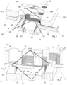
- FIG.1 An embodiment of the magazine 14 is shown in the Fig.1 alone and in the Fig. 2 to 4 and 9a to 11 shown as part of the stacking device 16.
- the stacking method first comprises the step of providing at least one magazine 14 which contains a plurality of identical wave winding wires 10 in a receiving space 18.
- the magazine 14 is designed as a drop magazine, so that the receiving space 18 extends with at least one directional component in the vertical direction through the magazine 14.
- the contour of the receiving space 18 is adapted to the received wave winding wires 10, so that the wave winding wires 10 are positioned on several guides 20 at different points on the boundary of the receiving space 18 and are guided through the receiving space 18 without changing their geometry.
- the stacking method further comprises the step of positioning a workpiece carrier 22, which is provided with a holding structure 24 for a winding mat 12 formed from a plurality of stacked wave winding wires 10, in a first transfer position 23 below the at least one magazine 14 and depositing a wave winding wire 10 from the at least one magazine 14 on a first position 21.1 on the workpiece carrier 22.
- An embodiment of the workpiece carrier 22 is shown as part of the stacking device 16, for example in the Fig. 2 to 4 and 9a-10h, where Fig. 3 and 4 show the step of positioning at the first transfer position 23 and, for example, the Fig. 9f and 10f show an example of the step of depositing.
- Fig. 14a shows an example of the first position 21.1, in which a first wave winding wire 10a is placed on the workpiece carrier 22.
- the stacking method further comprises the step of positioning the workpiece carrier 22 in a second transfer position offset from the first transfer position 23 below the at least one magazine 14 and depositing a further wave winding wire 10 from the at least one magazine 14 on a position 21.2, 21.3, 21.4,... on the workpiece carrier 22 offset from the first position 21.1.
- Examples of wave winding wires 10a-10f deposited accordingly offset on the workpiece carrier 22 and a winding mat 12 formed therefrom are shown in the Fig. 12 and 14b and 14c shown. From Fig. 14b and 14c In particular, the further positions 21.2, 21.2, 21.3, ... of further wave winding wires 10b-10f offset from the first position 21.1 of the first wave winding wire 10a are shown. In some embodiments, more than one wave winding wire can also be placed in a common position on the workpiece carrier 22.
- the stacking process can be carried out with different magazines 14 and workpiece carriers 22, as long as they can fulfill the functions mentioned above.
- Fig.1 shows a plan view of an embodiment of the magazine 14.
- the magazine 14 has a first magazine part 14.1 and a second magazine part 14.2, which are provided with projections and recesses so that they engage with one another and form the meander-shaped receiving space 18 between them.
- the magazine parts 14.1, 14.2 are in one piece in some embodiments, and in other embodiments they are formed from several interchangeable segments. If a set of different segments is provided, a magazine 14 adapted to one of several different wave winding wires 10 can be formed from them.
- Fig.1 As well as Fig.2 and 3 , which represent the magazine 14 together with other units or devices of the stacking device 16, several identical wave winding wires 10 are arranged one above the other in the receiving space 18.
- the wave winding wires 10 are wave-shaped or meander-shaped and have a plurality of straight wire sections 26 arranged parallel to one another at a certain distance from one another, which are connected to one another by roof-shaped winding heads 28a, 28b.
- the guides 20 are formed on the vertical boundary walls of the magazine parts 14.1, 14.2 and engage the straight wire sections 26 as well as each winding head 28a, 28b in order to guide the wave winding wires 10 from top to bottom through the receiving space 18 while maintaining their shape and position.
- the magazine 14 further comprises a separating device 29 for separating the wave winding wires 10 to be deposited.
- the magazine 14 has, for example as part of the separating device 29, a slider 30 movable in the transverse direction - transverse to the longitudinal extension of the wave winding wires 10 and in the direction of the extension of the straight wire sections - below the receiving space 18.
- the magazine parts 14.1, 14.2 are attached to a base 32.
- the magazine 14 further comprises a lifting arrangement 34 which can be moved up and down relative to the base 32 and has front and rear bolts 36, 38.
- Through holes 40 are provided in one of the magazine parts 14.1 for the front bolts 36 to pass through.
- the rear bolts 38 can be guided through the receiving space 18.
- the magazine 14 also has a storage guide 42 for depositing a wave winding wire 10 at a storage position 43 that is offset from the receiving space 18 in the transverse direction.
- the storage guide 42 is designed, for example, like a plate and also has a meandering contour that is adapted to the shape of the wave winding wire 10 and that serves to guide a wave winding wire 10 that has been offset from the receiving space 18 to the storage position 43 when it is deposited on the workpiece carrier 22.
- the storage guide 42 can also be selected from a range of different storage guides or constructed from a range of different segments to form the storage guide 42.
- the stacking device 16 has, below the magazine 14, the workpiece carrier 22 which serves as a workpiece holder and which is held in place by means of a Fig.11 and 13
- the movement device 44 which is explained in more detail, can be moved relative to the magazine 14 up and down (in the z direction) and in the longitudinal direction of the wave winding wires 10 or the receiving space 18 (in the y direction).
- the movement device 44 has a positioning device 48, which is designed, for example, as part of a control system 46, with which the workpiece carrier 22 can be positioned in the longitudinal direction (y direction; corresponds to the longitudinal direction of the receiving space 18 and the wave winding wires received therein) at several predefined transfer positions 23 relative to the magazine 14. In the transverse direction (x direction), the workpiece carrier 22 is positioned below the deposit position 43 for depositing.
- each individual meander-shaped bent wire - wave winding wire 10 - is always held in a defined shape during the entire stacking process.
- the magazine 14 is designed as a type of drop magazine in which the wave winding wire 10 is deposited along its contour in such a way that it cannot slip (in the transverse or longitudinal direction) and cannot change its geometry.
- the workpiece carrier 22 is positioned and lifted out below the magazine 14 using the positioning device 46.
- the workpiece carrier 22 is also constructed in such a way that the individual wires are held in their shape.
- the holding structure 24 of the workpiece carrier 22 has several (here two) rows of comb-like arranged guide bolts or receiving pins 50.
- the magazine has on its underside, in particular on the underside of the storage guide 42, receiving recesses 52.1, 52.2, in which the receiving pins 50 of the holding structure 24 of the immersed workpiece carrier 22 can be received in order to transfer a wave winding wire 10.
- the receiving pins 50 overlap with the guides 20, 42 of the magazine 14 when viewed in the z-direction.
- the wave winding wire 10 is guided seamlessly during transfer without intermediate handling, whereby the wave winding wire 10 retains its shape and position.
- any 2D shape of the wire can be stacked using multi-segmented magazine parts 14.1, 14.2, 30, 42.
- the parts 14.1, 14.2, 30, 42 can also be made from one piece.
- Each wave winding wire 10 is always kept in shape at several points by the interaction of the individual magazine parts 14.1, 14.2, 30, 42.
- a lower part 54 which can also be multi-segmented or made from one piece, holds the transferred wave winding wire 10 in a defined shape with the help of simple bolts - here the receiving pins 50.
- the optional modular structure has the advantage that a change in the geometry of the wave winding wire 10 and/or the winding mat 12 formed with it can be quickly and easily converted.
- individual wires or multiple individual mats can be placed on top of one another without any intermediate handling and stacked to form a winding mat 12.
- Intermediate bending of the individual wires can be eliminated and the actuators for depositing the individual wires in the workpiece carrier 22 can be designed much more simply than before.
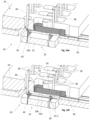
- the slide 30 At the bottom of the magazine 14 is the slide 30, an example of which is shown in the Fig. 5 to 8 and which preferably also has a shape specially adapted to the wave winding wire 10.
- the slider 30 performs at least two tasks. Firstly, it serves as a storage area, which prevents the wave winding wire 10 from accidentally falling down. Secondly, the wave winding wires 10 are separated with it. In other embodiments, the slider 30 can also be designed in such a way that the wave winding wire 10 is not placed on it, with the slider 30 only serving for separating. This is possible, for example, in that the wave winding wire 10 is pressed outwards against the guides 20 of the magazine 14 due to the inherent stress of the meandering bend. For an improved process in terms of process reliability, the slider 30 is also designed as a storage area for the wave winding wire 10, as in the embodiments shown, but preferably as described.
- the slider 30 has tooth-like projections 56 adapted to the meander shape with recesses 58 in between and step-like wire supports 60 formed thereon to form force introduction points 62.
- the force for displacement is introduced at each bend of the roof, at the front (at the respective front winding head 28a) and at the rear (at the respective rear winding head 28b). This can be done as in Fig. 5 and 6 indicated only at one point per roof (winding head 28a, 28b), but also at several points of the wave winding wire 10.
- sliders 30 can be used in the manufacturing process for the winding mat 12.
- the slider 30 can be made from one part, e.g. from a solid plate by machining or other suitable processes.
- two sheets of thin material can also be connected to one another, preferably welded, so that together they are smaller in height than one wave winding wire.
- the slider 30 is designed in height (z-direction) such that only the lowest wave winding wire 10 is moved in the magazine. The other wave winding wires 10 lying on top of one another are then held back by the magazine during separation.
- the batch process is controlled via the (in Fig. 11 and 13 indicated) control 46 of the stacking device 16, which can be part of an overall control 64 of a manufacturing device 66 for the winding mat 12.
- the controls 46, 64 are designed in particular as electronic controls with computer programs loaded therein and contain corresponding instructions for controlling the movement sequences of the devices 16, 66.
- a workpiece carrier 22 is positioned beneath the magazine 14 and then lifted out.
- the workpiece carrier 22 itself has receiving pins 50 arranged and designed accordingly depending on the wire and mat geometry. There is always a wire portion between two adjacent receiving pins 50 - in particular, the straight wire sections 26 are each placed between two adjacent receiving pins 50.
- the distance between the receiving pins 50 is selected according to the distance between the slots in the component of the electrical machine that accommodates the coil winding - in particular the laminated core of a stator.
- its longitudinal direction corresponds to the circumferential direction in the stator
- the height direction (z-direction) of the winding mat 12 corresponds to the radial direction when used in the stator
- the transverse direction (x-direction) corresponds to the axial direction when the winding mat 12 is used in the stator.
- the immersion of the receiving pins 50 of the workpiece carrier 22 positioned in the transfer position 23 into the magazine 14 creates a transfer area that allows the individual wave winding wire 10 to continue to be kept stable in its shape over the entire time.
- each wave winding wire enters the workpiece carrier 22 in a better controlled manner, in the embodiment shown it is actively pushed into the workpiece carrier 22 during the transfer, preferably with simple bolts - here the front and rear bolts 36, 38. This improves the process reliability and each wave winding wire 10 enters the workpiece carrier 22.
- the active pushing can, for example, be carried out at two or more points per Winding head 28a, 28b, but also at just one point per winding head 28a, 28b.
- the front bolts 36 also have the task of holding the wave winding wire 10 in the separated, front position - ie the storage position.
- the front bolts can be provided with a simple step as separating bolts so that the wave winding wire 10 is not pulled backwards when the slider 30 is pulled back.
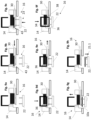
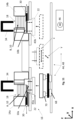
- Fig. 9a and 10a show the starting position in the preferred embodiment of the stacking method.
- Several wave winding wires 10 are provided in the magazine 14 in the receiving space 18.
- the lowermost wave winding wire 10a rests on the retracted slide 30 (or in other embodiments on the storage guide 42).
- the slider 30 then separates the lowest wave winding wire 10a.
- the slider 30 is moved from a starting position below the receiving space 18 in the transverse direction to the storage position 43 and the lowest wave winding wire 10a is taken along.
- the workpiece carrier 22 is moved to a first position 21.1, which the wave winding wire to be deposited - here initially the lowest wave winding wire 10a - is to take up in the longitudinal direction on the workpiece carrier 22 and ultimately within the winding mat 12 (see the Fig. 14a-14c ) is positioned on a first transfer position 23.
- the winding carrier 22 first takes the Fig. 10b to 10g shown longitudinal position for the first wave winding wire 10a.
- the workpiece carrier 22 is - as shown in Fig. 9c and 10c shown - especially after positioning in the longitudinal direction.
- the workpiece carrier 22 and the magazine 14 are moved relative to each other in the vertical direction (z-direction) until the workpiece carrier 22 dips into the magazine 14 and the receiving pins 50 and the guides 20 overlap each other in the vertical direction.
- the bolts 36, 38 then move into a retaining position in which they secure the wave winding wire that has been moved to the deposit position and is thus to be deposited individually - here, for example, the first wave winding wire 10a - against being moved backwards in the transverse direction.
- the lifting arrangement 34 moves downwards with the front and rear bolts 36, 38 until the step-like ends engage the front winding heads 28a of the wave winding wire 10a to be deposited.
- the front and rear bolts 36, 38 push the wave winding wire 10a to be deposited - in particular guided by the deposit guide 42 - into the workpiece carrier 22.
- the straight wire sections 26 of the wave winding wire 10a to be deposited are each received between several pairs of adjacent receiving pins 50.
- the workpiece carrier 22 is then repositioned in its longitudinal direction according to the desired second position 21.2 of the next wave winding wire 10b to be deposited.
- the workpiece carrier 22 is generally positioned relative to the magazine 14 at a second transfer position offset in the longitudinal direction from the first transfer position 23 in order to deposit another wave winding wire 10b on the workpiece carrier 22 offset from the previously deposited wave winding wire 10a using the otherwise same steps as described for the first wave winding wire 10a.
- another wave winding wire 10b is deposited in the same longitudinal position as a wave winding wire 10a deposited directly or indirectly beforehand.
- Fig. 12 and 14a-14c show different views of the workpiece carrier 22 with exemplary wire stacks.
- the stacking device 16 as shown in the Fig. 1 to 10 shown, have a single magazine 14 for stacking a winding mat 12 of similar wave winding wires 10.
- a further embodiment of the stacking device 16 is shown, which has several such magazines 14, for example at least a first magazine 14a and a second magazine 14b.
- the movement device 44 is designed to position the workpiece carrier 22, e.g. by movement in the transverse direction (x-direction), optionally at the storage position 43a of the first magazine 14a or at the storage position 43b of the second magazine 14b.
- a winding mat 12 can also be composed of differently bent individual wires - wave winding wires 10 - depending on the mat geometry - in particular the number of different individual wires, the amount of individual wires used in each case and/or the stacking sequence of the individual wires - preferably at least one magazine 14a, 14b is provided for each different individual wire geometry to be used.
- a first stack A of wave winding wires 10 with a first geometry is arranged in the first magazine 14a and a second stack B with wave winding wires 10 with a different second geometry is arranged in the second magazine 14b.
- first linear axes 68 example of actuators of the movement device 44 - (movement in the transverse direction or x-direction).
- the workpiece carrier 22 can be moved perpendicular to the direction of travel, i.e. here in the longitudinal direction or y-direction, also preferably with linear axes, here the second linear axes 70, in order to create the required distance between each individual wire with repeatable accuracy and uniformity. This means that the longitudinal positioning from the first transfer position 23 to the second transfer position can already take place during the travel between the magazines 14a, 14b.
- control 46 which is connected to the actuators of the stacking device 16, such as in particular the actuators for the stroke of the lifting arrangement 34, the actuators of the slide 30 and the actuators of the movement device 44 (for movement of the workpiece carrier 22 in the x, y and/or z direction) and is designed to control the stacking device 16 for automatically carrying out the stacking process.
- Fig. 13 shows a manufacturing device 66 for manufacturing the winding mat 12 for forming a coil winding for a stator (or for a rotor).
- the manufacturing device 66 has the stacking device 16 according to one of the previously explained embodiments (here, for example, with first and second magazines 14a, 14b) and a press 72 which is designed to stamp winding heads 28a, 28b of a stack of wave winding wires 10 formed on the workpiece carrier 22.
- the press 72 has, for example, a lower embossing die 74, an upper embossing die 76 and a joining module 78.
- the lower part 54 of the workpiece carrier 22 is designed as a lower part of the embossing die 74 or is arranged on the lower embossing die 74.
- the manufacturing device 66 has the overall control 64, which is designed to automatically control the manufacturing device 66 to carry out the manufacturing method for producing the winding mat 12. In addition to carrying out the stacking method, this also includes embossing of winding heads 28a, 28b of the wave winding wires 10a-10f already stacked on the workpiece carrier 22.
- a finished winding mat 12 therefore does not just consist of individual wires placed on top of one another.
- the wave winding wires 10, 10a-10f also have an embossing in the head area.
- the workpiece carrier 22 is designed so that the individual wires are stacked directly on the lower part 54 of an embossing die 74.
- the preferably used linear units 68, 70 allow the workpiece carrier 22 to be moved exactly to the appropriate upper embossing die 76. This makes it possible to press the winding mat 12 - in several partial steps or as a whole - regardless of how many wave winding wires 10 are in the workpiece carrier 22.
- a joining module 78 used for this purpose can carry out the pressing from below or from above. An additional advantage is that even after the pressing process, the winding mat 12 is still held in shape by the holding pins 50. This makes further workpiece transfer much easier.
- the magazine 14 can also be equipped with a hold-down device 80, which provides additional security by separating only the lowest wave winding wire 10 in the magazine.
- the hold-down device 80 can be used to press out any unevenness and the wave winding wires 10, 10a-10g lie flat on the slide 30 (or the storage guide 32).
- the hold-down device 80 can be moved, for example, by means of an actuator controlled by the control 46 in order to apply a vertical hold-down force from above to the wave winding wires arranged in the receiving space 18 of the magazine 14.
- Fig. 14a shows the workpiece carrier 22 with the first wave winding wire 10a placed thereon in the first position 21.1.
- Fig. 14b shows the workpiece carrier 22 with a winding mat 12, which comprises a first to sixth wave winding wire 10a-10f stacked on top of one another at different positions 21.1-21.6.
- Fig. 14c shows a winding mat 12, in which a seventh to twelfth wave winding wire 10g-10m is stacked on the first to sixth wave winding wire 10a-10f.
- several wave winding wires 10a, 10g can also be stacked one on top of the other in the longitudinal direction at the same position 21.1.
- the second and eighth wave winding wires 10b, 10h lie one on top of the other at the second position 21.2, etc.
Landscapes
- Engineering & Computer Science (AREA)
- Manufacturing & Machinery (AREA)
- Power Engineering (AREA)
- Mechanical Engineering (AREA)
- Windings For Motors And Generators (AREA)
- Manufacture Of Motors, Generators (AREA)
Claims (14)
- Procédé d'empilage de fils d'enroulement ondulés (10, 10a-10f) pour former un tapis d'enroulement (12) pour l'enroulement d'une bobine d'un stator, ledit procédé d'empilage comprenant les étapes suivantes:fournir au moins un magasin (14, 14a, 14b) contenant une pluralité de fils d'enroulement ondulés similaires (10) dans un espace de réception (18), dans lequel le magasin (14, 14a, 14b) est conçu comme un magasin de chute de sorte que l'espace de réception (18) s'étend, avec au moins une composante directionnelle, dans une direction verticale à travers le magasin (14, 14a, 14b), dans lequel le contour de l'espace de réception (18) est adapté aux fils d'enroulement ondulés reçus (10), de sorte que les fils d'enroulement ondulés (10) sont positionnés sur une pluralité de dispositifs de guidage (20) à différents endroits de la délimitation de l'espace de réception (18) et sont guidés à travers l'espace de réception (18) sans modification de leur géométrie,positionner un porte-pièce (22) pourvu d'une structure de retenue (24) pour un tapis d'enroulement (12) formé d'une pluralité de fils d'enroulement ondulés empilés (10, 10a-10f) dans une première position de transfert (23) en dessous d'au moins un magasin (14, 14a, 14b) et déposer un fil d'enroulement ondulé (10) dudit au moins un magasin (14, 14a, 14b) à une première position (21.1) sur le porte-pièce, positionner le porte-pièce (22) dans une deuxième position de transfert décalée par rapport à la première position de transfert (23) sous ledit au moins un magasin (14, 14a, 14b), et déposer un autre fil d'enroulement ondulé (10) dudit au mois un magasin (14, 14a, 14b) à une position (21.2, 21.2, 21.3) décalée par rapport à la première position (21.1) sur le porte-pièce (22).
- Procédé d'empilage selon la revendication 1, caractérisé parfournir une pluralité de magasins (14a, 14b) contenant chacun des fils d'enroulement ondulés (10) de formes différentes avec des espaces de réception respectifs (18) adaptés à ceux-ci,positionner le porte-pièce (22) sur un premier (14a) des magasins et déposer un premier fil d'enroulement ondulé (10a) du premier magasin (14a) à la première position sur le porte-pièce (22) et positionner le porte-pièce (22) sur un deuxième (14b) des magasins et déposer un deuxième fil d'enroulement ondulé (10b) du deuxième magasin (14b) à la deuxième position sur le porte-pièce (22).
- Procédé d'empilage selon l'une quelconque des revendications précédentes, caractérisé en ce que le dépôt comprend au moins une ou plusieurs des étapes suivantes:3.1 séparer le fil d'enroulement ondulé (10a) le plus bas à déposer du magasin (14, 14a, 14b) au moyen d'un dispositif de séparation (29) qui déplace le fil d'enroulement ondulé (10) à déposer de l'espace de réception (18) vers une position de dépôt (43), le fil d'enroulement ondulé (10) étant retenu et/ou guidé pendant le déplacement de manière à maintenir sa géométrie;3.2 alimenter successivement des fils d'enroulement ondulés (10) dans l'espace de réception (18) dans une direction verticale vers le bas;3.3 guider les fils d'enroulement ondulés (10) dans l'espace de réception (18) de manière à maintenir leur géométrie;3.4 appliquer une force verticale aux fils d'enroulement ondulés (10) disposés dans l'espace de réception (18) par le haut afin de guider les fils d'enroulement ondulés (10) et/ou de les positionner dans l'espace de réception (18) dans la direction verticale et/ou de les presser contre un support prévu dans la zone inférieure;3.5 utiliser un poussoir (30), qui peut être déplacé transversalement à la direction longitudinale des fils d'enroulement ondulés (10), comme support pour empêcher les fils d'enroulement ondulés(10) de tomber hors de l'espace de réception (18) de manière involontaire et/ou comme dispositif de séparation (29);3.6 insérer activement le fil d'enroulement ondulé (10) à déposer dans les structures de retenue (24) au moyen d'éléments d'insertion (35, 38) déplacés dans le sens vertical.
- Procédé d'empilage selon l'une quelconque des revendications précédentes, caractérisé en ce que le positionnement comprend au moins une ou plusieurs des étapes suivantes:4.1 positionner la structure de retenue (24) dans la direction transversale qui s'étend transversalement à l'extension longitudinale des fils d'enroulement ondulés (10) reçus dans l'espace de réception (18) à une position de dépôt (43) décalée dans la direction transversale par rapport à l'espace de réception (18);4.2 positionner le porte-pièce (22) dans la direction longitudinale qui s'étend dans la direction de l'extension longitudinale des fils d'enroulement ondulés (10) reçus dans l'espace de réception (18) à une position de transfert décalée longitudinalement par rapport à une position de transfert précédente (23);4.3. positionner le porte-pièce (22) dans la direction verticale à la position de transfert (23) de telle sorte que les structures de retenue (22) se chevauchent verticalement avec les dispositifs de guidage (20, 42) du magasin (14).
- Procédé de fabrication d'un tapis d'enroulement (12) pour l'enroulement d'une bobine d'un stator, comprenant l'exécution du procédé d'empilage selon l'une quelconque des revendications précédentes pour obtenir une pile de fils d'enroulement ondulés (10, 10a-10f), dans lequel des têtes d'enroulement en pile (28a, 28b) sont disposées des deux côtés, et le gaufrage de la pile sur le support de pièce (22) dans la zone des têtes d'enroulement (28a, 28b).
- Magasin (14, 14a, 14b) destiné à être utilisé dans le procédé d'empilage selon l'une quelconque des revendications précédentes, comprenant:un espace de réception (18) en forme de méandre pour une pluralité de fils d'enroulement ondulés similaires (10) avec des dispositifs de guidage latéraux (20) pour guider exactement et positionner latéralement les fils d'enroulement ondulés (10) sans tension, de sorte que les fils d'enroulement ondulés (10) sont guidés à travers l'espace de réception (18) sans modifier leur géométrie, dans lequel le magasin (14, 14a, 14b) est conçu comme un magasin de chute, de sorte que l'espace de réception (18) s'étend, avec au moins une composante directionnelle, verticalement à travers le magasin (14, 14a, 14b);un dispositif de guidage de dépôt (42) pour déposer un fil d'enroulement ondulé (10) à une position de dépôt (43) décalée par rapport à l'espace de réception (18) dans une direction transversale s'étendant transversalement à l'extension longitudinale de l'espace de réception en forme de méandre (18), et une cavité de réception (52.1, 52.2) pour recevoir un porte-pièce (22) avec une structure de retenue (24) plongeant dans le magasin (14, 14a, 14b) par le bas.
- Magasin (14, 14a, 14b) selon la revendication 6, caractérisé en ce que l'espace de réception (18) est formé par une délimitation d'une pluralité de parties de magasin segmentées et interchangeables (14.1, 14.2).
- Magasin (14, 14a, 14b) selon la revendication 6 ou 7, caractérisé par8.1 un dispositif de séparation (29) pour déplacer latéralement le fil d'enroulement le plus bas (10) de l'espace de réception (18) à la position de dépôt (43) avec des points d'application de force (62) configurés pour maintenir la géométrie du fil d'enroulement (10);8.2 un poussoir (30) mobile dans le sens transversal comme support pour empêcher les fils d'enroulement ondulés(10) de tomber de l'espace de réception (18) vers le bas et/ou pour séparer le fil d'enroulement ondulé le plus bas (10) par déplacement latéral de l'espace de réception (18) vers la position de dépôt (43).
- Dispositif d'empilage (16) pour la mise en oeuvre du procédé d'empilage selon l'une quelconque des revendications 1 à 5, comprenant:au moins un magasin (14, 14a, 14b) selon l'une quelconque des revendications 6 à 8,au moins un porte-pièce (22) comportant une structure de retenue (24) pour la pile de fils d'enroulement ondulés déposée (10, 10a-10f),au moins un dispositif de positionnement (48) pour le positionnement relatif du porte-pièce (22) et d'au moins un magasin (14, 14a, 14b) à des positions de transfert prédéterminées (23);au moins un dispositif de déplacement (44) pour déplacer relativement le porte-pièce (22) et au moins un magasin (14, 14a, 14b); etune unité de commande (46) adaptée pour commander le dispositif d'empilage (16) afin d'exécuter automatiquement le procédé d'empilage selon l'une quelconque des revendications 1 à 5.
- Dispositif d'empilage (16) selon la revendication 9, caractérisé pardes éléments d'insertion (34, 36, 38) pour insérer activement le fil d'enroulement ondulé (10) à déposer dans la structure de retenue (24) et/ouun abaisseur (80) pour exercer une force verticale sur les fils d'enroulement ondulés (10) dans l'espace de réception (18).
- Dispositif d'empilage (16) selon la revendication 9 ou 10, caractérisé par
un premier magasin (14a) selon l'une quelconque des revendications 6 à 8 pour recevoir les premiers fils d'enroulement ondulés (10a) et un second magasin (14b) selon l'une quelconque des revendications 6 à 8 ayant un espace de réception (18) aux contours différents pour recevoir les seconds fils d'enroulement ondulés (10b) différents des premiers fils d'enroulement à ondes (10a), dans lequel le dispositif de déplacement (44) est conçu pour déplacer le porte-pièce (22) entre les positions de dépôt (43a, 43b) du premier et du second magasin (14a, 14b) avec un déplacement différent dans la direction longitudinale. - Unité de commande (46) pour un dispositif d'empilage (16) selon l'une quelconque des revendications 9 à 11, dans laquelle l'unité de commande (46) est adaptée pour commander le dispositif d'empilage (16) afin d'exécuter le procédé d'empilage selon l'une quelconque des revendications 1 à 5.
- Programme d'ordinateur comprenant des instructions de commande pour amener un dispositif d'empilage (16) selon l'une quelconque des revendications 9 à 11 à exécuter le procédé d'empilage selon l'une quelconque des revendications 1 à 5.
- Dispositif de fabrication (66) d'un tapis d'enroulement (12) pour le bobinage d'un stator, comprenant un dispositif d'empilage (16) selon l'une quelconque des revendications 9 à 11 et une presse (72) apte à embosser, sur le porte-pièce (22), les têtes d'enroulement (28a, 28b) d'une pile de fils d'enroulement ondulés (10, 10a-10f) formée sur le porte-pièce (22).
Priority Applications (2)
| Application Number | Priority Date | Filing Date | Title |
|---|---|---|---|
| US18/356,641 US20240030792A1 (en) | 2022-07-22 | 2023-07-21 | Stacking method for stacking wave winding wires, magazine for use therein and uses thereof |
| CN202310901235.7A CN117439354A (zh) | 2022-07-22 | 2023-07-21 | 堆叠波形绕组线的堆叠方法、方法中使用的料仓及其用途 |
Applications Claiming Priority (1)
| Application Number | Priority Date | Filing Date | Title |
|---|---|---|---|
| DE102022118399 | 2022-07-22 |
Publications (3)
| Publication Number | Publication Date |
|---|---|
| EP4311087A1 EP4311087A1 (fr) | 2024-01-24 |
| EP4311087B1 true EP4311087B1 (fr) | 2024-07-17 |
| EP4311087C0 EP4311087C0 (fr) | 2024-07-17 |
Family
ID=83900020
Family Applications (1)
| Application Number | Title | Priority Date | Filing Date |
|---|---|---|---|
| EP22202369.9A Active EP4311087B1 (fr) | 2022-07-22 | 2022-10-19 | Procédé d'empilage pour empiler des fils enroulés sur des arbres, magasin pour utilisation dans ce procédé et utilisations de celui-ci |
Country Status (4)
| Country | Link |
|---|---|
| US (1) | US20240030792A1 (fr) |
| EP (1) | EP4311087B1 (fr) |
| CN (1) | CN117439354A (fr) |
| HU (1) | HUE068593T2 (fr) |
Family Cites Families (4)
| Publication number | Priority date | Publication date | Assignee | Title |
|---|---|---|---|---|
| JP4461399B2 (ja) * | 2008-03-05 | 2010-05-12 | 株式会社デンソー | 回転電機用コイル組立体の編込み機 |
| US9071116B2 (en) * | 2013-01-17 | 2015-06-30 | Remy Technologies, Llc | Apparatus for installing stator winding conductors |
| EP3906607B1 (fr) * | 2019-03-05 | 2022-05-04 | Grob-Werke GmbH & Co. KG | Procédé de cintrage, procédé de fabrication, dispositif de cintrage et dispositif de fabrication pour un tapis d'enroulement ondulé ainsi que tapis d'enroulement ondulé obtenu avec ce procédé |
| EP4002533B1 (fr) * | 2020-11-16 | 2023-06-14 | Grob-Werke GmbH & Co. KG | Dispositif et procédé d'empilage des composants de pile et dispositif et procédé de fabrication d'une structure en couche de pile à combustible |
-
2022
- 2022-10-19 EP EP22202369.9A patent/EP4311087B1/fr active Active
- 2022-10-19 HU HUE22202369A patent/HUE068593T2/hu unknown
-
2023
- 2023-07-21 US US18/356,641 patent/US20240030792A1/en active Pending
- 2023-07-21 CN CN202310901235.7A patent/CN117439354A/zh active Pending
Also Published As
| Publication number | Publication date |
|---|---|
| CN117439354A (zh) | 2024-01-23 |
| HUE068593T2 (hu) | 2025-01-28 |
| EP4311087A1 (fr) | 2024-01-24 |
| US20240030792A1 (en) | 2024-01-25 |
| EP4311087C0 (fr) | 2024-07-17 |
Similar Documents
| Publication | Publication Date | Title |
|---|---|---|
| DE102018114875A1 (de) | Vorrichtung und Verfahren zur Herstellung eines mit Wicklungen versehenen Maschinenelements für eine elektrische Maschine | |
| EP3906607B1 (fr) | Procédé de cintrage, procédé de fabrication, dispositif de cintrage et dispositif de fabrication pour un tapis d'enroulement ondulé ainsi que tapis d'enroulement ondulé obtenu avec ce procédé | |
| EP3463708B1 (fr) | Système de stockage d'outils, installation de fabrication et procédé de manipulation comprenant un système de stockage d'outils de ce type | |
| EP3759795A1 (fr) | Tapis d'enroulement et tapis à bobines comprenant celui-ci ainsi qu'un composant d'une machine électrique ainsi formé et son procédé de fabrication | |
| DE69518130T2 (de) | Zuführvorrichtung für Klemmen und Krimpwerkzeuge und deren Herstellungsverfahren | |
| WO2005002027A2 (fr) | Procede et dispositif pour introduire des enroulements ondules dans des empilements de plaques de rotor et de stator de machines electriques | |
| EP3863161A1 (fr) | Dispositif d'assemblage et système comprenant un dispositif d'assemblage et un rotor | |
| AT520207B1 (de) | Verfahren und Vorrichtung zum positionierten Halten eines Blechpakets mitsamt darin aufgenommenen Leiterelementen | |
| EP3663015B1 (fr) | Machine de fabrication d'éléments de fil | |
| EP2660836A2 (fr) | Installation d'empilement de noyaux de transformateurs et procédé de son fonctionnement | |
| DE2716330B2 (de) | Verfahren zur Bestückung von Schaltungsplatinen mit plättchenförmigen Schaltungsbauteilen und Vorrichtung zur Durchführung des Verfahrens | |
| DE102022214312A1 (de) | Batteriepackmontagevorrichtung und verfahren | |
| WO2019040957A1 (fr) | Procédé et dispositif de maintien positionné d'un paquet de tôles et des éléments conducteurs logés dans celui-ci | |
| EP0523270A1 (fr) | Méthode pour commander un système de positionnement | |
| EP4184766A1 (fr) | Procédé et dispositif de fabrication d'une nappe d'enroulement tissée pour un enroulement de bobine d'une machine électrique | |
| EP4175139A1 (fr) | Dispositif et procédé de fabrication d'une flexion d'un enroulement ondulé pour un enroulement de bobine d'une machine électrique | |
| DE19848009C2 (de) | Verfahren zum Herstellen einer Leiterschleife mit angeschlossenem Chipmodul zur Verwendung in kontaktlosen Chipkarten sowie Trägervorrichtung zur Verwendung in dem Verfahren sowie kontaktlose Chipkarte | |
| WO2007017380A1 (fr) | Procede pour realiser un enroulement dans une machine electrique, et corps d'assistance a l'enroulement | |
| EP4311087A1 (fr) | Procédé d'empilage pour empiler des fils enroulés sur des arbres, magasin pour utilisation dans ce procédé et utilisations de celui-ci | |
| EP3453470A1 (fr) | Dispositif de transport pour barres ou fils | |
| EP4007053A2 (fr) | Dispositif d'assemblage et procédé de fourniture d'un module de batterie | |
| EP4213353A1 (fr) | Dispositif et procédé de fabrication d'un enroulement ondulé inséré | |
| DE102022201430B4 (de) | Stapelvorrichtung zum Stapeln von Dünnschichtelementen, insbesondere zum Stapeln von plattenförmigen Membran-Elektrodeneinheiten (MEA) und Bipolarplatten (BPP) einer Brennstoffzelle | |
| DE102022130543A1 (de) | Verfahren zum Tausch von Leitern bei der Herstellung einer flachen Wellenwicklung | |
| DE1237189B (de) | Verfahren und Einrichtung zur Herstellung von elektronischen Bausteinen |
Legal Events
| Date | Code | Title | Description |
|---|---|---|---|
| PUAI | Public reference made under article 153(3) epc to a published international application that has entered the european phase |
Free format text: ORIGINAL CODE: 0009012 |
|
| STAA | Information on the status of an ep patent application or granted ep patent |
Free format text: STATUS: REQUEST FOR EXAMINATION WAS MADE |
|
| 17P | Request for examination filed |
Effective date: 20230804 |
|
| AK | Designated contracting states |
Kind code of ref document: A1 Designated state(s): AL AT BE BG CH CY CZ DE DK EE ES FI FR GB GR HR HU IE IS IT LI LT LU LV MC ME MK MT NL NO PL PT RO RS SE SI SK SM TR |
|
| GRAP | Despatch of communication of intention to grant a patent |
Free format text: ORIGINAL CODE: EPIDOSNIGR1 |
|
| STAA | Information on the status of an ep patent application or granted ep patent |
Free format text: STATUS: GRANT OF PATENT IS INTENDED |
|
| INTG | Intention to grant announced |
Effective date: 20240229 |
|
| GRAS | Grant fee paid |
Free format text: ORIGINAL CODE: EPIDOSNIGR3 |
|
| GRAA | (expected) grant |
Free format text: ORIGINAL CODE: 0009210 |
|
| STAA | Information on the status of an ep patent application or granted ep patent |
Free format text: STATUS: THE PATENT HAS BEEN GRANTED |
|
| AK | Designated contracting states |
Kind code of ref document: B1 Designated state(s): AL AT BE BG CH CY CZ DE DK EE ES FI FR GB GR HR HU IE IS IT LI LT LU LV MC ME MK MT NL NO PL PT RO RS SE SI SK SM TR |
|
| REG | Reference to a national code |
Ref country code: CH Ref legal event code: EP |
|
| REG | Reference to a national code |
Ref country code: DE Ref legal event code: R096 Ref document number: 502022001250 Country of ref document: DE |
|
| REG | Reference to a national code |
Ref country code: IE Ref legal event code: FG4D Free format text: LANGUAGE OF EP DOCUMENT: GERMAN |
|
| U01 | Request for unitary effect filed |
Effective date: 20240724 |
|
| U07 | Unitary effect registered |
Designated state(s): AT BE BG DE DK EE FI FR IT LT LU LV MT NL PT SE SI Effective date: 20240812 |
|
| U20 | Renewal fee for the european patent with unitary effect paid |
Year of fee payment: 3 Effective date: 20241028 |
|
| PG25 | Lapsed in a contracting state [announced via postgrant information from national office to epo] |
Ref country code: NO Free format text: LAPSE BECAUSE OF FAILURE TO SUBMIT A TRANSLATION OF THE DESCRIPTION OR TO PAY THE FEE WITHIN THE PRESCRIBED TIME-LIMIT Effective date: 20241017 |
|
| PG25 | Lapsed in a contracting state [announced via postgrant information from national office to epo] |
Ref country code: GR Free format text: LAPSE BECAUSE OF FAILURE TO SUBMIT A TRANSLATION OF THE DESCRIPTION OR TO PAY THE FEE WITHIN THE PRESCRIBED TIME-LIMIT Effective date: 20241018 Ref country code: PL Free format text: LAPSE BECAUSE OF FAILURE TO SUBMIT A TRANSLATION OF THE DESCRIPTION OR TO PAY THE FEE WITHIN THE PRESCRIBED TIME-LIMIT Effective date: 20240717 |
|
| PG25 | Lapsed in a contracting state [announced via postgrant information from national office to epo] |
Ref country code: IS Free format text: LAPSE BECAUSE OF FAILURE TO SUBMIT A TRANSLATION OF THE DESCRIPTION OR TO PAY THE FEE WITHIN THE PRESCRIBED TIME-LIMIT Effective date: 20241117 |
|
| PG25 | Lapsed in a contracting state [announced via postgrant information from national office to epo] |
Ref country code: HR Free format text: LAPSE BECAUSE OF FAILURE TO SUBMIT A TRANSLATION OF THE DESCRIPTION OR TO PAY THE FEE WITHIN THE PRESCRIBED TIME-LIMIT Effective date: 20240717 |
|
| PG25 | Lapsed in a contracting state [announced via postgrant information from national office to epo] |
Ref country code: ES Free format text: LAPSE BECAUSE OF FAILURE TO SUBMIT A TRANSLATION OF THE DESCRIPTION OR TO PAY THE FEE WITHIN THE PRESCRIBED TIME-LIMIT Effective date: 20240717 Ref country code: RS Free format text: LAPSE BECAUSE OF FAILURE TO SUBMIT A TRANSLATION OF THE DESCRIPTION OR TO PAY THE FEE WITHIN THE PRESCRIBED TIME-LIMIT Effective date: 20241017 |
|
| REG | Reference to a national code |
Ref country code: HU Ref legal event code: AG4A Ref document number: E068593 Country of ref document: HU |
|
| PG25 | Lapsed in a contracting state [announced via postgrant information from national office to epo] |
Ref country code: RS Free format text: LAPSE BECAUSE OF FAILURE TO SUBMIT A TRANSLATION OF THE DESCRIPTION OR TO PAY THE FEE WITHIN THE PRESCRIBED TIME-LIMIT Effective date: 20241017 Ref country code: PL Free format text: LAPSE BECAUSE OF FAILURE TO SUBMIT A TRANSLATION OF THE DESCRIPTION OR TO PAY THE FEE WITHIN THE PRESCRIBED TIME-LIMIT Effective date: 20240717 Ref country code: NO Free format text: LAPSE BECAUSE OF FAILURE TO SUBMIT A TRANSLATION OF THE DESCRIPTION OR TO PAY THE FEE WITHIN THE PRESCRIBED TIME-LIMIT Effective date: 20241017 Ref country code: IS Free format text: LAPSE BECAUSE OF FAILURE TO SUBMIT A TRANSLATION OF THE DESCRIPTION OR TO PAY THE FEE WITHIN THE PRESCRIBED TIME-LIMIT Effective date: 20241117 Ref country code: HR Free format text: LAPSE BECAUSE OF FAILURE TO SUBMIT A TRANSLATION OF THE DESCRIPTION OR TO PAY THE FEE WITHIN THE PRESCRIBED TIME-LIMIT Effective date: 20240717 Ref country code: GR Free format text: LAPSE BECAUSE OF FAILURE TO SUBMIT A TRANSLATION OF THE DESCRIPTION OR TO PAY THE FEE WITHIN THE PRESCRIBED TIME-LIMIT Effective date: 20241018 Ref country code: ES Free format text: LAPSE BECAUSE OF FAILURE TO SUBMIT A TRANSLATION OF THE DESCRIPTION OR TO PAY THE FEE WITHIN THE PRESCRIBED TIME-LIMIT Effective date: 20240717 |
|
| PG25 | Lapsed in a contracting state [announced via postgrant information from national office to epo] |
Ref country code: SM Free format text: LAPSE BECAUSE OF FAILURE TO SUBMIT A TRANSLATION OF THE DESCRIPTION OR TO PAY THE FEE WITHIN THE PRESCRIBED TIME-LIMIT Effective date: 20240717 |
|
| PG25 | Lapsed in a contracting state [announced via postgrant information from national office to epo] |
Ref country code: CZ Free format text: LAPSE BECAUSE OF FAILURE TO SUBMIT A TRANSLATION OF THE DESCRIPTION OR TO PAY THE FEE WITHIN THE PRESCRIBED TIME-LIMIT Effective date: 20240717 |
|
| PG25 | Lapsed in a contracting state [announced via postgrant information from national office to epo] |
Ref country code: SK Free format text: LAPSE BECAUSE OF FAILURE TO SUBMIT A TRANSLATION OF THE DESCRIPTION OR TO PAY THE FEE WITHIN THE PRESCRIBED TIME-LIMIT Effective date: 20240717 |
|
| PLBE | No opposition filed within time limit |
Free format text: ORIGINAL CODE: 0009261 |
|
| STAA | Information on the status of an ep patent application or granted ep patent |
Free format text: STATUS: NO OPPOSITION FILED WITHIN TIME LIMIT |
|
| 26N | No opposition filed |
Effective date: 20250422 |
|
| PG25 | Lapsed in a contracting state [announced via postgrant information from national office to epo] |
Ref country code: MC Free format text: LAPSE BECAUSE OF FAILURE TO SUBMIT A TRANSLATION OF THE DESCRIPTION OR TO PAY THE FEE WITHIN THE PRESCRIBED TIME-LIMIT Effective date: 20240717 |
|
| PG25 | Lapsed in a contracting state [announced via postgrant information from national office to epo] |
Ref country code: IE Free format text: LAPSE BECAUSE OF NON-PAYMENT OF DUE FEES Effective date: 20241019 |
|
| PG25 | Lapsed in a contracting state [announced via postgrant information from national office to epo] |
Ref country code: RO Free format text: LAPSE BECAUSE OF FAILURE TO SUBMIT A TRANSLATION OF THE DESCRIPTION OR TO PAY THE FEE WITHIN THE PRESCRIBED TIME-LIMIT Effective date: 20240717 |
|
| U20 | Renewal fee for the european patent with unitary effect paid |
Year of fee payment: 4 Effective date: 20251027 |
|
| PG25 | Lapsed in a contracting state [announced via postgrant information from national office to epo] |
Ref country code: CY Free format text: LAPSE BECAUSE OF FAILURE TO SUBMIT A TRANSLATION OF THE DESCRIPTION OR TO PAY THE FEE WITHIN THE PRESCRIBED TIME-LIMIT; INVALID AB INITIO Effective date: 20221019 |
|
| PGFP | Annual fee paid to national office [announced via postgrant information from national office to epo] |
Ref country code: HU Payment date: 20251016 Year of fee payment: 4 |