EP4311216A1 - Bilderzeugungsvorrichtung, steuerungsverfahren zur steuerung der bilderzeugungsvorrichtung und speichermedium - Google Patents
Bilderzeugungsvorrichtung, steuerungsverfahren zur steuerung der bilderzeugungsvorrichtung und speichermedium Download PDFInfo
- Publication number
- EP4311216A1 EP4311216A1 EP23185887.9A EP23185887A EP4311216A1 EP 4311216 A1 EP4311216 A1 EP 4311216A1 EP 23185887 A EP23185887 A EP 23185887A EP 4311216 A1 EP4311216 A1 EP 4311216A1
- Authority
- EP
- European Patent Office
- Prior art keywords
- image data
- color mode
- color
- mode
- forming apparatus
- Prior art date
- Legal status (The legal status is an assumption and is not a legal conclusion. Google has not performed a legal analysis and makes no representation as to the accuracy of the status listed.)
- Granted
Links
Images


Classifications
-
- H—ELECTRICITY
- H04—ELECTRIC COMMUNICATION TECHNIQUE
- H04N—PICTORIAL COMMUNICATION, e.g. TELEVISION
- H04N1/00—Scanning, transmission or reproduction of documents or the like, e.g. facsimile transmission; Details thereof
- H04N1/23—Reproducing arrangements
- H04N1/2307—Circuits or arrangements for the control thereof, e.g. using a programmed control device, according to a measured quantity
- H04N1/2369—Selecting a particular reproducing mode from amongst a plurality of modes, e.g. paper saving or normal, or simplex or duplex
-
- G—PHYSICS
- G03—PHOTOGRAPHY; CINEMATOGRAPHY; ANALOGOUS TECHNIQUES USING WAVES OTHER THAN OPTICAL WAVES; ELECTROGRAPHY; HOLOGRAPHY
- G03G—ELECTROGRAPHY; ELECTROPHOTOGRAPHY; MAGNETOGRAPHY
- G03G15/00—Apparatus for electrographic processes using a charge pattern
- G03G15/50—Machine control of apparatus for electrographic processes using a charge pattern, e.g. regulating differents parts of the machine, multimode copiers, microprocessor control
-
- G—PHYSICS
- G03—PHOTOGRAPHY; CINEMATOGRAPHY; ANALOGOUS TECHNIQUES USING WAVES OTHER THAN OPTICAL WAVES; ELECTROGRAPHY; HOLOGRAPHY
- G03G—ELECTROGRAPHY; ELECTROPHOTOGRAPHY; MAGNETOGRAPHY
- G03G15/00—Apparatus for electrographic processes using a charge pattern
- G03G15/01—Apparatus for electrographic processes using a charge pattern for producing multicoloured copies
-
- G—PHYSICS
- G06—COMPUTING OR CALCULATING; COUNTING
- G06F—ELECTRIC DIGITAL DATA PROCESSING
- G06F3/00—Input arrangements for transferring data to be processed into a form capable of being handled by the computer; Output arrangements for transferring data from processing unit to output unit, e.g. interface arrangements
- G06F3/12—Digital output to print unit, e.g. line printer, chain printer
- G06F3/1201—Dedicated interfaces to print systems
- G06F3/1202—Dedicated interfaces to print systems specifically adapted to achieve a particular effect
- G06F3/1218—Reducing or saving of used resources, e.g. avoiding waste of consumables or improving usage of hardware resources
- G06F3/1219—Reducing or saving of used resources, e.g. avoiding waste of consumables or improving usage of hardware resources with regard to consumables, e.g. ink, toner, paper
-
- G—PHYSICS
- G06—COMPUTING OR CALCULATING; COUNTING
- G06F—ELECTRIC DIGITAL DATA PROCESSING
- G06F3/00—Input arrangements for transferring data to be processed into a form capable of being handled by the computer; Output arrangements for transferring data from processing unit to output unit, e.g. interface arrangements
- G06F3/12—Digital output to print unit, e.g. line printer, chain printer
- G06F3/1201—Dedicated interfaces to print systems
- G06F3/1223—Dedicated interfaces to print systems specifically adapted to use a particular technique
- G06F3/1237—Print job management
- G06F3/1242—Image or content composition onto a page
-
- G—PHYSICS
- G06—COMPUTING OR CALCULATING; COUNTING
- G06F—ELECTRIC DIGITAL DATA PROCESSING
- G06F3/00—Input arrangements for transferring data to be processed into a form capable of being handled by the computer; Output arrangements for transferring data from processing unit to output unit, e.g. interface arrangements
- G06F3/12—Digital output to print unit, e.g. line printer, chain printer
- G06F3/1201—Dedicated interfaces to print systems
- G06F3/1223—Dedicated interfaces to print systems specifically adapted to use a particular technique
- G06F3/1237—Print job management
- G06F3/125—Page layout or assigning input pages onto output media, e.g. imposition
- G06F3/1251—Page layout or assigning input pages onto output media, e.g. imposition for continuous media, e.g. web media, rolls
-
- G—PHYSICS
- G06—COMPUTING OR CALCULATING; COUNTING
- G06F—ELECTRIC DIGITAL DATA PROCESSING
- G06F3/00—Input arrangements for transferring data to be processed into a form capable of being handled by the computer; Output arrangements for transferring data from processing unit to output unit, e.g. interface arrangements
- G06F3/12—Digital output to print unit, e.g. line printer, chain printer
- G06F3/1201—Dedicated interfaces to print systems
- G06F3/1223—Dedicated interfaces to print systems specifically adapted to use a particular technique
- G06F3/1237—Print job management
- G06F3/1253—Configuration of print job parameters, e.g. using UI at the client
- G06F3/1254—Automatic configuration, e.g. by driver
-
- G—PHYSICS
- G06—COMPUTING OR CALCULATING; COUNTING
- G06F—ELECTRIC DIGITAL DATA PROCESSING
- G06F3/00—Input arrangements for transferring data to be processed into a form capable of being handled by the computer; Output arrangements for transferring data from processing unit to output unit, e.g. interface arrangements
- G06F3/12—Digital output to print unit, e.g. line printer, chain printer
- G06F3/1201—Dedicated interfaces to print systems
- G06F3/1223—Dedicated interfaces to print systems specifically adapted to use a particular technique
- G06F3/1237—Print job management
- G06F3/126—Job scheduling, e.g. queuing, determine appropriate device
- G06F3/1262—Job scheduling, e.g. queuing, determine appropriate device by grouping or ganging jobs
-
- G—PHYSICS
- G06—COMPUTING OR CALCULATING; COUNTING
- G06F—ELECTRIC DIGITAL DATA PROCESSING
- G06F3/00—Input arrangements for transferring data to be processed into a form capable of being handled by the computer; Output arrangements for transferring data from processing unit to output unit, e.g. interface arrangements
- G06F3/12—Digital output to print unit, e.g. line printer, chain printer
- G06F3/1201—Dedicated interfaces to print systems
- G06F3/1223—Dedicated interfaces to print systems specifically adapted to use a particular technique
- G06F3/1237—Print job management
- G06F3/1267—Job repository, e.g. non-scheduled jobs, delay printing
-
- G—PHYSICS
- G06—COMPUTING OR CALCULATING; COUNTING
- G06F—ELECTRIC DIGITAL DATA PROCESSING
- G06F3/00—Input arrangements for transferring data to be processed into a form capable of being handled by the computer; Output arrangements for transferring data from processing unit to output unit, e.g. interface arrangements
- G06F3/12—Digital output to print unit, e.g. line printer, chain printer
- G06F3/1201—Dedicated interfaces to print systems
- G06F3/1278—Dedicated interfaces to print systems specifically adapted to adopt a particular infrastructure
- G06F3/1282—High volume printer device
-
- H—ELECTRICITY
- H04—ELECTRIC COMMUNICATION TECHNIQUE
- H04N—PICTORIAL COMMUNICATION, e.g. TELEVISION
- H04N1/00—Scanning, transmission or reproduction of documents or the like, e.g. facsimile transmission; Details thereof
- H04N1/387—Composing, repositioning or otherwise geometrically modifying originals
- H04N1/3872—Repositioning or masking
- H04N1/3873—Repositioning or masking defined only by a limited number of coordinate points or parameters, e.g. corners, centre; for trimming
-
- H—ELECTRICITY
- H04—ELECTRIC COMMUNICATION TECHNIQUE
- H04N—PICTORIAL COMMUNICATION, e.g. TELEVISION
- H04N1/00—Scanning, transmission or reproduction of documents or the like, e.g. facsimile transmission; Details thereof
- H04N1/46—Colour picture communication systems
-
- G—PHYSICS
- G06—COMPUTING OR CALCULATING; COUNTING
- G06F—ELECTRIC DIGITAL DATA PROCESSING
- G06F3/00—Input arrangements for transferring data to be processed into a form capable of being handled by the computer; Output arrangements for transferring data from processing unit to output unit, e.g. interface arrangements
- G06F3/12—Digital output to print unit, e.g. line printer, chain printer
- G06F3/1201—Dedicated interfaces to print systems
- G06F3/1202—Dedicated interfaces to print systems specifically adapted to achieve a particular effect
- G06F3/1203—Improving or facilitating administration, e.g. print management
- G06F3/1208—Improving or facilitating administration, e.g. print management resulting in improved quality of the output result, e.g. print layout, colours, workflows, print preview
-
- G—PHYSICS
- G06—COMPUTING OR CALCULATING; COUNTING
- G06F—ELECTRIC DIGITAL DATA PROCESSING
- G06F3/00—Input arrangements for transferring data to be processed into a form capable of being handled by the computer; Output arrangements for transferring data from processing unit to output unit, e.g. interface arrangements
- G06F3/12—Digital output to print unit, e.g. line printer, chain printer
- G06F3/1201—Dedicated interfaces to print systems
- G06F3/1202—Dedicated interfaces to print systems specifically adapted to achieve a particular effect
- G06F3/1211—Improving printing performance
Definitions
- the present invention relates to an image forming apparatus, a control method for controlling an image forming apparatus, and a storage medium.
- an image forming apparatus such as a printer or a copying machine, that temporarily stores image data received from a host apparatus in a non-volatile memory, such as a hard disk, built into the image forming apparatus.
- the image forming apparatus appropriately reads the image data stored in the non-volatile memory, and prints out the image data.
- image forming apparatuses of this type in the form of a large-format printer that prints image data using a large sheet to print a poster.
- the large-format printer uses a roll of paper as a sheet and normally prints image data by arranging the image data in the conveying direction (e.g., the vertical direction) of the sheet.
- a roll of paper having a width that is very large relative to the width of the image data is used in such an image forming apparatus, nothing is printed from the end of the printed image to the end of the sheet in the main scanning direction (e.g., the horizontal direction) of the sheet orthogonal to the conveying direction of the sheet, which leads to a waste of the sheet.
- the apparatus it is known to operate the apparatus according to a function called nesting printing in which a plurality of pieces of image data are stored in a non-volatile memory, such as a hard disk, and placed in the main scanning direction (e.g., the horizontal direction) of the sheet.
- the image forming apparatus waits to receive the next image data and waits for printing until the width of the sheet is filled with pieces of image data in the main scanning direction of the sheet. If, however, the image forming apparatus receives image data for which a print setting different from that of the already received image data waiting to be printed is made, then the image forming apparatus starts printing the already received pieces of image data even in a case where the margin width in the main scanning direction of the sheet is great.
- Japanese Patent Application Laid-Open No. 2010-284821 discusses an image forming apparatus that enables nesting printing, in a case where different printing grades are set for pieces of image data, by changing and unifying the printing grades of the pieces of image data.
- a print page is divided into a plurality of band areas, and the image forming apparatus performs various types of image processing in band units.
- image processing may include a rasterization process for rasterizing print data into bitmap image data, a color conversion process, and a binarization process.
- the same image processing is applied to a single band area, and therefore, it is not possible to apply different types of image processing corresponding to different print settings to a plurality of pieces of image data and place the plurality of pieces of image data in the main scanning direction (e.g., the horizontal direction) of a sheet.
- the present invention is directed to preventing the waste of a sheet even in a case where color modes set for pieces of image data to be printed are different from each other.
- an image forming apparatus as specified in claims 1 to 11.
- a control method as specified in claim 12.
- a non-transitory storage medium as specified in claim 13.
- Fig. 1 is a block diagram illustrating an example of the configuration of an image forming apparatus 100 according to an embodiment.
- the image forming apparatus 100 includes a controller unit 110 and a print engine unit 120.
- the image forming apparatus 100 can connect to a host apparatus 190 via a network 191.
- the controller unit 110 includes a main controller 111, a host interface (IF) 112, a print engine IF 113, a random-access memory (RAM) 114, a read-only memory (ROM) 115, an image processing unit 116, an input/output device 117, a hard disk drive (HDD) 118, and a system bus 119.
- the main controller 111, the host IF 112, the print engine IF 113, the RAM 114, the ROM 115, the image processing unit 116, the input/output device 117, and the HDD 118 are connected together via the system bus 119 so that these components can communicate with each other.
- the main controller 111 is configured by a central processing unit (CPU). According to a program and various parameters stored in the ROM 115, the main controller 111 controls the operation of the entirety of the image forming apparatus 100 using the RAM 114 as a work area. For example, if image data is input from the host apparatus 190 via the host IF 112, then according to an instruction from the main controller 111, the image processing unit 116 performs predetermined image processing on the received image data. Then, the main controller 111 transmits the image data subjected to the image processing to the print engine unit 120 via the print engine IF 113.
- CPU central processing unit
- the host IF 112 is an interface for transmitting and receiving various pieces of data to and from the host apparatus 190 via the network 191.
- the print engine IF 113 is an interface for transmitting and receiving various pieces of data to and from the print engine unit 120.
- the RAM 114 is used as a work area for the main controller 111.
- the RAM 114 is also used as a storage area for various pieces of received data.
- the RAM 114 can also store various pieces of setting data.
- the ROM 115 stores a program to be executed by the main controller 111 and various pieces of data required for various operations of the image forming apparatus 100.
- the image processing unit 116 performs various types of image processing. For example, the image processing unit 116 performs the process of rasterizing (converting) image data represented by a page description language into bitmap image data and the process of converting the color space (e.g., YCbCr) of input image data into a standard red, green, and blue (RGB) color space (e.g., sRGB).
- the image processing unit 116 performs a variety of types of image processing, such as resolution conversion into the number of effective pixels (on which the image forming apparatus 100 can perform a printing process), image analysis, image correction, and generation of a single piece of image data by combining a plurality of pieces of image data, where necessary. Pieces of image data obtained by these types of image processing are stored in the RAM 114.
- the input/output device 117 includes a hardware key and a touch panel for a user to perform various operations, and a display unit that displays various pieces of information to the user (notifies the user of the various pieces of information).
- the input/output device 117 may also notify the user of the information by outputting a sound (a buzzer sound or an audio) based on sound information from an audio generator.
- the HDD 118 is a non-volatile storage area, and a program to be executed by the main controller 111, image data, and setting information for various operations of the image forming apparatus 100 can be stored in or read from the HDD 118.
- the HDD 118 is an example of a storage unit. Alternatively, another large-capacity storage device, such as a flash memory, may be used instead of the HDD 118.
- the print engine unit 120 is a printing unit that prints an image.
- the print engine unit 120 includes a controller IF 121, a print controller 122, a ROM 123, a RAM 124, and an image processing controller 125.
- the print engine unit 120 also includes a maintenance control unit 126, an ink supply control unit 127, a head carriage control unit 128, a conveyance control unit 129, a recording head 130, and a system bus 131.
- the functional units 121 to 130 are connected together via the system bus 131 so that the functional units 121 to 130 can communicate with each other.
- the print controller 122 is configured by a CPU. According to a program and various parameters stored in the ROM 123, the print controller 122 controls the functional units included in the print engine unit 120 using the RAM 124 as a work area. For example, if various commands and image data are received via the controller IF 121, the print controller 122 stores the received various commands and image data in the RAM 124. The print controller 122 causes the image processing controller 125 to convert the image data stored in the RAM 124 into recording data so that the recording head 130 can use the image data for a recording operation. If the recording data is generated, the print controller 122 causes the recording head 130 to execute the recording operation based on the recording data. At this time, the print controller 122 requests the conveyance control unit 129 to convey a sheet. According to an instruction from the print controller 122, the recording head 130 executes the recording operation in conjunction with the operation of conveying the sheet, thereby performing a printing process.
- the head carriage control unit 128 changes the direction and the position of the recording head 130.
- the ink supply control unit 127 performs control so that the pressure of ink supplied to the recording head 130 falls within an appropriate range.
- the maintenance control unit 126 controls the cleaning of a conveying roller controlled by the conveyance control unit 129, and the cleaning of the recording head 130.
- the recording head 130 prints an image on a sheet based on image data.
- the recording head 130 holds a plurality of recording heads corresponding to a plurality of colors and discharges ink in synchronization with the conveyance of the sheet, thereby forming an image on the sheet.
- the present invention is not limited to this.
- the image forming apparatus 100 according to the present embodiment is applicable to image forming apparatuses using a variety of printing methods, such as thermal printers (a sublimation type and a thermal transfer type), a dot impact printer, a light-emitting diode (LED) printer, and an electrophotographic laser printer.
- the input/output device 117 is included within the image forming apparatus 100 in the present embodiment, the present invention is not limited to this.
- the input/output device 117 may be connected as an external component to the image forming apparatus 100 via the network 191.
- the host apparatus 190 may double as the input/output device 117.
- another input/output device may be connectable to the image forming apparatus 100 via the network 191.
- image data is stored in the RAM 114 and the RAM 124 in the present embodiment, image data may be stored in a non-volatile storage device such as an HDD.
- the host apparatus 190 is an external apparatus as a supply source of image data, and a printer driver is installed on the host apparatus 190.
- a data provision apparatus as a supply source of image data, such as a digital camera or a smartphone, may be provided.
- the connection form between each device and the image forming apparatus 100 is not limited to the connection form using the network 191, and for example, each device and the image forming apparatus 100 may be connected together through wireless communication.
- a program for implementing the functions of the present embodiment may be supplied to a system or an apparatus via a network or various recording media.
- a computer a CPU or a microprocessor unit (MPU)
- MPU microprocessor unit
- This program may be executed by a single computer, or may be executed by the cooperation of a plurality of computers. Additionally, not all the processing needs to be implemented by software, and part or all of the processing may be implemented by hardware such as an application-specific integrated circuit (ASIC).
- ASIC application-specific integrated circuit
- the image forming apparatus 100 has a function called nesting printing for printing a plurality of pieces of image data by placing the plurality of pieces of image data in the main scanning direction (e.g., the horizontal direction) of a sheet orthogonal to the conveying direction (e.g., the vertical direction) of the sheet.
- the image forming apparatus 100 determines a printing operation according to a set print mode.
- a color mode is related to an output color in a case where image data is printed.
- examples of the color mode include monochrome, color (multicolor), and grayscale.
- the monochrome has a single color and two gradations.
- the color has three colors and 256 gradations.
- the grayscale has a single color and 256 gradations.
- the number of gradations, 256, of each of the color and the grayscale is merely an example, and the present invention is not limited to this.
- the numbers of gradations of the color and the grayscale may differ from each other.
- the color may have four or more colors.
- Each of the color and the grayscale may include a plurality of color modes different in the number of gradations.
- examples of the print mode include a sheet saving mode and a setting priority mode.
- the sheet saving mode is an example of a first mode
- the setting priority mode is an example of a second mode.
- the sheet saving mode is the mode of, even in a case where pieces of image data of which the color modes are different from each other are received, changing the pieces of image data of which the color modes are different from each other to the same color mode and printing the pieces of image data by arranging and placing the pieces of image data in the main scanning direction of the sheet. That is, in the sheet saving mode, even in a case where pieces of image data of which the color modes are different from each other are received, nesting printing is performed.
- the setting priority mode is the mode of, in a case where pieces of image data of which the color modes are different from each other are received, not printing the pieces of image data of which the color modes are different from each other by arranging the pieces of image data in the main scanning direction of the sheet, but moving and placing the pieces of image data in the conveying direction of the sheet, and printing the pieces of image data in the set color modes.
- the print mode is set based on a user operation and stored in the ROM 115.
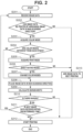
- Fig. 2 is a flowchart illustrating an example of the operation of the image forming apparatus 100 according to the present embodiment.
- Fig. 2 illustrates the flow of the processing performed by the image forming apparatus 100 from the reception of image data to the start of printing.
- step S201 the image forming apparatus 100 receives image data from the host apparatus 190 via the host IF 112.
- the host IF 112 stores the received image data in the RAM 114 and notifies the main controller 111 that image data is newly received.
- step S202 the main controller 111 determines whether the image data received and stored in the RAM 114 in step S201 can be printed by arranging the image data in the main scanning direction of a sheet. Based on the width of the image data stored in the RAM 114 and the margin width of the sheet in the main scanning direction of the sheet, the main controller 111 determines whether the image data can be printed by arranging the image data in the main scanning direction of the sheet. If the margin width of the sheet is greater than a width required to place the image data, the main controller 111 determines that the image data can be printed by arranging the image data in the main scanning direction of the sheet. If the main controller 111 determines that the image data can be printed (YES in step S202), the processing proceeds to step S203. If the main controller 111 determines that the image data cannot be printed (NO in step S202), the processing proceeds to step S213.
- step S203 the main controller 111 acquires the color mode of the image data received and stored in the RAM 114 in step S201 and registers the color mode of the image data in a color mode management table.
- the color mode management table is a table for managing the color mode of image data and is held in the RAM 114.
- the color mode management table holds information regarding an identifier (ID) for uniquely identifying image data and the color mode of the image data in association with each other.
- step S204 the main controller 111 references the color mode management table stored in the RAM 114 and determines whether the color modes of pieces of image data registered in the management table are different from each other.
- the main controller 111 compares the color mode of image data already received and registered in the management table with the color mode of the image data received in step S201 and registered in the management table and determines whether the color modes are different from each other. If the main controller 111 determines that the color modes of the pieces of image data registered in the management table are different from each other (YES in step S204), the processing proceeds to step S205. If, on the other hand, the main controller 111 determines that the color modes of the pieces of image data registered in the management table are the same as each other (NO in step S204), the processing proceeds to step S208. If only a single color mode of image data is registered in the color mode management table, the processing proceeds to step S208.
- step S205 the main controller 111 acquires the set print mode from the ROM 115.
- step S206 the main controller 111 determines whether the print mode acquired in step S205 is the sheet saving mode. If the main controller 111 determines that the print mode is the sheet saving mode (YES in step S206), the processing proceeds to step S207. If the main controller 111 determines that the print mode is not the sheet saving mode, i.e., the print mode is the setting priority mode in this example (NO in step S206), the processing proceeds to step S213.
- the main controller 111 changes the color modes of the pieces of image data so that the color modes of the pieces of image data registered in the color mode management table are a single color mode.
- the main controller 111 determines any one of the color modes of the pieces of image data registered in the management table and changes the color modes of the pieces of image data to the determined color mode. For example, according to the numbers of colors of the color modes or the numbers of gradations of the color modes, the main controller 111 determines one of the color modes of the pieces of image data registered in the management table. For example, in a case where the main controller 111 makes the determination according to the numbers of colors of the color modes, the main controller 111 determines the color mode having the most colors. In a case where the main controller 111 makes the determination according to the numbers of gradations of the color modes, the main controller 111 determines the color mode having the most gradations.
- step S208 the main controller 111 stores the image data received and stored in the RAM 114 in step S201 as an image to be placed in the main scanning direction of the sheet in the HDD 118.
- step S209 the main controller 111 calculates the margin width in the main scanning direction of the sheet after the image data stored in the HDD 118 is placed in step S208.
- the margin width in the main scanning direction of the sheet calculated in step S209 is held in the RAM 114.
- the main controller 111 acquires the margin width in the main scanning direction of the sheet by subtracting a length required to place the image data stored in the HDD 118 in step S208 from the margin width calculated in the past and held in the RAM 114.
- step S210 based on the margin width in the main scanning direction of the sheet calculated in step S209, the main controller 111 determines whether there is a further margin for placing image data in the main scanning direction of the sheet. For example, if the margin width in the main scanning direction of the sheet is greater than a predetermined threshold, the main controller 111 determines that there is a further margin for placing image data. If the main controller 111 determines that there is a margin for placing image data (YES in step S210), the processing proceeds to step S211. If the main controller 111 determines that there is no margin for placing image data (NO in step S210), the processing proceeds to step S212.
- step S211 the main controller 111 waits to receive next image data and determines whether next image data is received within a predetermined time. For example, the time to wait for the reception of image data is stored as a parameter in the ROM 115. If the main controller 111 determines that next image data is received within the predetermined time (YES in step S211), the processing returns to step S201. If, on the other hand, the main controller 111 determines that next image data is not received within the predetermined time (NO in step S211), the processing proceeds to step S212. That is, if next image data is received before the predetermined time elapses, the main controller 111 executes the process of step S201. If next image data is not received even after the predetermined time elapses, the main controller 111 executes the process of step S212.
- step S212 the main controller 111 references the color mode management table stored in the RAM 114 and starts printing the pieces of image data stored as the images to be placed in the main scanning direction of the sheet in the HDD 118.
- the image processing unit 116 performs image processing on the pieces of image data stored as the images to be placed in the main scanning direction of the sheet in the HDD 118, generates a single piece of image data by combining the pieces of image data, and stores the single piece of image data in the RAM 114.
- the main controller 111 requests the print controller 122 to print the image data generated by combining the pieces of image data, via the print engine IF 113 and the controller IF 121.
- the print controller 122 receives the image data generated by combining the pieces of image data from the controller unit 110 and store the image data in the RAM 124.
- the print controller 122 causes the image processing controller 125 to convert the image data stored in the RAM 124 into recording data so that the recording head 130 can use the image data for a recording operation. If the recording data is generated, the print controller 122 causes the conveyance control unit 129 to convey the sheet and causes the recording head 130 to execute the recording operation based on the recording data in conjunction with the conveyance of the sheet.
- step S213 the main controller 111 performs the process of setting the image data received and stored in the RAM 114 in step S201 as image data for next printing.
- the main controller 111 does not arrange and place the image data received and stored in the RAM 114 in step S201 in the main scanning direction of the sheet, and stores the image data as image data to be printed by placing the image data in the conveying direction of the sheet, in the HDD 118. If the color mode of the image data is registered in the color mode management table, the main controller 111 deletes the information regarding the color mode of the image data.
- step S213 the processing proceeds to step S212. If the processing proceeds from step S213 to step S212, the processing returns to step S201 after the process of step S212, and the processes of step S201 and the subsequent steps are executed using the image data stored in the HDD 118 in step S213 as received image data.
- the image forming apparatus 100 prints received image data by nesting printing for printing image data by arranging and placing the image data in the main scanning direction of a sheet according to the flowchart illustrated in Fig. 2 , and thereby can prevent the waste of a sheet. If the color mode of the received image data and the color mode of image data already received and stored in the HDD 118 are different from each other, then according to the print mode, the image forming apparatus 100 controls whether to start printing the stored image data. Consequently, even in a case where pieces of image data of which the color modes are different from each other are received, it is possible to perform control to appropriately change the color modes of the pieces of image data so that the color modes are the same as each other, and wait without starting printing. Thus, it is possible to prevent the waste of a sheet.
- the image forming apparatus 100 starts printing image data.
- the present embodiment is not limited to this.
- the image forming apparatus 100 may be configured to start printing the image data.
- the print mode is the sheet saving mode
- second image data of which the color mode is different from that of the first image data is received
- third image data of which the color mode is different from that of the second image data is received.
- the color modes of the received pieces of image data are changed to the color mode having the most colors among the color modes, and the pieces of image data are printed by arranging the pieces of image data in the main scanning direction of a sheet.
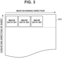
- Fig. 3 is a schematic diagram illustrating an example of the placement of pieces of image data according to the first embodiment.
- the image forming apparatus 100 receives image data (first image data) 301, image data (second image data) 302, and image data (third image data) 303 in this order from the host apparatus 190 and places the image data 301, the image data 302, and the image data 303 on a sheet 300.
- the color modes of the received image data 301 and image data 303 are the same as each other, and the color mode of the received image data 302 is different from those of the image data 301 and the image data 303.
- the color modes of the received image data 301 and image data 303 are the color
- the color mode of the received image data 302 is the monochrome.
- step S201 the image forming apparatus 100 receives the image data (first image data) 301 from the host apparatus 190 via the host IF 112.
- the host IF 112 stores the received image data 301 in the RAM 114 and notifies the main controller 111 that the image data 301 is received.
- step S202 the main controller 111 determines whether the image data 301 stored in the RAM 114 can be printed by arranging the image data 301 in the main scanning direction of the sheet 300. Since image data is not yet placed on the sheet 300, the main controller 111 determines that the image data 301 can be printed by arranging the image data 301 in the main scanning direction of the sheet 300 (YES in step S202), and the processing proceeds to step S203.
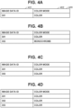
- step S203 the main controller 111 acquires the color mode of the image data 301 and registers the color mode of the image data 301 in a color mode management table 400 as illustrated in Fig. 4A .
- the color mode management table 400 holds information regarding an image data ID 401 and a color mode 402 of image data and is held in the RAM 114. Since the color mode of the image data 301 is the color, the color mode management table 400 holds "301" as the image data ID 401 and "color” as the color mode 402, as illustrated in Fig. 4A .
- step S204 the main controller 111 references the color mode management table 400 stored in the RAM 114 and determines whether the color modes of pieces of image data are different from each other.
- the main controller 111 compares the color mode of image data previously received and stored in the HDD 118 (there is no image data in this example) with the color mode of the next received (currently received) image data 301 and determines whether the color modes are different from each other.
- image data previously received and stored in the HDD 118 is also referred to simply as "previously received image data”. Since there is no previously received image data, the main controller 111 determines that the color modes of the pieces of image data are not different from each other (NO in step S204), and the processing proceeds to step S208.
- step S208 the main controller 111 stores the image data 301 as an image to be placed in the main scanning direction of the sheet 300 in the HDD 118.
- step S209 the main controller 111 calculates the margin width in the main scanning direction of the sheet 300 after the image data 301 is placed.
- the main controller 111 calculates the margin width by subtracting a length required to place the image data 301 from a width that allows the placement of image data in the main scanning direction of the sheet 300, and holds the calculated margin width in the RAM 114.
- step S210 based on the calculated margin width, the main controller 111 determines whether there is a further margin for placing image data in the main scanning direction of the sheet 300. In this example, there is a further margin for placing image data in the main scanning direction of the sheet 300.
- the main controller 111 determines that there is a further margin for placing image data (YES in step S210), and the processing proceeds to step S211.
- step S211 the main controller 111 waits to receive next image data and determines whether next image data is received within a predetermined time.
- the image forming apparatus 100 receives the next image data (second image data) 302 within the predetermined time.
- the main controller 111 determines that the next image data 302 is received within the predetermined time (YES in step S211), and the processing returns to step S201.
- step S201 the host IF 112 stores the received image data 302 in the RAM 114 and notifies the main controller 111 that the image data 302 is received.
- step S202 the main controller 111 determines whether the image data 302 stored in the RAM 114 can be printed by arranging the image data 302 in the main scanning direction of the sheet 300.
- the image data 301 is already placed on the sheet 300, and the margin width in the main scanning direction of the sheet 300 after the image data 301 is placed is greater than a width required to place the image data 302.
- the main controller 111 determines that the image data 302 can be printed by arranging the image data 302 with the image data 301 in the main scanning direction of the sheet 300 (YES in step S202), and the processing proceeds to step S203.
- step S203 the main controller 111 acquires the color mode of the image data 302 and registers the color mode of the image data 302 in the color mode management table 400 stored in the RAM 114 as illustrated in Fig. 4B . Since the color mode of the image data 302 is the monochrome, the color mode management table 400 stored in the RAM 114 enters the state where information indicating that the image data ID 401 is "302" and the color mode 402 is "monochrome" is added as illustrated in Fig. 4B .
- step S204 the main controller 111 references the color mode management table 400 stored in the RAM 114 and determines whether the color modes of pieces of image data are different from each other.
- the main controller 111 compares the color mode of the previously received image data 301 with the color mode of the next received (currently received) image data 302 and determines whether the color modes are different from each other. Since the color mode of the previously received image data 301 is the color and the color mode of the next received image data 302 is the monochrome, the main controller 111 determines that the color modes are different from each other (YES in step S204), and the processing proceeds to step S205.
- step S205 the main controller 111 acquires the print mode from the ROM 115.
- step S206 the main controller 111 determines whether the print mode is the sheet saving mode.
- the print mode is set to the sheet saving mode.
- the main controller 111 determines that the print mode is the sheet saving mode (YES in step S206), and the processing proceeds to step S207.
- step S207 the main controller 111 changes the color modes of the pieces of image data according to the color mode of the previously received image data 301 and the color mode of the next received image data 302. Since the color mode of the image data 301 is the color and the color mode of the image data 302 is the monochrome, the main controller 111 changes the color mode of the image data 302 to the color, which is the color mode having the most colors. Consequently, the color mode management table 400 stored in the RAM 114 enters the state where the information is changed to information indicating that the image data ID 401 is "302" and the color mode 402 is "color” as illustrated in Fig. 4C .
- step S208 the main controller 111 stores the image data 302 as an image to be placed in the main scanning direction of the sheet 300 in the HDD 118.
- step S209 the main controller 111 calculates the margin width in the main scanning direction of the sheet 300 after the image data 302 is placed in addition to the image data 301.
- the main controller 111 calculates the margin width by subtracting a length required to place the image data 302 from the margin width after the image data 301 is placed that is stored in the RAM 114, and holds the calculated margin width in the RAM 114.
- step S210 based on the calculated margin width, the main controller 111 determines whether there is a further margin for placing image data in the main scanning direction of the sheet 300. In this example, there is a further margin for placing image data in the main scanning direction of the sheet 300.
- the main controller 111 determines that there is a further margin for placing image data (YES in step S210), and the processing proceeds to step S211.
- step S211 the main controller 111 waits to receive next image data and determines whether next image data is received within the predetermined time.
- the image forming apparatus 100 receives the next image data (third image data) 303 within the predetermined time.
- the main controller 111 determines that the next image data 303 is received within the predetermined time (YES in step S211), and the processing returns to step S201.
- step S201 the host IF 112 stores the received image data 303 in the RAM 114 and notifies the main controller 111 that the image data 303 is received.
- step S202 the main controller 111 determines whether the image data 303 stored in the RAM 114 can be printed by arranging the image data 303 in the main scanning direction of the sheet 300.
- the image data 301 and the image data 302 are already placed on the sheet 300, and the margin width in the main scanning direction of the sheet 300 after the image data 301 and the image data 302 are placed is greater than a width required to place the image data 303.
- the main controller 111 determines that the image data 303 can be printed by arranging the image data 303 with the image data 301 and the image data 302 in the main scanning direction of the sheet 300 (YES in step S202), and the processing proceeds to step S203.
- step S203 the main controller 111 acquires the color mode of the image data 303 and registers the color mode of the image data 303 in the color mode management table 400 stored in the RAM 114 as illustrated in Fig. 4D . Since the color mode of the image data 303 is the color, the color mode management table 400 stored in the RAM 114 enters the state where information indicating that the image data ID 401 is "303" and the color mode 402 is "color” is added as illustrated in Fig. 4D .
- step S204 the main controller 111 references the color mode management table 400 stored in the RAM 114 and determines whether the color modes of pieces of image data are different from each other.
- the main controller 111 compares the color mode of the previously received image data 302 with the color mode of the next received (currently received) image data 303 and determines whether the color modes are different from each other. Since the color mode of the previously received image data 302 is the color and the color mode of the next received image data 303 is the color, the main controller 111 determines that the color modes are not different from each other (NO in step S204), and the processing proceeds to step S208.
- step S208 the main controller 111 stores the image data 303 as an image to be placed in the main scanning direction of the sheet 300 in the HDD 118.
- step S209 the main controller 111 calculates the margin width in the main scanning direction of the sheet 300 after the image data 303 is placed in addition to the image data 301 and the image data 302.
- the main controller 111 calculates the margin width by subtracting a length required to place the image data 303 from the margin width after the image data 301 and the image data 302 are placed that is stored in the RAM 114, and holds the calculated margin width in the RAM 114.
- step S210 based on the calculated margin width, the main controller 111 determines whether there is a further margin for placing image data in the main scanning direction of the sheet 300. In this example, there is a further margin for placing image data in the main scanning direction of the sheet 300.
- the main controller 111 determines that there is a further margin for placing image data (YES in step S210), and the processing proceeds to step S211.
- step S211 the main controller 111 waits to receive next image data and determines whether next image data is received within the predetermined time.
- the image forming apparatus 100 does not receive next image data within the predetermined time. That is, the predetermined time elapses in the state where next image data is not received.
- the main controller 111 determines that next image data is not received within the predetermined time (NO in step S211), and the processing proceeds to step S212.
- step S212 the main controller 111 references the color mode management table 400 illustrated in Fig. 4D that is stored in the RAM 114, and starts printing the image data 301, the image data 302, and the image data 303.
- the image processing unit 116 performs image processing on the image data 301, the image data 302, and the image data 303, generates a single piece of image data by combining the image data 301, the image data 302, and the image data 303, and stores the single piece of image data in the RAM 114.
- the main controller 111 requests the print controller 122 to print the image data generated by combining the image data 301, the image data 302, and the image data 303, via the print engine IF 113 and the controller IF 121.
- the print controller 122 stores the received image data generated by combining the image data 301, the image data 302, and the image data 303 in the RAM 124.
- the print controller 122 causes the image processing controller 125 to convert the stored image data generated by combining the image data 301, the image data 302, and the image data 303 into recording data so that the recording head 130 can use the image data for a recording operation. If the recording data is generated, the print controller 122 causes the conveyance control unit 129 to convey the sheet 300 and causes the recording head 130 to execute the recording operation based on the recording data in conjunction with the conveyance of the sheet 300.
- the color modes of the received pieces of image data are changed to the color mode having the most colors among the color modes if the print mode is the sheet saving mode, and the pieces of image data are arranged in the main scanning direction of a sheet. Further, by waiting for next image data, it is possible to prevent the waste of a sheet.
- the print mode is the setting priority mode
- second image data of which the color mode is different from that of the first image data is received.
- the print mode is the setting priority mode
- the pieces of image data of which the color modes are different from each other are not printed by arranging the pieces of image data in the main scanning direction of a sheet, and are printed in the set color modes.
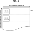
- Fig. 5 is a schematic diagram illustrating an example of the placement of pieces of image data according to the second embodiment.
- the image forming apparatus 100 receives image data (first image data) 501 and image data (second image data) 502 in this order from the host apparatus 190 and places the image data 501 and the image data 502 on a sheet 500.
- the color mode of the received image data 502 is different from that of the image data 501.
- the color mode of the received image data 501 is the color
- the color mode of the received image data 502 is the monochrome.
- step S201 the image forming apparatus 100 receives the image data (first image data) 501 from the host apparatus 190 via the host IF 112.
- the host IF 112 stores the received image data 501 in the RAM 114 and notifies the main controller 111 that the image data 501 is received.
- step S202 the main controller 111 determines whether the image data 501 stored in the RAM 114 can be printed by arranging the image data 501 in the main scanning direction of the sheet 500. Since image data is not yet placed on the sheet 500, the main controller 111 determines that the image data 501 can be printed by arranging the image data 501 in the main scanning direction of the sheet 500 (YES in step S202), and the processing proceeds to step S203.
- step S203 the main controller 111 acquires the color mode of the image data 501 and registers the color mode of the image data 501 in a color mode management table 600 as illustrated in Fig. 6A .
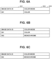
- the color mode management table 600 holds information regarding an image data ID 601 and a color mode 602 of image data and is held in the RAM 114. Since the color mode of the image data 501 is the color, the color mode management table 600 enters the state where the image data ID 601 is "501" and the color mode 602 is "color” as illustrated in Fig. 6A .
- step S204 the main controller 111 references the color mode management table 600 stored in the RAM 114 and determines whether the color modes of pieces of image data are different from each other.
- the main controller 111 compares the color mode of previously received image data (there is no image data in this example) with the color mode of the next received (currently received) image data 501 and determines whether the color modes are different from each other. Since there is no previously received image data, the main controller 111 determines that the color modes of the pieces of image data are not different from each other (NO in step S204), and the processing proceeds to step S208.
- step S208 the main controller 111 stores the image data 501 as an image to be placed in the main scanning direction of the sheet 500, in the HDD 118.
- step S209 the main controller 111 calculates the margin width in the main scanning direction of the sheet 500 after the image data 501 is placed.
- the main controller 111 calculates the margin width by subtracting a length required to place the image data 501 from a width that allows the placement of image data in the main scanning direction of the sheet 500, and holds the calculated margin width in the RAM 114.
- step S210 based on the calculated margin width, the main controller 111 determines whether there is a further margin for placing image data in the main scanning direction of the sheet 500. In this example, there is a further margin for placing image data in the main scanning direction of the sheet 500.
- the main controller 111 determines that there is a further margin for placing image data (YES in step S210), and the processing proceeds to step S211.
- step S211 the main controller 111 waits to receive next image data and determines whether next image data is received within a predetermined time.
- the image forming apparatus 100 receives the next image data (second image data) 502 within the predetermined time.
- the main controller 111 determines that the next image data 502 is received within the predetermined time (YES in step S211), and the processing returns to step S201.
- step S201 the host IF 112 stores the received image data 502 in the RAM 114 and notifies the main controller 111 that the image data 502 is received.
- step S202 the main controller 111 determines whether the image data 502 stored in the RAM 114 can be printed by arranging the image data 502 in the main scanning direction of the sheet 500.
- the image data 501 is already placed on the sheet 500, and the margin width in the main scanning direction of the sheet 500 after the image data 501 is placed is greater than a width required to place the image data 502.
- the main controller 111 determines that the image data 502 can be printed by arranging the image data 502 with the image data 501 in the main scanning direction of the sheet 500 (YES in step S202), and the processing proceeds to step S203.
- step S203 the main controller 111 acquires the color mode of the image data 502 and registers the color mode of the image data 502 in the color mode management table 600 stored in the RAM 114 as illustrated in Fig. 6B . Since the color mode of the image data 502 is the monochrome, the color mode management table 600 stored in the RAM 114 enters the state where information indicating that the image data ID 601 is "502" and the color mode 602 is "monochrome" is added as illustrated in Fig. 6B .
- step S204 the main controller 111 references the color mode management table 600 stored in the RAM 114 and determines whether the color modes of pieces of image data are different from each other.
- the main controller 111 compares the color mode of the previously received image data 501 with the color mode of the next received (currently received) image data 502 and determines whether the color modes are different from each other. Since the color mode of the previously received image data 501 is the color and the color mode of the next received image data 502 is the monochrome, the main controller 111 determines that the color modes are different from each other (YES in step S204), and the processing proceeds to step S205.
- step S205 the main controller 111 acquires the print mode from the ROM 115.
- step S206 the main controller 111 determines whether the print mode is the sheet saving mode.
- the print mode is set to the setting priority mode.
- the main controller 111 determines that the print mode is not the sheet saving mode (NO in step S206), and the processing proceeds to step S213.
- step S213 the main controller 111 does not print the image data 502 by arranging the image data 502 with the image data 501 in the main scanning direction of the sheet 500, and stores the image data 502 as image data to be printed by placing the image data 502 in the conveying direction of the sheet 500, in the HDD 118. In this manner, the main controller 111 stores the image data 502 as image data for next printing to be performed after the image data 501 is printed, in the HDD 118. The main controller 111 also deletes the information (the image data ID 601 and the color mode 602) regarding the image data 502 from the color mode management table 600 stored in the RAM 114. Thus, the color mode management table 600 stored in the RAM 114 enters the state illustrated in Fig. 6A . After the process of step S213 is completed, the processing proceeds to step S212.
- step S212 the main controller 111 references the color mode management table 600 illustrated in Fig. 6A that is stored in the RAM 114, and starts printing the image data 501.
- the image processing unit 116 performs image processing on the image data 501 and stores the image data 501 in the RAM 114.
- the main controller 111 requests the print controller 122 to print the image data 501 via the print engine IF 113 and the controller IF 121.
- the print controller 122 stores the received image data 501 in the RAM 124.
- the print controller 122 causes the image processing controller 125 to convert the stored image data 501 into recording data so that the recording head 130 can use the image data 501 for a recording operation. If the recording data is generated, the print controller 122 causes the conveyance control unit 129 to convey the sheet 500 and causes the recording head 130 to execute the recording operation based on the recording data in conjunction with the conveyance of the sheet 500.
- step S213 Since the image data 502 is stored as image data not to be printed by arranging the image data 502 with the image data 501 in the main scanning direction of the sheet 500 but to be printed by placing the image data 502 in the conveying direction of the sheet 500, in the HDD 118 in step S213, the processing is executed from step S201 after that.
- step S201 the main controller 111 is notified that the image data 502 is received in the HDD 118.
- step S202 the main controller 111 determines whether the image data 502 stored in the HDD 118 can be printed by arranging the image data 502 in the main scanning direction of the sheet 500. Since the image data 501 is already printed and image data is not yet placed on the sheet 500, the main controller 111 determines that the image data 502 can be printed by arranging the image data 502 in the main scanning direction of the sheet 500 (YES in step S202), and the processing proceeds to step S203.
- step S203 the main controller 111 acquires the color mode of the image data 502 and registers the color mode of the image data 502 in the color mode management table 600 stored in the RAM 114 as illustrated in Fig. 6C . Since the color mode of the image data 502 is the monochrome, the color mode management table 600 stored in the RAM 114 enters the state where the image data ID 601 is "502" and the color mode 602 is "monochrome" as illustrated in Fig. 6C .
- step S204 the main controller 111 references the color mode management table 600 stored in the RAM 114 and determines whether the color modes of pieces of image data are different from each other.
- the main controller 111 compares the color mode of previously received image data with the color mode of the next received image data 502 and determines whether the color modes are different from each other. Since the image data 501 is already printed and there is no previously received image data, the main controller 111 determines that the color modes of the pieces of image data are not different from each other (NO in step S204), and the processing proceeds to step S208.
- step S208 the main controller 111 stores the image data 502 as an image to be placed in the main scanning direction of the sheet 500 in the HDD 118.
- step S209 the main controller 111 calculates the margin width in the main scanning direction of the sheet 500 after the image data 502 is placed.
- the main controller 111 calculates the margin width by subtracting a length required to place the image data 502 from a width that allows the placement of image data in the main scanning direction of the sheet 500, and holds the calculated margin width in the RAM 114.
- step S210 based on the calculated margin width, the main controller 111 determines whether there is a further margin for placing image data in the main scanning direction of the sheet 500. In this example, there is a further margin for placing image data in the main scanning direction of the sheet 500.
- the main controller 111 determines that there is a further margin for placing image data (YES in step S210), and the processing proceeds to step S211.
- step S211 the main controller 111 waits to receive next image data and determines whether next image data is received within the predetermined time.
- the image forming apparatus 100 does not receive next image data within the predetermined time. That is, the predetermined time elapses in the state where next image data is not received.
- the main controller 111 determines that next image data is not received within the predetermined time (NO in step S211), and the processing proceeds to step S212.
- step S212 the main controller 111 references the color mode management table 600 illustrated in Fig. 6C that is stored in the RAM 114, and starts printing the image data 502.
- the image processing unit 116 performs image processing on the image data 502 and stores the image data 502 in the RAM 114.
- the main controller 111 requests the print controller 122 to print the image data 502 via the print engine IF 113 and the controller IF 121.
- the print controller 122 stores the received image data 502 in the RAM 124.
- the print controller 122 causes the image processing controller 125 to convert the stored image data 502 into recording data so that the recording head 130 can use the image data 502 for a recording operation. If the recording data is generated, the print controller 122 causes the conveyance control unit 129 to convey the sheet 500 and causes the recording head 130 to execute the recording operation based on the recording data in conjunction with the conveyance of the sheet 500.
- the pieces of image data are printed in the set color modes, whereby it is possible to perform printing as intended by the user.
- the third embodiment is basically similar to the first embodiment. The differences from the first embodiment are described below, and portions similar to those in the first embodiment are not described.
- the third embodiment an example is described where, in a case where pieces of image data of which the color modes are different from each other are received and the print mode is the sheet saving mode, the color modes of the received pieces of image data are changed to the color mode having the most gradations among the color modes, and the pieces of image data are printed by arranging the pieces of image data in the main scanning direction of a sheet.
- image data (first image data) 301, image data (second image data) 302, and image data (third image data) 303 received in this order are placed on a sheet 300 as in the example of the placement illustrated in Fig. 3 .
- the color modes of the received image data 301 and image data 303 are the same as each other, and the color mode of the received image data 302 is different from those of the image data 301 and the image data 303.
- the color modes of the received image data 301 and image data 303 are the grayscale (256 gradations), and the color mode of the received image data 302 is the monochrome (two gradations).
- the flow of the processing performed by the image forming apparatus 100 is basically similar to that according to the first embodiment.
- Figs. 7A to 7D are diagrams illustrating examples of a color mode management table 700 according to the third embodiment.
- the color mode management table 700 holds information regarding an image data ID 701 and a color mode 702 of image data and is held in the RAM 114.
- the color mode management table 700 enters the state where the image data ID 701 is "301" and the color mode 702 is "grayscale (256 gradations)" as illustrated in Fig. 7A .
- the color mode management table 700 enters the state illustrated in Fig. 7B . That is, the color mode management table 700 enters the state where information indicating that the image data ID 701 is "302" and the color mode 702 is "monochrome (two gradations)" is added.
- the main controller 111 changes the color modes of the pieces of image data and continues to wait for printing.
- the main controller 111 changes the color mode of the image data 302 to the grayscale (256 gradations), which is the color mode having the most gradations, and continues to wait for printing. Consequently, the color mode management table 700 enters the state where the information is changed to information indicating that the image data ID 701 is "302" and the color mode 702 is "grayscale (256 gradations)" as illustrated in Fig. 7C .
- the color mode management table 700 enters the state illustrated in Fig. 7D . That is, the color mode management table 700 enters the state where information indicating that the image data ID 701 is "303" and the color mode 702 is "grayscale (256 gradations)" is added.
- the image forming apparatus 100 unifies the color modes of the image data 301, the image data 302, and the image data 303 into "grayscale (256 gradations)" and prints the image data 301, the image data 302, and the image data 303 by arranging the image data 301, the image data 302, and the image data 303 in the main scanning direction on the sheet 300.
- the color modes of the received pieces of image data are changed to the color mode having the most gradations among the color modes if the print mode is the sheet saving mode, and the pieces of image data are arranged in the main scanning direction of a sheet. Further, by waiting for next image data, it is possible to prevent the waste of a sheet.
- the fourth embodiment is basically similar to the first embodiment. The differences from the first embodiment are described below, and portions similar to those in the first embodiment are not described.
- the fourth embodiment an example is described where, in a case where pieces of image data of which the color modes are different from each other are received and the print mode is the sheet saving mode, the color modes of the received pieces of image data are changed to the color mode having the most colors and the most gradations among the received pieces of image data, and the pieces of image data are printed by arranging the pieces of image data in the main scanning direction of a sheet.
- image data (first image data) 301, image data (second image data) 302, and image data (third image data) 303 received in this order are placed on a sheet 300 as in the example of the placement illustrated in Fig. 3 .
- the color modes of the received image data 301, image data 302, and image data 303 are different from each other.
- the color mode of the received image data 301 is the monochrome (a single color, two gradations)
- the color mode of the received image data 302 is the grayscale (a single color, 256 gradations)
- the color mode of the received image data 303 is the color (three colors, 256 gradations).
- the color mode having the most colors and the most gradations is determined among the received pieces of image data, if the number of colors is n and the number of gradations is x, the color mode having the greatest value of x to the n-th power is determined as the color mode having the most colors and the most gradations.
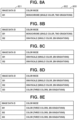
- Figs. 8A to 8E are diagrams illustrating examples of a color mode management table 800 according to the fourth embodiment.
- the color mode management table 800 holds information regarding an image data ID 801 and a color mode 802 of image data and is held in the RAM 114.
- the color mode management table 800 enters the state illustrated in Fig. 8A . That is, the color mode management table 800 enters the state where the image data ID 801 is "301" and the color mode 802 is "monochrome (single color, two gradations)".
- the color mode management table 800 enters the state illustrated in Fig. 8B . That is, the color mode management table 800 enters the state where information indicating that the image data ID 801 is "302" and the color mode 802 is "grayscale (single color, 256 gradations)" is added.
- the main controller 111 changes the color modes of the pieces of image data and continues to wait for printing.
- the main controller 111 changes the color mode of the image data 301 to the grayscale (a single color, 256 gradations), which is the color mode having the most colors and the most gradations, and continues to wait for printing. Consequently, the color mode management table 800 enters the state where the information is changed to information indicating that the image data ID 801 is "301" and the color mode 802 is "grayscale (single color, 256 gradations)" as illustrated in Fig. 8C .
- the color mode management table 800 enters the state illustrated in Fig. 8D . That is, the color mode management table 800 enters the state where information indicating that the image data ID 801 is "303" and the color mode 802 is "color (three colors, 256 gradations)" is added.
- the main controller 111 changes the color modes of the pieces of image data and continues to wait for printing.
- the main controller 111 changes the color modes of the image data 301 and the image data 302 to the color (three colors, 256 gradations), which is the color mode having the most colors and the most gradations, and continues to wait for printing. Consequently, the color mode management table 800 enters the state where the image data ID 801 is "301", "302", and "303" and the color mode 802 is "color (three colors, 256 gradations)" as illustrated in Fig. 8E .
- the image forming apparatus 100 unifies the color modes of the image data 301, the image data 302, and the image data 303 into "color (three colors, 256 gradations)" and prints the image data 301, the image data 302, and the image data 303 by arranging the image data 301, the image data 302, and the image data 303 in the main scanning direction on the sheet 300.
- the color modes of the received pieces of image data are changed to the color mode having the most colors and the most gradations among the color modes if the print mode is the sheet saving mode, and the pieces of image data are arranged in the main scanning direction of a sheet. Further, by waiting for next image data, it is possible to prevent the waste of a sheet.
- Embodiment(s) of the present invention can also be realized by a computer of a system or apparatus that reads out and executes computer executable instructions (e.g., one or more programs) recorded on a storage medium (which may also be referred to more fully as a 'non-transitory computer-readable storage medium') to perform the functions of one or more of the above-described embodiment(s) and/or that includes one or more circuits (e.g., application specific integrated circuit (ASIC)) for performing the functions of one or more of the above-described embodiment(s), and by a method performed by the computer of the system or apparatus by, for example, reading out and executing the computer executable instructions from the storage medium to perform the functions of one or more of the above-described embodiment(s) and/or controlling the one or more circuits to perform the functions of one or more of the above-described embodiment(s).
- computer executable instructions e.g., one or more programs
- a storage medium which may also be referred to more fully as
- the computer may comprise one or more processors (e.g., central processing unit (CPU), micro processing unit (MPU)) and may include a network of separate computers or separate processors to read out and execute the computer executable instructions.
- the computer executable instructions may be provided to the computer, for example, from a network or the storage medium.
- the storage medium may include, for example, one or more of a hard disk, a random-access memory (RAM), a read only memory (ROM), a storage of distributed computing systems, an optical disk (such as a compact disc (CD), digital versatile disc (DVD), or Blu-ray Disc (BD) TM ), a flash memory device, a memory card, and the like.
Landscapes
- Engineering & Computer Science (AREA)
- Theoretical Computer Science (AREA)
- Physics & Mathematics (AREA)
- General Physics & Mathematics (AREA)
- Human Computer Interaction (AREA)
- General Engineering & Computer Science (AREA)
- Signal Processing (AREA)
- Multimedia (AREA)
- Microelectronics & Electronic Packaging (AREA)
- Record Information Processing For Printing (AREA)
- Accessory Devices And Overall Control Thereof (AREA)
- Color, Gradation (AREA)
- Facsimiles In General (AREA)
Applications Claiming Priority (1)
| Application Number | Priority Date | Filing Date | Title |
|---|---|---|---|
| JP2022116389A JP2024013936A (ja) | 2022-07-21 | 2022-07-21 | 画像形成装置、画像形成装置の制御方法、及びプログラム |
Publications (2)
| Publication Number | Publication Date |
|---|---|
| EP4311216A1 true EP4311216A1 (de) | 2024-01-24 |
| EP4311216B1 EP4311216B1 (de) | 2025-10-22 |
Family
ID=87377932
Family Applications (1)
| Application Number | Title | Priority Date | Filing Date |
|---|---|---|---|
| EP23185887.9A Active EP4311216B1 (de) | 2022-07-21 | 2023-07-17 | Bilderzeugungsvorrichtung, steuerungsverfahren zur steuerung der bilderzeugungsvorrichtung und speichermedium |
Country Status (4)
| Country | Link |
|---|---|
| US (2) | US12073131B2 (de) |
| EP (1) | EP4311216B1 (de) |
| JP (1) | JP2024013936A (de) |
| CN (1) | CN117434805A (de) |
Families Citing this family (1)
| Publication number | Priority date | Publication date | Assignee | Title |
|---|---|---|---|---|
| JP7707729B2 (ja) * | 2021-08-03 | 2025-07-15 | 富士フイルムビジネスイノベーション株式会社 | 画像処理装置及び画像処理プログラム |
Citations (4)
| Publication number | Priority date | Publication date | Assignee | Title |
|---|---|---|---|---|
| US20090303514A1 (en) * | 2008-06-05 | 2009-12-10 | Sergio Puigardeu | Automatic arrangement of nested images as a function of assigned print modes |
| JP2010284821A (ja) | 2009-06-09 | 2010-12-24 | Canon Inc | 印刷装置 |
| US20150215479A1 (en) * | 2012-04-30 | 2015-07-30 | Hewlett-Packard Indigo B.V. | Work flow and finishing for print production of photograph images |
| US20160210088A1 (en) * | 2013-08-30 | 2016-07-21 | Agfa Graphics Nv | Nesting method and apparatus |
Family Cites Families (3)
| Publication number | Priority date | Publication date | Assignee | Title |
|---|---|---|---|---|
| US5719686A (en) * | 1993-12-20 | 1998-02-17 | Canon Kabushiki Kaisha | Image communicating apparatus |
| US7218414B2 (en) * | 2002-03-22 | 2007-05-15 | Canon Kabushiki Kaisha | Apparatus and method for recording document described in markup language |
| KR101569073B1 (ko) * | 2009-01-15 | 2015-11-30 | 삼성전자주식회사 | 화상형성장치 및 그의 화질 보정 방법 |
-
2022
- 2022-07-21 JP JP2022116389A patent/JP2024013936A/ja active Pending
-
2023
- 2023-07-17 EP EP23185887.9A patent/EP4311216B1/de active Active
- 2023-07-18 US US18/354,186 patent/US12073131B2/en active Active
- 2023-07-18 CN CN202310882574.5A patent/CN117434805A/zh active Pending
-
2024
- 2024-07-24 US US18/782,698 patent/US20240377999A1/en active Pending
Patent Citations (4)
| Publication number | Priority date | Publication date | Assignee | Title |
|---|---|---|---|---|
| US20090303514A1 (en) * | 2008-06-05 | 2009-12-10 | Sergio Puigardeu | Automatic arrangement of nested images as a function of assigned print modes |
| JP2010284821A (ja) | 2009-06-09 | 2010-12-24 | Canon Inc | 印刷装置 |
| US20150215479A1 (en) * | 2012-04-30 | 2015-07-30 | Hewlett-Packard Indigo B.V. | Work flow and finishing for print production of photograph images |
| US20160210088A1 (en) * | 2013-08-30 | 2016-07-21 | Agfa Graphics Nv | Nesting method and apparatus |
Also Published As
| Publication number | Publication date |
|---|---|
| US20240377999A1 (en) | 2024-11-14 |
| JP2024013936A (ja) | 2024-02-01 |
| US12073131B2 (en) | 2024-08-27 |
| CN117434805A (zh) | 2024-01-23 |
| EP4311216B1 (de) | 2025-10-22 |
| US20240028275A1 (en) | 2024-01-25 |
Similar Documents
| Publication | Publication Date | Title |
|---|---|---|
| US20240377999A1 (en) | Image forming apparatus, control method for controlling image forming apparatus, and storage medium | |
| US20160086068A1 (en) | Print control apparatus, print control method, and program | |
| US9098779B2 (en) | Recording control device, control method, and program | |
| JP2019098580A (ja) | 画像形成装置 | |
| US8810854B2 (en) | Image forming apparatus, image drawing processing method, software program, and storage medium | |
| US12511086B2 (en) | Image processing apparatus, image formation apparatus, image processing method, and storage medium | |
| US20240338156A1 (en) | Image forming apparatus, image forming method, and storage medium | |
| US12265743B2 (en) | Print job processing apparatus, print job processing method, image forming apparatus, and computer readable storage medium | |
| US12379883B2 (en) | Image forming apparatus, method for controlling image forming apparatus, and storage medium for controlling start of printing | |
| JP7006372B2 (ja) | 画像処理システム、画像処理装置、画像処理方法、及びプログラム | |
| US20250208807A1 (en) | Image forming apparatus, print control method, and computer readable medium | |
| US20260006143A1 (en) | Printing apparatus, control method, and storage medium | |
| US20240177266A1 (en) | Image processing apparatus, image forming apparatus, image processing method, and storage medium | |
| JP2013123878A (ja) | バリアブル印刷データ処理時間予測プログラムおよび画像形成装置。 | |
| EP4516512A1 (de) | Druckvorrichtung, steuerungsverfahren, nichttransitorisches computerlesbares speichermedium und computerprogramm | |
| US11899997B1 (en) | Image arrangement apparatus and image forming apparatus, image arrangement method, and computer readable storage medium | |
| JP2025040837A (ja) | 画像処理装置、画像処理装置の制御方法及びプログラム | |
| US20260111156A1 (en) | Image forming apparatus, information processing apparatus, method of managing image forming apparatus, image forming system, and storage medium | |
| JP7584929B2 (ja) | 印刷装置、制御方法及びプログラム | |
| JP2004261994A (ja) | 印刷制御装置、印刷制御方法および印刷制御プログラム | |
| JP2025001941A (ja) | 画像形成装置、画像形成方法、及びプログラム | |
| JP2007108861A (ja) | プリンタ装置 | |
| JP2013120195A (ja) | 画像形成装置 | |
| KR20060029742A (ko) | 프린터 카드 및 이를 구비한 인쇄 시스템 | |
| JP2001105667A (ja) | プリンタ |
Legal Events
| Date | Code | Title | Description |
|---|---|---|---|
| PUAI | Public reference made under article 153(3) epc to a published international application that has entered the european phase |
Free format text: ORIGINAL CODE: 0009012 |
|
| STAA | Information on the status of an ep patent application or granted ep patent |
Free format text: STATUS: THE APPLICATION HAS BEEN PUBLISHED |
|
| AK | Designated contracting states |
Kind code of ref document: A1 Designated state(s): AL AT BE BG CH CY CZ DE DK EE ES FI FR GB GR HR HU IE IS IT LI LT LU LV MC ME MK MT NL NO PL PT RO RS SE SI SK SM TR |
|
| STAA | Information on the status of an ep patent application or granted ep patent |
Free format text: STATUS: REQUEST FOR EXAMINATION WAS MADE |
|
| 17P | Request for examination filed |
Effective date: 20240724 |
|
| RBV | Designated contracting states (corrected) |
Designated state(s): AL AT BE BG CH CY CZ DE DK EE ES FI FR GB GR HR HU IE IS IT LI LT LU LV MC ME MK MT NL NO PL PT RO RS SE SI SK SM TR |
|
| STAA | Information on the status of an ep patent application or granted ep patent |
Free format text: STATUS: EXAMINATION IS IN PROGRESS |
|
| 17Q | First examination report despatched |
Effective date: 20241206 |
|
| GRAP | Despatch of communication of intention to grant a patent |
Free format text: ORIGINAL CODE: EPIDOSNIGR1 |
|
| STAA | Information on the status of an ep patent application or granted ep patent |
Free format text: STATUS: GRANT OF PATENT IS INTENDED |
|
| RIC1 | Information provided on ipc code assigned before grant |
Ipc: H04N 1/387 20060101ALI20250430BHEP Ipc: H04N 1/60 20060101ALI20250430BHEP Ipc: H04N 1/46 20060101ALI20250430BHEP Ipc: G06F 3/12 20060101ALI20250430BHEP Ipc: H04N 1/23 20060101AFI20250430BHEP |
|
| INTG | Intention to grant announced |
Effective date: 20250523 |
|
| GRAS | Grant fee paid |
Free format text: ORIGINAL CODE: EPIDOSNIGR3 |
|
| GRAA | (expected) grant |
Free format text: ORIGINAL CODE: 0009210 |
|
| STAA | Information on the status of an ep patent application or granted ep patent |
Free format text: STATUS: THE PATENT HAS BEEN GRANTED |
|
| AK | Designated contracting states |
Kind code of ref document: B1 Designated state(s): AL AT BE BG CH CY CZ DE DK EE ES FI FR GB GR HR HU IE IS IT LI LT LU LV MC ME MK MT NL NO PL PT RO RS SE SI SK SM TR |
|
| REG | Reference to a national code |
Ref country code: CH Ref legal event code: F10 Free format text: ST27 STATUS EVENT CODE: U-0-0-F10-F00 (AS PROVIDED BY THE NATIONAL OFFICE) Effective date: 20251022 Ref country code: GB Ref legal event code: FG4D |
|
| REG | Reference to a national code |
Ref country code: DE Ref legal event code: R096 Ref document number: 602023007707 Country of ref document: DE |
|
| REG | Reference to a national code |
Ref country code: IE Ref legal event code: FG4D |
|
| REG | Reference to a national code |
Ref country code: NL Ref legal event code: MP Effective date: 20251022 |
|
| PG25 | Lapsed in a contracting state [announced via postgrant information from national office to epo] |
Ref country code: NL Free format text: LAPSE BECAUSE OF FAILURE TO SUBMIT A TRANSLATION OF THE DESCRIPTION OR TO PAY THE FEE WITHIN THE PRESCRIBED TIME-LIMIT Effective date: 20251022 |
|
| PG25 | Lapsed in a contracting state [announced via postgrant information from national office to epo] |
Ref country code: ES Free format text: LAPSE BECAUSE OF FAILURE TO SUBMIT A TRANSLATION OF THE DESCRIPTION OR TO PAY THE FEE WITHIN THE PRESCRIBED TIME-LIMIT Effective date: 20251022 |
|
| REG | Reference to a national code |
Ref country code: LT Ref legal event code: MG9D |
|
| PG25 | Lapsed in a contracting state [announced via postgrant information from national office to epo] |
Ref country code: NO Free format text: LAPSE BECAUSE OF FAILURE TO SUBMIT A TRANSLATION OF THE DESCRIPTION OR TO PAY THE FEE WITHIN THE PRESCRIBED TIME-LIMIT Effective date: 20260122 |
|
| PG25 | Lapsed in a contracting state [announced via postgrant information from national office to epo] |
Ref country code: HR Free format text: LAPSE BECAUSE OF FAILURE TO SUBMIT A TRANSLATION OF THE DESCRIPTION OR TO PAY THE FEE WITHIN THE PRESCRIBED TIME-LIMIT Effective date: 20251022 Ref country code: AT Free format text: LAPSE BECAUSE OF FAILURE TO SUBMIT A TRANSLATION OF THE DESCRIPTION OR TO PAY THE FEE WITHIN THE PRESCRIBED TIME-LIMIT Effective date: 20251022 Ref country code: FI Free format text: LAPSE BECAUSE OF FAILURE TO SUBMIT A TRANSLATION OF THE DESCRIPTION OR TO PAY THE FEE WITHIN THE PRESCRIBED TIME-LIMIT Effective date: 20251022 |
|
| REG | Reference to a national code |
Ref country code: AT Ref legal event code: MK05 Ref document number: 1850287 Country of ref document: AT Kind code of ref document: T Effective date: 20251022 |
|
| PG25 | Lapsed in a contracting state [announced via postgrant information from national office to epo] |
Ref country code: RS Free format text: LAPSE BECAUSE OF FAILURE TO SUBMIT A TRANSLATION OF THE DESCRIPTION OR TO PAY THE FEE WITHIN THE PRESCRIBED TIME-LIMIT Effective date: 20260122 |
|
| PG25 | Lapsed in a contracting state [announced via postgrant information from national office to epo] |
Ref country code: IS Free format text: LAPSE BECAUSE OF FAILURE TO SUBMIT A TRANSLATION OF THE DESCRIPTION OR TO PAY THE FEE WITHIN THE PRESCRIBED TIME-LIMIT Effective date: 20260222 |
|
| PG25 | Lapsed in a contracting state [announced via postgrant information from national office to epo] |
Ref country code: PT Free format text: LAPSE BECAUSE OF FAILURE TO SUBMIT A TRANSLATION OF THE DESCRIPTION OR TO PAY THE FEE WITHIN THE PRESCRIBED TIME-LIMIT Effective date: 20260223 |
|
| PG25 | Lapsed in a contracting state [announced via postgrant information from national office to epo] |
Ref country code: PL Free format text: LAPSE BECAUSE OF FAILURE TO SUBMIT A TRANSLATION OF THE DESCRIPTION OR TO PAY THE FEE WITHIN THE PRESCRIBED TIME-LIMIT Effective date: 20251022 |
|
| PG25 | Lapsed in a contracting state [announced via postgrant information from national office to epo] |
Ref country code: LV Free format text: LAPSE BECAUSE OF FAILURE TO SUBMIT A TRANSLATION OF THE DESCRIPTION OR TO PAY THE FEE WITHIN THE PRESCRIBED TIME-LIMIT Effective date: 20251022 |