EP4311383A2 - Alimentation électrique comprenant une protection d'entrée - Google Patents
Alimentation électrique comprenant une protection d'entrée Download PDFInfo
- Publication number
- EP4311383A2 EP4311383A2 EP23181316.3A EP23181316A EP4311383A2 EP 4311383 A2 EP4311383 A2 EP 4311383A2 EP 23181316 A EP23181316 A EP 23181316A EP 4311383 A2 EP4311383 A2 EP 4311383A2
- Authority
- EP
- European Patent Office
- Prior art keywords
- subsystem
- housing
- power supply
- ingress
- portable power
- Prior art date
- Legal status (The legal status is an assumption and is not a legal conclusion. Google has not performed a legal analysis and makes no representation as to the accuracy of the status listed.)
- Pending
Links
Images


Classifications
-
- H—ELECTRICITY
- H01—ELECTRIC ELEMENTS
- H01M—PROCESSES OR MEANS, e.g. BATTERIES, FOR THE DIRECT CONVERSION OF CHEMICAL ENERGY INTO ELECTRICAL ENERGY
- H01M50/00—Constructional details or processes of manufacture of the non-active parts of electrochemical cells other than fuel cells, e.g. hybrid cells
- H01M50/20—Mountings; Secondary casings or frames; Racks, modules or packs; Suspension devices; Shock absorbers; Transport or carrying devices; Holders
- H01M50/233—Mountings; Secondary casings or frames; Racks, modules or packs; Suspension devices; Shock absorbers; Transport or carrying devices; Holders characterised by physical properties of casings or racks, e.g. dimensions
- H01M50/24—Mountings; Secondary casings or frames; Racks, modules or packs; Suspension devices; Shock absorbers; Transport or carrying devices; Holders characterised by physical properties of casings or racks, e.g. dimensions adapted for protecting batteries from their environment, e.g. from corrosion
-
- H—ELECTRICITY
- H05—ELECTRIC TECHNIQUES NOT OTHERWISE PROVIDED FOR
- H05K—PRINTED CIRCUITS; CASINGS OR CONSTRUCTIONAL DETAILS OF ELECTRIC APPARATUS; MANUFACTURE OF ASSEMBLAGES OF ELECTRICAL COMPONENTS
- H05K7/00—Constructional details common to different types of electric apparatus
- H05K7/14—Mounting supporting structure in casing or on frame or rack
- H05K7/1422—Printed circuit boards receptacles, e.g. stacked structures, electronic circuit modules or box like frames
- H05K7/1427—Housings
- H05K7/1432—Housings specially adapted for power drive units or power converters
- H05K7/14327—Housings specially adapted for power drive units or power converters having supplementary functional units, e.g. data transfer modules or displays or user interfaces
-
- H—ELECTRICITY
- H01—ELECTRIC ELEMENTS
- H01M—PROCESSES OR MEANS, e.g. BATTERIES, FOR THE DIRECT CONVERSION OF CHEMICAL ENERGY INTO ELECTRICAL ENERGY
- H01M50/00—Constructional details or processes of manufacture of the non-active parts of electrochemical cells other than fuel cells, e.g. hybrid cells
- H01M50/20—Mountings; Secondary casings or frames; Racks, modules or packs; Suspension devices; Shock absorbers; Transport or carrying devices; Holders
- H01M50/298—Mountings; Secondary casings or frames; Racks, modules or packs; Suspension devices; Shock absorbers; Transport or carrying devices; Holders characterised by the wiring of battery packs
-
- H—ELECTRICITY
- H01—ELECTRIC ELEMENTS
- H01M—PROCESSES OR MEANS, e.g. BATTERIES, FOR THE DIRECT CONVERSION OF CHEMICAL ENERGY INTO ELECTRICAL ENERGY
- H01M50/00—Constructional details or processes of manufacture of the non-active parts of electrochemical cells other than fuel cells, e.g. hybrid cells
- H01M50/60—Arrangements or processes for filling or topping-up with liquids; Arrangements or processes for draining liquids from casings
- H01M50/691—Arrangements or processes for draining liquids from casings; Cleaning battery or cell casings
-
- H—ELECTRICITY
- H02—GENERATION; CONVERSION OR DISTRIBUTION OF ELECTRIC POWER
- H02J—ELECTRIC POWER NETWORKS; CIRCUIT ARRANGEMENTS OR SYSTEMS FOR SUPPLYING OR DISTRIBUTING ELECTRIC POWER; SYSTEMS FOR STORING ELECTRIC ENERGY
- H02J7/00—Circuit arrangements for charging or discharging batteries or for supplying loads from batteries
- H02J7/70—Circuit arrangements for charging or discharging batteries or for supplying loads from batteries characterised by the mechanical construction
-
- H—ELECTRICITY
- H02—GENERATION; CONVERSION OR DISTRIBUTION OF ELECTRIC POWER
- H02J—ELECTRIC POWER NETWORKS; CIRCUIT ARRANGEMENTS OR SYSTEMS FOR SUPPLYING OR DISTRIBUTING ELECTRIC POWER; SYSTEMS FOR STORING ELECTRIC ENERGY
- H02J7/00—Circuit arrangements for charging or discharging batteries or for supplying loads from batteries
- H02J7/855—Circuit arrangements for charging or discharging batteries or for supplying loads from batteries with circuits adapted for supplying loads from the battery
-
- H—ELECTRICITY
- H05—ELECTRIC TECHNIQUES NOT OTHERWISE PROVIDED FOR
- H05K—PRINTED CIRCUITS; CASINGS OR CONSTRUCTIONAL DETAILS OF ELECTRIC APPARATUS; MANUFACTURE OF ASSEMBLAGES OF ELECTRICAL COMPONENTS
- H05K5/00—Casings, cabinets or drawers for electric apparatus
- H05K5/06—Hermetically-sealed casings
- H05K5/061—Hermetically-sealed casings sealed by a gasket held between a removable cover and a body, e.g. O-ring, packing
-
- H—ELECTRICITY
- H05—ELECTRIC TECHNIQUES NOT OTHERWISE PROVIDED FOR
- H05K—PRINTED CIRCUITS; CASINGS OR CONSTRUCTIONAL DETAILS OF ELECTRIC APPARATUS; MANUFACTURE OF ASSEMBLAGES OF ELECTRICAL COMPONENTS
- H05K5/00—Casings, cabinets or drawers for electric apparatus
- H05K5/06—Hermetically-sealed casings
- H05K5/069—Other details of the casing, e.g. wall structure, passage for a connector, a cable, a shaft
Definitions
- the present disclosure relates to portable power supplies, and more specifically to ingress protection for portable power supplies.
- Portable power supplies are used to supply power to a variety of tools.
- the portability of the power supply allows for transportation of the power supply such that the power supply can power tools and devices in different locations.
- a portable power supply including a housing, a power source, a first subsystem electrically connected to the power source and positioned within the housing, and a second subsystem electrically connected to the power source and positioned within the housing.
- the plurality of wires electrically connect the power source, the first subsystem, and the second subsystem.
- the plurality of wires are ingress protected.
- the first subsystem and the second subsystem are ingress protected when positioned in the housing.
- a portable power supply including a housing movable between a static use mode and a transportation mode.
- a first subsystem is ingress protected and positioned within the housing.
- a weep hole is positioned at a lower wall of the housing. The lower wall is parallel with a ground surface in the static use mode, and the lower wall is angled relative to the ground surface in the transportation mode. The weep hole weeps in the static use mode and the transportation mode.
- a portable power supply including a housing, a first subsystem being ingress protected and positioned within the housing, a second subsystem being ingress protected and positioned within the housing, and a human-machine interface that is detached from the housing.
- the first subsystem includes a first ingress protection rating
- the second subsystem includes a second ingress protection rating.
- the first ingress protection rating is different than the second ingress protection rating.
- a portable power supply comprising:
- the portable power supply may include an ingress protection rating, and wherein the ingress protection rating of the portable power supply may remain constant when the first subsystem or the second subsystem is removed from the housing.
- the first subsystem may be ingress protected when removed from the housing.
- the first subsystem may be only ingress protected when positioned within the housing.
- the first subsystem may include a lid and a body, the lid and the body being joined with a gasket, and wherein a grommet may be positioned proximate the gasket to allow wires to pass from within the body to a location external from the body.
- the first subsystem may include a gore valve positioned on the body, the gore valve configured to equalize an internal pressure within the body.
- the second subsystem may include louvered vents configured to divert water ingress away from the second subsystem.
- the housing may be selectively perforated.
- the first subsystem and the second subsystem may be sealed against the housing.
- a portable power supply comprising:
- the portable power supply may further comprise a second subsystem positioned within the housing and being ingress protected when positioned within the housing.
- the first subsystem may include a first ingress protection rating and the second subsystem may include a second ingress protection rating, and wherein the first ingress protection rating may be different than the second ingress protection rating.
- a path may be formed between the first subsystem and the second system, the path configured to route debris and/or water to the weep hole.
- debris and standing water may be prevented from entering the housing through the weep hole.
- a portable power supply comprising:
- the portable power supply may include a third ingress protection rating, the third ingress protection rating remaining constant when the first subsystem or the second subsystem is removed from the housing.
- the third ingress protection rating may be different than the first ingress protection rating or the second ingress protection rating.
- the human-machine interface may communicate with the portable power supply through a Bluetooth connection.
- the human-machine interface may include an application software program executable on a smart device.
- the first subsystem may be a power source, the human-machine interface configured to communicate with the power source through a wired connection.
- the terms “first”, “second”, and “third” may be used interchangeably to distinguish one component from another and are not intended to signify location or importance of the individual components.
- the singular forms “a,” “an,” and “the” include plural references unless the context clearly dictates otherwise.
- the terms “coupled,” “fixed,” “attached to,” and the like refer to both direct coupling, fixing, or attaching, as well as indirect coupling, fixing, or attaching through one or more intermediate components or features, unless otherwise specified herein.
- the terms “comprises,” “comprising,” “includes,” “including,” “has,” “having” or any other variation thereof, are intended to cover a non-exclusive inclusion.
- a process, method, article, or apparatus that comprises a list of features is not necessarily limited only to those features but may include other features not expressly listed or inherent to such process, method, article, or apparatus.
- "or” refers to an inclusive “or” and not to an exclusive “ or”. For example, a condition A or B is satisfied by any one of the following: A is true (or present) and B is false (or not present), A is false (or not present) and B is true (or present), and both A and B are true (or present).
- Terms of approximation such as “generally,” “approximately,” or “substantially,” include values within ten percent greater or less than the stated value. When used in the context of an angle or direction, such terms include within ten degrees greater or less than the stated angle or direction.
- “generally vertical” includes directions within ten degrees of vertical in any direction, e.g., clockwise or counterclockwise.
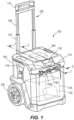
- the depicted power supply 100 is configured to be ingress protected.
- Ingress protection refers to a sealing protection of an electronic component against an intrusion of solids and/or liquids using a sealed enclosure for the component.
- a sealed enclosure is used to prevent ingress.
- Enclosures that are ingress protected additionally have an ingress protection rating, or an IP rating.
- the power supply 100 includes an IP rating. In other words, the entire power supply 100 system has an overall IP rating. Additionally, subsystems within the power supply 100 each have an individual IP rating, as explained below.
- IP ratings as used herein can be defined by international standards, such as International Electrotechnical Commission 60529, which classifies and provides a guideline to the degree of protection provided by mechanical casings and electrical enclosures against the intrusion of dust, accidental contact, and water. IP ratings are not necessarily linear. For example, a component may be IPX7 rated, however, the component may fail the IPX6 rating test. Failing the IPX6 rating test does not impact the IPX7 rating. In other words, each ingress protection rating includes individual and distinct test(s).
- the power supply 100 includes, among other things, a housing 102.
- the housing 102 includes one or more wheels 104 and a handle assembly 106.
- the handle assembly 106 is a telescoping handle movable between an extended position and a collapsed position.
- the handle assembly 106 includes an inner tube 108 and an outer tube 110.
- the inner tube 108 fits inside the outer tube 110 and is slidable relative to the outer tube 110.
- the inner tube 108 is coupled to a horizontal holding member 112.
- the handle assembly 106 further includes a locking mechanism to prevent inner tube 108 from unintentionally moving relative to the outer tube 110.
- the locking mechanism may include notches, sliding catch pins, or another suitable locking mechanism to inhibit the inner tube 108 from sliding relative to the outer tube 110 when the handle assembly 106 is in the extended position and/or in the collapsed position.
- a user holds the horizontal holding member 112 and pulls upward to extend the handle assembly 106.
- the inner tube 108 slides relative to the outer tube 110 until the handle assembly 106 locks in the extended position.
- the user may then pull and direct the power supply 100 by the handle assembly 106 to a desired location.
- the wheels 104 of the power supply 100 facilitate such movement.
- the housing 102 additionally includes perforation(s) along select components of the housing 102. In other embodiments, the housing 102 may not include perforation(s).
- the housing 102 of the power supply 100 further includes a power input unit 114, a power output unit 116, and a display 118.
- the power input unit 114 includes multiple electrical connection interfaces configured to receive power from an external power source.
- the external power source is a DC power source.
- the DC power source may be one or more photovoltaic cells (e.g., a solar panel), an electric vehicle (EV) charging station, or any other DC power source.
- the external power source is an AC power source.
- the AC power source may be a conventional wall outlet, such as a 120 V outlet or a 240 V outlet, found in North America.
- the AC power source may be a conventional wall outlet, such as a 220V outlet or 230V outlet, found outside of North America.
- the power input unit 114 is replaced by or additionally includes a cable configured to plug into a conventional wall outlet.
- the power input unit 114 further includes one or more devices, such as antennas or induction coils, configured to wirelessly receive power from an external power source.
- the power received by the power input unit 114 may be used to charge a core battery, or internal power source 120, disposed within the housing 102 of power supply 100.
- the power input unit 114 charges the internal power source 120 via a charger 122 located within the housing 102.
- the power received by the power input unit 114 may also be used to provide power to one or more devices connected to the power output unit 116.
- the power output unit 116 includes one more power outlets.
- the power output unit 116 includes a plurality of AC power outlets 116A and DC power outlets 116B. It should be understood that number of power outlets included in the power output unit 116 is not limited to the power outlets illustrated in FIG. 1 .
- the power output unit 116 may include more or fewer power outlets than the power outlets included in the illustrated embodiment of power supply 100.
- the power output unit 116 is configured to provide power output by the internal power source 120 to one or more peripheral devices.
- the power output unit 116 is also configured to provide power output by the internal power source 120.
- the power output unit 116 is configured to provide power provided by an external power source directly to one or more peripheral devices.
- the one or more peripheral devices may be a smartphone, a tablet computer, a laptop computer, a portable music player, a power tool, a power tool battery pack, a power tool battery pack charger, or the like.
- the peripheral devices may be configured to receive DC and/or AC power from the power output unit 116.
- the DC power outlets 116B include one or more receptacles for receiving and charging power tool battery packs.
- power tool battery packs received by, or connected to, the DC power outlets 116B are charged with power output by the internal power source 120 and/or power received directly from the external power source.
- power tool battery packs connected to the DC power outlets 116B are used to provide power to the internal power source 120 and/or one or more peripheral devices connected to outlets of the power output unit 116.
- the power output unit 116 includes tool-specific power outlets.
- the power output unit may include a DC power outlet used for powering a welding tool.
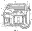
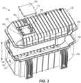
- the internal power source 120 may be disposed in a power source enclosure 124 and acts as a first subsystem of the power supply 100.
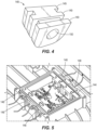
- the power source enclosure 124 includes a body 128 having a depth, D, and a lid 132, with the lid 132 being separable from the body 128. When the lid 132 is in contact with the body 128, the body 128 and the lid 132 are in contact along a body edge 136 and a lid edge 140, respectively.
- the power source enclosure 124 additionally includes a gasket 144 and a grommet 148 disposed between the body edge 136 and the lid edge 140.
- the gasket 144 follows an outline of the body edge 136 and is configured to seal the lid edge 140 to the body edge 136 when the lid 132 is disposed on the body 128.
- the grommet 148 allows wires to pass through a wall of the body 128 when the body 128 and the lid 132 are sealed via the gasket 144.
- the grommet 148 additionally facilitates in sealing the lid 132 to the body 128.
- the power source enclosure 124 may include multiple grommets disposed between the body edge 136 and the lid edge 140. In other embodiments, the power source enclosure 124 may include solely one grommet disposed between the body edge 136 and the lid edge 140.
- the grommet 148 is shown in FIG. 4 .
- the grommet 148 includes ridges 149 and a center hole 150.
- the wire (not shown) is disposed in the center hole 150.
- the ridges 149 provide a counteracting force to stop the grommet 148 from being dislocated from the body edge 136.
- the ridges 149 additionally direct any non-desirable liquid to pass through multiple dips prior to entering the power source enclosure 124. Therefore, liquid intrusion into the power source enclosure 124 through the grommet 148 is minimized or prevented.
- the gasket 144 and the grommet(s) 148 are shown in FIG. 5 . Including both the gasket 144 and the grommet(s) 148 on the body edge 136 facilitates greater ingress protection of the power source enclosure 124 than a typical enclosure.
- the body 128 can include a gore valve 152 ( FIG. 3 ) disposed in a wall of the body 128.
- the gore valve 152 provides pressure equalization.
- the gore valve 152 allows air to flow freely in and out of the power source enclosure 124, equalizing a pressure within the power source enclosure 124 and a pressure outside of the power source enclosure 124.
- the gore valve 152 is additionally configured to block liquids, dust, and contaminants from entering the power source enclosure 124 through the gore valve 152.
- the lid 132 includes a window 156 having a detachable window lid 160.
- the lid 132 further includes the gasket 144 and the grommet(s) 148 disposed between an edge 168 of the window 156 and an edge 172 of the window lid 160.
- the gasket 144 and grommet(s) 148 disposed between the window 156 and the window lid 160 seal the window lid 160 to the window 156.
- the grommet(s) 148 allow wires to pass through a surface of the lid 132 while sealing the window lid 160 to the window 156.
- the lid 132 may include multiple grommets disposed between the window 156 and the window lid 160. In other embodiments, the lid 132 may include solely one grommet disposed between the window 156 and the window lid 160.
- Ingress protection refers to protection of electronic(s) against solids and liquids by an electrical enclosure.
- the power source enclosure 124 includes an ingress protection rating, or IP rating, of IP 67.
- IP 67 means that ingress of water in harmful quantities is not permitted to enter the enclosure when the enclosure is immersed in water under defined conditions of pressure and time. Additionally, IP67 means that the enclosure is dust-tight such that no dust enters the enclosure.
- the IP rating of the power source enclosure 124 may be less than IP67. In other embodiments, the IP rating of the power source enclosure 124 may be greater than IP67.
- the charger enclosure may have an IP rating that is within the range of IP44 to IP69k (e.g., IP44, IP45, IP46, IP47, IP48, IP49k, IP54, IP55, IP56, IP57, IP58, IP59k, IP64, IP65, IP66, IP67, IP68, IP69k).
- IP44 IP45, IP46, IP47, IP48, IP49k, IP54, IP55, IP56, IP57, IP58, IP59k, IP64, IP65, IP66, IP67, IP68, IP69k.
- a portion of the power source enclosure 124 may be removed such that the power source enclosure 124 is solely ingress protected when the power source enclosure 124 is mounted in the power supply 100.
- the lid 132 of the power source enclosure 124 may be removed such that the body of the power source enclosure 124 seals to a surface of the housing.
- the charger 122 is disposed in a charger enclosure 176 and acts as a second subsystem of the power supply 100.
- the charger enclosure 176 is operationally similar to the power source enclosure 124, described above.
- the charger enclosure 176 includes a body 180 and a lid 184. When the lid 184 is in contact with the body 180, the body 180 and the lid 184 are in contact along a body edge 188 and a lid edge 192, respectively.
- the charger enclosure 176 additionally includes a gasket 196 and grommet(s) 200 disposed between the body edge 188 and the lid edge 192.
- the gasket 196 follows an outline of the body edge 188 and is configured to seal the lid edge 192 to the body edge 188 when the lid 184 is disposed on the body 180.
- the grommet(s) 200 allows wires to pass through a wall of the body 180 when the body 180 and the lid 184 are sealed via the gasket 196.
- the grommet(s) 200 additionally facilitates in sealing the lid 184 to the body 180.
- the charger enclosure 176 may include multiple grommets disposed between the body edge 188 and the lid edge 192. In other embodiments, the charger enclosure 176 may include solely one grommet disposed between the body edge 188 and the lid edge 192.
- the charger enclosure 176 includes an IP rating of IP66.
- IP 66 means that water projected in powerful jets from any direction will not have harmful effects electronics held within the enclosure.
- IP66 additionally means that the enclosure is dust-tight such that no dust enters the enclosure.
- the IP rating of the charger enclosure 176 may be less than IP66.
- the IP rating of the charger enclosure 176 may be greater than IP66.
- the charger enclosure may have an IP rating that is within the range of IP44 to IP66 (e.g., IP44, IP45, IP46, IP54, IP55, IP56, IP64, IP65, IP66).
- the IP ratings of the charger are with respect to the electronic board with in the charger enclosure 176 and not for the entire charger subsystem.
- the charger enclosure 176 may be ingress protected individually. In other words, the charger enclosure 176 is ingress protected whether the charger enclosure 176 is mounted within the power supply 100 or is separate from the power supply 100. In some aspects, a portion of the charger enclosure 176 may be removed such that the charger enclosure 176 is solely ingress protected when the charger enclosure 176 is mounted in the power supply 100. For example, the lid of the charger enclosure 176 may be removed such that the body of the charger enclosure 176 seals to a surface of the housing.
- the DC power outlets may additionally include USB connectors 204, outlets, or the like that act as a third subsystem of the power supply 100.
- the USB connectors 204 are housed in a compartment 208 positioned proximate the display 118.
- the compartment 208 includes a door 212 that pivots about a pivot axis.
- the door 212 includes a latch configured to hold the door 212 in a closed position when the latch is in a latched position.
- the latch is movable to an unlatched position where the door 212 is movable to an open position.
- the latch includes a gasket 214 configured to prevent liquid and debris from entering the compartment 208 through the latch when the latch is in the latched position.
- the door 212 may include additional gaskets to provide further ingress protection.
- the USB connectors 204 include a USB board 216.
- the USB board 216 may be potted and coated such that liquid and debris are prevented from coming into contact with electronics on the USB board 216.
- the USB board 216 additionally is oriented such that liquid and debris is diverted away from the USB board 216.
- the USB connectors 204 include an IP rating of IP64.
- IP64 means that ingress of water in harmful quantities is not permitted to enter the enclosure when the enclosure is immersed in water under defined conditions of pressure and time. Additionally, IP64 means that the enclosure is dust-tight such that no dust enters.
- the IP rating of the USB connectors 204 may be less than IP64. In other embodiments, the IP rating of the USB connectors 204 may be greater than IP64.
- the USB connectors may have an IP rating that is within the range of IP32 to IP66 (e.g., IP32, IP33, IP34, IP35, IP36, IP42, IP43, IP44, IP45, IP46, IP52, IP53, IP54, IP55, IP56, IP62, IP63, IP64, IP65, IP66).
- IP32 to IP66 e.g., IP32, IP33, IP34, IP35, IP36, IP42, IP43, IP44, IP45, IP46, IP52, IP53, IP54, IP55, IP56, IP62, IP63, IP64, IP65, IP66.
- the USB connectors 204 are ingress protected when disposed in the compartment 208. In other words, the USB connectors 204 are ingress protected solely when the USB connectors 204 are disposed in the power supply 100. In some embodiments, the USB connectors 204 may be individually ingress protected such that the USB connectors 204 are ingress protected when disposed outside of the power supply 100.
- the display 118 is configured to indicate a state of the power supply 100 to a user, such as state of charge of the internal power source 120 and/or fault conditions.
- the display acts as a fourth subsystem of the power supply 100 and as a human-machine interface.
- the display 118 can include a button or switch configured to turn on the power unit, turn off the power unit, and similar operations.
- the display 118 includes one or more light-emitting diode (“LED") indicators configured to illuminate and display a current state of charge of internal power source 120.
- the display 118 includes a board 220, a screen 224, and a display housing 228. The board 220 controls operation of the display 118.
- the board 220 is, for example, a liquid crystal display (“LCD”) board, a light-emitting diode (“LED”) display board, an organic LED (“OLED”) display board, an electroluminescent display (“ELD”) board, a surface-conduction electron-emitter display (“SED”) board, a field emission display (“FED”) board, a thin-film transistor (“TFT”) LCD board, etc.
- the screen 224 is coupled to the display housing 228 such that a space is formed between the screen 224 and a surface of the display housing 228.
- the board 220 is disposed in the space between the screen 224 and the display housing 228.
- the display 118 is directly coupled to the housing 102 such that the display 118 is visible to the user.
- the screen 224 of the display 118 interacts with a surface of the housing 102.
- the screen 224 is enclosed in a gasket 232 such that the spaces between the screen 224, the display housing 228, and the housing 102 are sealed.
- the board 220 of the display 118 may be encapsulated in a coating, such as a coating that prevents liquid and debris from interfering with electronics on the board.
- the board 220 may be coated in an alternative coating. In other embodiments, the board 220 may not be coated.
- the display housing 228 additionally includes grommet(s) 236 disposed at a bottom surface of the display housing 228.
- the grommet(s) 236 allow wires to pass through the bottom surface of the display housing 228.
- the grommet(s) 236 additionally provide sealing for the display housing 228 such that liquid and debris are prevented from entering the display housing 228 through the grommet(s) 236.
- the display housing 228 may include multiple grommets. In other embodiments, the display housing 228 may include solely one grommet disposed between the body edge 136 and the lid edge 140.
- the display 118 may be detached from the housing 102.
- the internal power source 120 (see FIGS. 1 to 3 ) may remotely communicate with the display 118 through a cord, a Bluetooth connection, or the like.
- the human-machine interface includes an application software program, or app, executable on a smart device.
- the app may be accessible through a cellular device, a tablet, a computer, or a similar electronic device.
- the user downloads or executes the app and connects to the power supply 100 via the Bluetooth connection or the cord.
- the human-machine interface is visible on the app.
- the user may power on and off the internal power source 120 by pushing a representation of a button displayed on the smart device.
- the human-machine interface may be remotely accessible through a website link, or a similar program.
- the power supply 100 additionally includes an inverter 240 configured to convert low-voltage DC power from the power input unit to AC power.
- the inverter 240 acts as a fifth subsystem of the power supply 100 and includes an inverter enclosure 244 which houses an inverter board.
- the inverter enclosure 244 includes parallel side panels 248.
- the parallel side panels 248 are perforated such that air is permitted to flow through the parallel side panels.
- the parallel side panels 248 include louvered vents 252 configured to divert liquid and debris away from the inverter enclosure 244.
- the inverter board is potted such that liquid and debris is prevented from interacting with electronics on the inverter board.
- the inverter board may be coated such that liquid and debris are prevented from interacting with the electronics on the inverter board.
- the inverter board may not include a coating or potting.
- the inverter 240 includes an IP rating of IP66.
- the IP rating of the inverter 240 may be less than IP66.
- the IP rating of the inverter 240 may be greater than IP66.
- the inverter 240 is ingress protected whether the inverter 240 is mounted within the power supply 100 or is separate from the power supply 100.
- a portion of the inverter enclosure 244 may be removed such that the inverter 240 is solely ingress protected when the inverter 240 is mounted in the power supply 100.
- the inverter 240 may have an IP rating that is within the range of IP32 to IP66 (e.g., IP32, IP33, IP34, IP35, IP36, IP42, IP43, IP44, IP45, IP46, IP52, IP53, IP54, IP55, IP56, IP62, IP63, IP64, IP65, IP66).
- IP32 to IP66 e.g., IP32, IP33, IP34, IP35, IP36, IP42, IP43, IP44, IP45, IP46, IP52, IP53, IP54, IP55, IP56, IP62, IP63, IP64, IP65, IP66.
- the subsystems of the power supply 100 are electrically connected via a series of wires.
- a first subsystem positioned with the housing 102 may be electrically connected to a power source 120 of the power supply 100 using a daisy-chain type connection through a second subsystem positioned in the housing 102 where the second subsystem is directly connected to the power source 120.
- the wires may be encapsulated in a heat shrink tube such that the wires are ingress protected.
- any cables or wires that connect the power supply 100 to the external power source are encapsulated in a heat shrink tube such that the cables or wires are ingress protected. Due to the heat shrink, the wires have an IP rating that ranges from IP54 to IP68. In other aspects, an IP rating may be obtained for the wires without the use of heat shrink tubing, such as through the use of IP rated connectors.
- connectors for wire may be ingress protected through the use of dielectric grease or other methods.
- the subsystems are arranged within the power supply 100 such that one or more channels, such as channels 256a-256e, are formed between the subsystems.
- the channel 256c may be formed around the power source enclosure 124 such that the power source enclosure 124 is positioned on a first side 257 of the channel 256c and the charger 122, the USB connectors 204, the inverter 240, and the housing 102 are positioned on a second side 258 of the channel 256c that is opposite the first side 257.
- the channel 256c routes the liquid and debris over a lip 260 of the power source enclosure 124 such that the liquid and debris does not interact with the gasket 144 of the power source enclosure 124.
- the channel(s) 256a-256e route liquid and debris to weep holes 264 such that liquid and debris, or ingress, does not accumulate within the power supply 100.
- the weep holes 264 are positioned in a lower wall 268 (shown in FIG. 11 ) of the housing 102. Liquid and debris exits the weep holes 264, such as weep holes 264a-264f, when the housing 102 is in a static use mode (shown in FIG. 11 ) and a transportation mode (shown in FIG. 12 ).
- the lower wall 268 In the static use mode, the lower wall 268 is parallel with a ground surface 272. In other words, in the static use mode, an angle between the ground surface 272 and the lower wall 268 is between -10 degrees and 10 degrees.
- the lower wall 268 is angled (shown in FIG. 12 ) relative to the ground surface 272 such that an angle between the ground surface 272 and the lower wall 268 is greater than 10 degrees or less than -10 degrees.
- the housing 102 is titled such that the wheel 104 facilitates movement of the power supply 100.
- the weep holes 264 allow liquid and/or debris to exit the housing 102 in both the static and transportation modes.
- the power supply may include more than or less than five subsystems.
- a power supply can include three subsystems, four subsystems, five subsystems, six subsystem, or seven subsystems.
- the arrangement of subsystems may be different than the arrangement described above.
- aspects described herein provide, among other things, a power supply including multiple subsystems that are ingress protected.
- Various features and advantages are set forth in the following claims.
- the terms “comprises” and “comprising” and variations thereof mean that the specified features, steps or integers are included. The terms are not to be interpreted to exclude the presence of other features, steps or components.
Landscapes
- Engineering & Computer Science (AREA)
- Chemical & Material Sciences (AREA)
- Chemical Kinetics & Catalysis (AREA)
- Electrochemistry (AREA)
- General Chemical & Material Sciences (AREA)
- Power Engineering (AREA)
- Microelectronics & Electronic Packaging (AREA)
- Human Computer Interaction (AREA)
- Charge And Discharge Circuits For Batteries Or The Like (AREA)
- Telephone Set Structure (AREA)
- Casings For Electric Apparatus (AREA)
Applications Claiming Priority (2)
| Application Number | Priority Date | Filing Date | Title |
|---|---|---|---|
| US202263356099P | 2022-06-28 | 2022-06-28 | |
| US202263371240P | 2022-08-12 | 2022-08-12 |
Publications (2)
| Publication Number | Publication Date |
|---|---|
| EP4311383A2 true EP4311383A2 (fr) | 2024-01-24 |
| EP4311383A3 EP4311383A3 (fr) | 2024-03-20 |
Family
ID=87047564
Family Applications (1)
| Application Number | Title | Priority Date | Filing Date |
|---|---|---|---|
| EP23181316.3A Pending EP4311383A3 (fr) | 2022-06-28 | 2023-06-23 | Alimentation électrique comprenant une protection d'entrée |
Country Status (2)
| Country | Link |
|---|---|
| US (1) | US20230420777A1 (fr) |
| EP (1) | EP4311383A3 (fr) |
Family Cites Families (7)
| Publication number | Priority date | Publication date | Assignee | Title |
|---|---|---|---|---|
| CA2747585C (fr) * | 2010-07-27 | 2020-05-26 | Ark Corporation Pty Ltd | Chargeur et bloc d'alimentation portable |
| US20130164567A1 (en) * | 2011-06-24 | 2013-06-27 | Seektech, Inc. | Modular battery pack apparatus, systems, and methods |
| US20130273396A1 (en) * | 2012-04-16 | 2013-10-17 | Central Garden & Pet Company | Battery box |
| US9966641B2 (en) * | 2015-12-29 | 2018-05-08 | Lg Chem, Ltd. | Battery pack |
| US20190181407A1 (en) * | 2017-12-11 | 2019-06-13 | Romeo Systems, Inc. | Shock absorbant and water-resistant portable energy storage device |
| EP3735731B1 (fr) * | 2018-01-02 | 2025-08-27 | Worldwide Energy LLC | Alimentation électrique portable |
| EP4483681A1 (fr) * | 2022-02-25 | 2025-01-01 | Signify Holding B.V. | Dispositif électrique avec matériau d'enrobage |
-
2023
- 2023-06-23 EP EP23181316.3A patent/EP4311383A3/fr active Pending
- 2023-06-23 US US18/340,081 patent/US20230420777A1/en active Pending
Also Published As
| Publication number | Publication date |
|---|---|
| EP4311383A3 (fr) | 2024-03-20 |
| US20230420777A1 (en) | 2023-12-28 |
Similar Documents
| Publication | Publication Date | Title |
|---|---|---|
| EP2842795B1 (fr) | Station de charge de véhicule électrique avec options et procédés d'installation électrique reconfigurable | |
| EP2617600A2 (fr) | Stations de charge pour charger des véhicules électriques et procédés associés | |
| US11552460B2 (en) | Electrical panel adapter providing pass through access to electrical signals within an enclosure | |
| US20160359307A1 (en) | Access windows in horizontal bar section of an electrical meter center | |
| JP2014180733A (ja) | 筐体 | |
| WO2017155855A1 (fr) | Boîte de jonction | |
| EP4311383A2 (fr) | Alimentation électrique comprenant une protection d'entrée | |
| US10601204B2 (en) | Electrical unit for a motor control center with ingress protection | |
| JP6767817B2 (ja) | ガス検知装置 | |
| PL83637B1 (fr) | ||
| US9667041B2 (en) | Electrically insulating cover for terminal assembly | |
| CN220554191U (zh) | 便携式供电设备 | |
| JP5638726B1 (ja) | ガス絶縁スイッチギヤ | |
| US20180138668A1 (en) | Insulated Electrical Switch Cabinet Cover | |
| CA2308792C (fr) | Disjoncteur | |
| CA2935842C (fr) | Panneau modulaire sans porte | |
| WO2016185719A1 (fr) | Système de stockage d'énergie | |
| CN216700643U (zh) | 一种应急电源箱及消防应急集中电源 | |
| CN210923843U (zh) | 一种电力监测装置 | |
| US7814341B1 (en) | Power supply | |
| JP2018194368A (ja) | キャビネット | |
| JP2005051909A (ja) | 分電盤装置 | |
| US20220224097A1 (en) | Cable-entry device for an electronic chassis | |
| CN208638835U (zh) | 电气控制操作装置及电气控制操作系统 | |
| KR102851602B1 (ko) | 와이어 하네스 |
Legal Events
| Date | Code | Title | Description |
|---|---|---|---|
| PUAI | Public reference made under article 153(3) epc to a published international application that has entered the european phase |
Free format text: ORIGINAL CODE: 0009012 |
|
| STAA | Information on the status of an ep patent application or granted ep patent |
Free format text: STATUS: THE APPLICATION HAS BEEN PUBLISHED |
|
| AK | Designated contracting states |
Kind code of ref document: A2 Designated state(s): AL AT BE BG CH CY CZ DE DK EE ES FI FR GB GR HR HU IE IS IT LI LT LU LV MC ME MK MT NL NO PL PT RO RS SE SI SK SM TR |
|
| PUAL | Search report despatched |
Free format text: ORIGINAL CODE: 0009013 |
|
| AK | Designated contracting states |
Kind code of ref document: A3 Designated state(s): AL AT BE BG CH CY CZ DE DK EE ES FI FR GB GR HR HU IE IS IT LI LT LU LV MC ME MK MT NL NO PL PT RO RS SE SI SK SM TR |
|
| RIC1 | Information provided on ipc code assigned before grant |
Ipc: H05K 5/06 20060101ALI20240213BHEP Ipc: H02J 7/00 20060101ALI20240213BHEP Ipc: H05K 7/14 20060101AFI20240213BHEP |
|
| STAA | Information on the status of an ep patent application or granted ep patent |
Free format text: STATUS: REQUEST FOR EXAMINATION WAS MADE |
|
| 17P | Request for examination filed |
Effective date: 20240904 |
|
| RBV | Designated contracting states (corrected) |
Designated state(s): AL AT BE BG CH CY CZ DE DK EE ES FI FR GB GR HR HU IE IS IT LI LT LU LV MC ME MK MT NL NO PL PT RO RS SE SI SK SM TR |