EP4311590B1 - Filtre a air - Google Patents
Filtre a air Download PDFInfo
- Publication number
- EP4311590B1 EP4311590B1 EP23176673.4A EP23176673A EP4311590B1 EP 4311590 B1 EP4311590 B1 EP 4311590B1 EP 23176673 A EP23176673 A EP 23176673A EP 4311590 B1 EP4311590 B1 EP 4311590B1
- Authority
- EP
- European Patent Office
- Prior art keywords
- filter
- wedge
- filter element
- clamping
- mounting frame
- Prior art date
- Legal status (The legal status is an assumption and is not a legal conclusion. Google has not performed a legal analysis and makes no representation as to the accuracy of the status listed.)
- Active
Links
Images



Classifications
-
- B—PERFORMING OPERATIONS; TRANSPORTING
- B01—PHYSICAL OR CHEMICAL PROCESSES OR APPARATUS IN GENERAL
- B01D—SEPARATION
- B01D46/00—Filters or filtering processes specially modified for separating dispersed particles from gases or vapours
- B01D46/0002—Casings; Housings; Frame constructions
- B01D46/0013—Modules
-
- B—PERFORMING OPERATIONS; TRANSPORTING
- B01—PHYSICAL OR CHEMICAL PROCESSES OR APPARATUS IN GENERAL
- B01D—SEPARATION
- B01D46/00—Filters or filtering processes specially modified for separating dispersed particles from gases or vapours
- B01D46/10—Particle separators, e.g. dust precipitators, using filter plates, sheets or pads having plane surfaces
-
- B—PERFORMING OPERATIONS; TRANSPORTING
- B60—VEHICLES IN GENERAL
- B60H—ARRANGEMENTS OF HEATING, COOLING, VENTILATING OR OTHER AIR-TREATING DEVICES SPECIALLY ADAPTED FOR PASSENGER OR GOODS SPACES OF VEHICLES
- B60H3/00—Other air-treating devices
- B60H3/06—Filtering
- B60H3/0608—Filter arrangements in the air stream
- B60H3/0616—Filter arrangements in the air stream with provisions for replacing the filter element
-
- B—PERFORMING OPERATIONS; TRANSPORTING
- B01—PHYSICAL OR CHEMICAL PROCESSES OR APPARATUS IN GENERAL
- B01D—SEPARATION
- B01D46/00—Filters or filtering processes specially modified for separating dispersed particles from gases or vapours
- B01D46/0002—Casings; Housings; Frame constructions
- B01D46/0005—Mounting of filtering elements within casings, housings or frames
-
- B—PERFORMING OPERATIONS; TRANSPORTING
- B01—PHYSICAL OR CHEMICAL PROCESSES OR APPARATUS IN GENERAL
- B01D—SEPARATION
- B01D46/00—Filters or filtering processes specially modified for separating dispersed particles from gases or vapours
- B01D46/0002—Casings; Housings; Frame constructions
- B01D46/0005—Mounting of filtering elements within casings, housings or frames
- B01D46/0006—Filter elements or cartridges installed in a drawer-like manner
-
- B—PERFORMING OPERATIONS; TRANSPORTING
- B01—PHYSICAL OR CHEMICAL PROCESSES OR APPARATUS IN GENERAL
- B01D—SEPARATION
- B01D46/00—Filters or filtering processes specially modified for separating dispersed particles from gases or vapours
- B01D46/0039—Filters or filtering processes specially modified for separating dispersed particles from gases or vapours with flow guiding by feed or discharge devices
-
- B—PERFORMING OPERATIONS; TRANSPORTING
- B01—PHYSICAL OR CHEMICAL PROCESSES OR APPARATUS IN GENERAL
- B01D—SEPARATION
- B01D46/00—Filters or filtering processes specially modified for separating dispersed particles from gases or vapours
- B01D46/0084—Filters or filtering processes specially modified for separating dispersed particles from gases or vapours provided with safety means
- B01D46/0087—Bypass or safety valves
-
- B—PERFORMING OPERATIONS; TRANSPORTING
- B01—PHYSICAL OR CHEMICAL PROCESSES OR APPARATUS IN GENERAL
- B01D—SEPARATION
- B01D46/00—Filters or filtering processes specially modified for separating dispersed particles from gases or vapours
- B01D46/10—Particle separators, e.g. dust precipitators, using filter plates, sheets or pads having plane surfaces
- B01D46/12—Particle separators, e.g. dust precipitators, using filter plates, sheets or pads having plane surfaces in multiple arrangements
-
- B—PERFORMING OPERATIONS; TRANSPORTING
- B01—PHYSICAL OR CHEMICAL PROCESSES OR APPARATUS IN GENERAL
- B01D—SEPARATION
- B01D46/00—Filters or filtering processes specially modified for separating dispersed particles from gases or vapours
- B01D46/52—Particle separators, e.g. dust precipitators, using filters embodying folded corrugated or wound sheet material
- B01D46/521—Particle separators, e.g. dust precipitators, using filters embodying folded corrugated or wound sheet material using folded, pleated material
-
- B—PERFORMING OPERATIONS; TRANSPORTING
- B01—PHYSICAL OR CHEMICAL PROCESSES OR APPARATUS IN GENERAL
- B01D—SEPARATION
- B01D46/00—Filters or filtering processes specially modified for separating dispersed particles from gases or vapours
- B01D46/56—Filters or filtering processes specially modified for separating dispersed particles from gases or vapours with multiple filtering elements, characterised by their mutual disposition
- B01D46/62—Filters or filtering processes specially modified for separating dispersed particles from gases or vapours with multiple filtering elements, characterised by their mutual disposition connected in series
-
- B—PERFORMING OPERATIONS; TRANSPORTING
- B01—PHYSICAL OR CHEMICAL PROCESSES OR APPARATUS IN GENERAL
- B01D—SEPARATION
- B01D46/00—Filters or filtering processes specially modified for separating dispersed particles from gases or vapours
- B01D46/56—Filters or filtering processes specially modified for separating dispersed particles from gases or vapours with multiple filtering elements, characterised by their mutual disposition
- B01D46/62—Filters or filtering processes specially modified for separating dispersed particles from gases or vapours with multiple filtering elements, characterised by their mutual disposition connected in series
- B01D46/64—Filters or filtering processes specially modified for separating dispersed particles from gases or vapours with multiple filtering elements, characterised by their mutual disposition connected in series arranged concentrically or coaxially
-
- B—PERFORMING OPERATIONS; TRANSPORTING
- B60—VEHICLES IN GENERAL
- B60H—ARRANGEMENTS OF HEATING, COOLING, VENTILATING OR OTHER AIR-TREATING DEVICES SPECIALLY ADAPTED FOR PASSENGER OR GOODS SPACES OF VEHICLES
- B60H3/00—Other air-treating devices
- B60H3/06—Filtering
- B60H3/0658—Filter elements specially adapted for their arrangement in vehicles
-
- B—PERFORMING OPERATIONS; TRANSPORTING
- B01—PHYSICAL OR CHEMICAL PROCESSES OR APPARATUS IN GENERAL
- B01D—SEPARATION
- B01D2265/00—Casings, housings or mounting for filters specially adapted for separating dispersed particles from gases or vapours
- B01D2265/02—Non-permanent measures for connecting different parts of the filter
- B01D2265/024—Mounting aids
- B01D2265/025—Mounting aids making use of ramps or cams
-
- B—PERFORMING OPERATIONS; TRANSPORTING
- B01—PHYSICAL OR CHEMICAL PROCESSES OR APPARATUS IN GENERAL
- B01D—SEPARATION
- B01D2265/00—Casings, housings or mounting for filters specially adapted for separating dispersed particles from gases or vapours
- B01D2265/02—Non-permanent measures for connecting different parts of the filter
- B01D2265/027—Quick closing means for, e.g. filter heads, caps, maintenance openings
-
- B—PERFORMING OPERATIONS; TRANSPORTING
- B01—PHYSICAL OR CHEMICAL PROCESSES OR APPARATUS IN GENERAL
- B01D—SEPARATION
- B01D2265/00—Casings, housings or mounting for filters specially adapted for separating dispersed particles from gases or vapours
- B01D2265/02—Non-permanent measures for connecting different parts of the filter
- B01D2265/028—Snap, latch or clip connecting means
-
- B—PERFORMING OPERATIONS; TRANSPORTING
- B01—PHYSICAL OR CHEMICAL PROCESSES OR APPARATUS IN GENERAL
- B01D—SEPARATION
- B01D2273/00—Operation of filters specially adapted for separating dispersed particles from gases or vapours
- B01D2273/10—Allowing a continuous bypass of at least part of the flow, e.g. of secondary air, vents
-
- B—PERFORMING OPERATIONS; TRANSPORTING
- B01—PHYSICAL OR CHEMICAL PROCESSES OR APPARATUS IN GENERAL
- B01D—SEPARATION
- B01D2277/00—Filters specially adapted for separating dispersed particles from gases or vapours characterised by the position of the filter in relation to the gas stream
- B01D2277/20—Inclined, i.e. forming an angle of between 0° and 90°
Definitions
- the invention relates to an air filter with a first and a second filter element.
- Such high-efficiency air filters are known to the applicant (but not necessarily published) and are used, for example, to filter air for vehicle interiors.
- the air filters used typically have a filter element for pre-separating coarse contaminants in the air to be filtered and a high-separating filter element, for example a suspended matter filter, for separating small contaminants.
- the filter elements are therefore usually arranged within the air filter in such a way that the air to be filtered flows first through the filter element for pre-separating and then through the filter element for separating small contaminants. Examples of air filters with two filter elements are given in the US2017/095761 and the US2018/345196 revealed.
- the air filter often has to be laboriously removed from the air duct. This increases the amount of work required to change the filter elements.
- some air filters have a side service opening that allows the filter elements to be changed while the air filter is installed.
- the filter elements in these air filters can be replaced via the side service opening across the flow direction of the filter elements.
- the conventional systems are only suitable to a limited extent, especially when using a high-efficiency filter element. This is because the filter elements used have high requirements for their sealing in order to prevent air from flowing around the filter element.
- the necessary contact pressure of the filter elements between the filter elements and between the filter elements and/or the filter housing cannot be achieved sufficiently with the conventional systems.
- leakage currents can arise within the air filter, which allow unfiltered air to bypass. Furthermore, these leakage currents can cause unwanted, annoying flow noises that penetrate into the vehicle interior.
- an air filter has a filter housing with an inlet opening on the raw air side, at least one outlet opening on the clean air side and a closable maintenance opening.
- the maintenance opening is preferably designed to be hermetically sealed.
- the air filter also has a first filter element and a second filter element.
- the air filter can have three or more filter elements, which can improve the filtering effect.
- the air filter has exactly two filter elements.
- the filter elements are arranged between the inlet opening and the at least one outlet opening within the filter housing.
- the air filter also has a mounting frame in which the first filter element is accommodated. The filter elements can be flowed through serially or sequentially in at least one operating state of the air filter.
- the filter elements are arranged along a flow path of the air to be filtered through the filter housing.
- the mounting frame can be removed from the filter housing through the maintenance opening against a joining direction and can be inserted into the filter housing in the joining direction.
- the mounting frame also has a clamping wedge.
- the second filter element has a wedge stop. The clamping wedge of the mounting frame comes into contact with the wedge stop of the second filter element when the mounting frame is inserted, whereby the second filter element is clamped to the filter housing in a clamping direction transverse to the joining direction.
- the air filter according to the invention thus enables the filter elements to be changed particularly quickly and easily via a lateral, in particular top-side, maintenance opening.
- This means that the filter elements can be changed without removing the air filter from an air duct system, for example a system for ventilating a vehicle interior.
- the air filter according to the invention can be used to clamp the filter elements transversely to the joining direction. This means that the filter elements can be pressed in the clamping direction despite the filter elements being inserted sideways.
- the contact pressure of the filter elements on the filter housing that is necessary for sealing can be achieved in this way.
- the air filter according to the invention therefore has a particularly high seal between the filter elements and the filter housing and can effectively prevent leakage flows.
- the joining direction is the assembly direction of the filter elements in which the filter elements are inserted into the filter housing.
- the clamping direction is the direction of action of the clamping force caused by the clamping wedge, with which the assembly frame is clamped to the second filter element and the filter housing, and the second filter element is clamped to the filter housing.
- the clamping wedge preferably has a wedge angle.
- the wedge angle is measured between two wedge sides.
- One wedge side is typically aligned in the joining direction.
- the other wedge side can thus run at an angle to the joining direction at the wedge angle.
- the wedge sides are preferably to be understood as the sections formed by the effective contact surfaces of the clamping wedge with the wedge stop and the filter housing.
- the mounting frame can have a wedge counter-stop on a side facing away from the clamping wedge.
- the wedge counter-stops are preferably formed on the mounting frame.
- the wedge counter-stop can be supported on the filter housing in an assembled state, so that a clamping force transmitted to the second filter element via the clamping wedge can be diverted into the filter housing.
- the wedge counter-stop is preferably aligned with the clamping wedge. This allows the clamping force to be diverted particularly effectively.
- the mounting frame can have two or more, in particular four, wedge counter-stops.
- the wedge counter-stops can be arranged at a distance from one another on the mounting frame. This allows the force to be transferred into the filter housing in a particularly targeted manner.
- the filter housing can have a support surface.
- the support surface can be designed to support the mounting frame.
- the support surface preferably contacts the wedge counter-stops of the mounting frame. This allows the force dissipation points on the filter housing to be coordinated with the wedge counter-stops of the mounting frame.
- the support surface of the filter housing in conjunction with the wedge counter-stop of the mounting frame forms a key-lock principle in the joining direction.
- the clamping wedge has at least two clamping projections with a different projection height in the clamping direction.
- the clamping wedge has at least three clamping projections.
- the clamping projections can be attached or formed on the clamping wedge.
- the clamping projections can be used to specify, in particular reduce, the contact surface of the clamping wedge on the wedge stop. This can reduce the friction between the clamping wedge and the wedge stop, making it easier to insert the mounting frame.
- the wedge angle can be formed between the joining direction and a straight line running through the contact points of the clamping projections with the wedge stop.
- the projection height can be understood as the projection of the clamping projections over a common wedge base body in the clamping direction.
- the clamping projections are spaced apart from each other in the joining direction.
- a preferred development of the air filter is one in which the projection height of the clamping projections decreases in the joining direction.
- the projection height changes in the joining direction from one clamping projection to its neighboring clamping projection.
- the projection height of an individual clamping projection can be the same over its extension in the joining direction. In other words, it can be provided that the projection height on a clamping projection does not decrease in the joining direction.
- the clamping projections can form a stepped contact area on the clamping wedge.
- the wedge stop preferably has a complementary contact surface.
- the wedge stop can have stepped sections in the joining direction, each of which is contacted by a clamping projection of the clamping wedge. This allows a key-lock principle to be formed, which can prevent the use of an unsuitable or unsuitable filter element in the air filter.
- the clamping wedge has at least two wedge cheeks.
- the wedge cheeks are arranged in particular on opposite sides of the mounting frame.
- the wedge cheeks are preferably designed parallel to one another. This allows the clamping force to be applied to the second filter element as symmetrically as possible, which allows the second filter element to be pressed evenly onto the filter housing.
- the wedge stop has at least two partial stops.
- the at least two partial stops are arranged at a distance from one another on the second filter element.
- the partial stops are arranged on opposite sides of the second filter element. This can further facilitate a symmetrical and uniform pressing of the second filter element onto the filter housing.
- the partial stops are formed on a frame of the second filter element. This simplifies assembly by reducing the number of individual parts.
- the clamping wedge protrudes beyond the mounting frame in the clamping direction. In other words, the clamping wedge protrudes in the direction of the second filter element. This allows a predetermined distance to be set between the mounting frame and the second filter element. For example, this allows a flow-through volume to be provided between the first and second filter elements.
- the clamping wedge preferably overlaps the second filter element in the clamping direction. This allows the wedge stop to be arranged particularly easily on the second filter element.
- the wedge stop can protrude beyond the second filter element in the opposite direction to the clamping direction.
- the clamping wedge can rest against the wedge stop, for example, between the first filter element and the second filter element. This allows a load resulting from the clamping force to be evenly distributed between the clamping wedge and the wedge stop.
- At least one wedge cheek of the clamping wedge is designed to be fluid-permeable. This can reduce a possible flow resistance through the clamping wedge.
- the wedge cheeks protrude to different extents over the mounting frame in the clamping direction.
- This allows the mounting frame and thus the filter element accommodated therein to be arranged at an angle.
- This enables the effective filter surface of the first filter element to be increased on the one hand and the improved flow through the volume formed between the first and second filter elements on the other.
- the fluid-permeable wedge cheek protrudes further over the mounting frame than another wedge cheek. This allows the flow through capability to be further increased.
- the angled arrangement of the filter element makes it easier to provide a bypass switching element, as will be explained later.
- an embodiment of the air filter is preferred in which the first filter element is arranged replaceably on the mounting frame.
- the filter element is preferably detachably received on the mounting frame.
- the first filter element is particularly preferably in the This makes changing the first filter element particularly easy and quick.
- the filter element can, for example, have a pleated or folded filter medium.
- a particularly preferred embodiment of the air filter is one in which the mounting frame has a frame section that at least partially surrounds the first filter element on the edge, with the clamping wedge in particular being formed on the frame section.
- the frame section preferably surrounds the filter element completely. This allows the filter element to be arranged loosely on the frame section, making it particularly easy to change.
- the mounting frame preferably has at least one support grid that is arranged in the frame section.
- the support grid can prevent the filter element accommodated in the mounting frame from falling through. This allows the filter element to be arranged on the mounting frame in a way that prevents it from being lost.
- the mounting frame also preferably has two support grids, with the filter element being arranged between the two support grids in the mounting frame. This makes it possible to clean the filter on the mounting frame.
- at least one support grid is designed to be detachable from the mounting frame, which makes it possible to change the filter element.
- a further preferred embodiment of the air filter is one in which the first filter element and the second filter element are arranged parallel to one another in the assembled state. This enables uniform flow through the filter elements.
- the first filter element and the second filter element are arranged in the filter housing at an angle to one another, in particular rotated at a predetermined angle with respect to the joining direction. This allows the arrangement of the filter elements to be adapted to their inflow and/or outflow.
- the mounting frame is arranged in the assembled state at an angle to the second filter element in the filter housing, in particular rotated at a predetermined angle with respect to the joining direction. This allows the position of the mounting frame to be flexibly adapted to the available installation space for the air filter.
- a preferred embodiment of the air filter is one in which the maintenance opening can be opened and closed by a hood. This enables quick and easy access on the filter elements without dismantling the air filter.
- the hood is preferably arranged, in particular attached, to the mounting frame. This means that the mounting frame can be removed at the same time as the hood when the maintenance opening is opened.
- the maintenance opening is designed for the sequential or successive removal of the filter elements through the maintenance opening. This allows the maintenance opening to be kept small in its dimensions.
- the second filter element is rotated into a fastening position within the filter housing by means of a hinge and can be pre-fastened in the fastening position by means of a securing device, in particular a snap hook.
- the hinge preferably has hinge elements that can be detached from one another. For example, it can be provided that one partial hinge element remains in the filter housing when the filter element is removed, while another partial hinge element is removed with the filter element. The hinge can then be formed by the partial hinge elements when the filter element is inserted.
- the fastening position is to be understood as a pre-positioning of the second filter element.
- the second filter element can be placed in a predetermined position to rest on the filter housing.
- pressing can then be carried out in a particularly controlled manner.
- the insertion space for the mounting frame is increased, so that insertion can be carried out more easily.
- the air filter has a switchable bypass switching element which is located downstream of a filter element arranged upstream in a flow direction, wherein the bypass switching element is designed to cause a serial flow through both filter elements in a first operating state and to cause an at least partial bypass of the filter element arranged downstream in a second operating state.
- both filter elements are flowed through serially or one after the other if the particle concentration in the air to be filtered is high. If the particle concentration is low, in another operating state, it can be provided that one filter element is bypassed. This allows the air flow caused by this filter element to be Pressure loss can be prevented and energy consumption reduced. Furthermore, flow-related noise can be reduced.
- switching the filter elements on or off as required either the service life of the filter elements can be increased or the filter elements can be made smaller, which has a positive effect on the installation space required.
- the at least one fluid-permeable wedge cheek of the mounting frame provides a bypass flow path between the two filter elements. This enables the filter element to be bypassed with particularly low pressure loss.
- the air filter has a further outlet opening, wherein the further outlet opening is arranged on the downstream side of the first filter element, and wherein the further outlet opening can be opened and closed by the bypass switching element. This enables a particularly effective bypass of the filter element.
- the air filter has a flow guide on the clean air side, which fluidically connects the outlet openings on the downstream side.
- the flow guide preferably has a single air outlet. This makes it particularly easy to connect the air filter to an existing air duct.
- FIG. 1 shows an air filter 10 in an unassembled state.
- the air filter 10 has a filter housing 12 with an inlet opening 14 on the raw air side and an outlet opening 16 on the clean air side.
- the filter housing 12 also has a maintenance opening 18 that can be closed by a hood 20.
- the hood 20 can have a sealing means - here a circumferential sealing ring 22 - for this purpose.
- the sealing means can be arranged alternatively or additionally on the filter housing 12.
- the air filter 10 has a first filter element 24 and a second filter element 26.
- the first filter element 24 and/or the second filter element 26 can each have a frame 28. According to the illustration in Fig. 1 a possible frame 28 on the first filter element 24 is not shown in detail.
- the filter elements 24, 26 each have a folded filter medium 30. For reasons of better illustration, only a portion of the filter media 30 is shown folded. In addition, other types of filter media can be provided.
- the air filter 10 further comprises a mounting frame 32.
- the mounting frame 32 is attached to the hood 20, in particular in a non-detachable manner, as shown in the illustration.
- the hood 20 is preferably formed on the mounting frame 32. In other words, the mounting frame 32 can be moved together with the hood 20.
- the mounting frame 32 can be U-shaped, wherein the open side of the mounting frame 32 can be closed by the hood 20.
- the mounting frame 32 is designed to accommodate the first filter element 24.
- the mounting frame 32 can have a support grid 34.
- the support grid 34 is preferably on the downstream side arranged on the first filter element 24 and prevents the first filter element 24 from falling through the mounting frame 32.
- the mounting frame 32 thus supports the first filter element 24 on its circumference and on its filter surface.
- the support grid 34 preferably has a significantly higher air permeability than the first filter element 24.
- the support grid 34 is particularly preferably arranged detachably on the mounting frame 32.
- the support grid 34 can also be one-piece with the mounting frame 32 or molded onto it.
- a further support grid 34 can be arranged on the upstream side of the first filter element 24 accommodated in the mounting frame 32.
- the first filter element 24 can be arranged between two support grids 34 accommodated in the mounting frame 32. This can reliably prevent the first filter element 24 from falling out, even during intensive cleaning measures.
- the mounting frame 32 together with the first filter element 24 arranged therein, can be removed from the filter housing 12 through the maintenance opening 18 and can be inserted into the filter housing 12 in a joining direction 36.
- the filter housing 12 has a partially cut area 38 which allows a view into the filter housing 12, but is actually closed.
- the mounting frame 32 has a clamping wedge 40.
- the clamping wedge 40 can have a first wedge cheek 42 and a second wedge cheek 44 as shown.
- the second wedge cheek 44 is partially covered by the mounting frame 32 in the illustration.
- the clamping wedge 40 or each wedge cheek 42, 44 protrudes transversely, in particular at right angles, to the joining direction 36 beyond the mounting frame 32.
- the clamping wedge 40 or the wedge cheeks 42, 44 can be arranged or designed to be non-detachable on the mounting frame 32.
- the clamping wedge 40 can have a wedge angle 46 which causes a wedge height that tapers in the joining direction 36. In other words, in this case the clamping wedge 40 opens against the joining direction 36.
- the wedge cheeks 42, 44 each have a different wedge angle 46. This can increase the assembly reliability.
- the clamping wedge 40 can have clamping projections 48.
- the first wedge cheek 42 has three clamping projections 48.
- the clamping projections 48 can form the contact surface of the clamping wedge 48 with a wedge stop 50. In other words, it can be provided that the clamping wedge 40 rests against the wedge stop 50 via the clamping projections 48.
- the second filter element 26 has the wedge stop 50.
- the wedge stop 50 can be arranged or formed on the second filter element 26.
- the wedge stop 50 is arranged or formed on the frame 28 of the second filter element 26.
- the wedge stop 50 preferably has a wedge stop angle 52 which is similar to the wedge angle 46, in particular identical.
- the wedge stop 50 further preferably has a number of partial stops 54 that is identical to the number of wedge cheeks 42, 44.
- the partial stops 54 can be arranged or formed at a distance from one another on the second filter element 26.
- the partial stops 54 are particularly preferably arranged or formed on opposite sides of the second filter element 26. According to the illustration in Fig. 1 only a partial stop 54 is visible.
- the mounting frame 32 can have wedge counter stops 56 on the side facing away from the clamping wedge 40.
- the wedge counter stops 56 can be designed to rest on a support area 58 of the filter housing 12.
- the clamping wedge 40 When the mounting frame 32 is inserted into the filter housing 12 along the joining direction 36, the clamping wedge 40 initially comes into contact with the wedge stop 50. Furthermore, the wedge counter-stops 56 can come into contact with the housing-side support area 58. As the mounting frame 32 is increasingly inserted, it rests on the filter housing 12 and, via the clamping wedge 40 in contact with the wedge stop 50, causes the second filter element 26 to move in a clamping direction 60.
- the clamping direction 60 is effected transversely, in particular orthogonally, to the joining direction 36. As a result, the second filter element 26 comes into airtight contact with the filter housing 12 on a side facing away from the clamping wedge 40.
- the second filter element 26 preferably has a filter element seal 62 which is arranged between the second filter element 26 and the filter housing 12.
- the filter element seal 62 is arranged or fastened to the second filter element 26 in a captive manner.
- the filter element seal 62 is arranged or fastened to the filter housing 12 in a captive manner.
- the design provides that the space required by the mounting frame 32 in the joining direction 60 is larger than the space available between the support area 58 and the wedge stop 50 before the mounting frame 32 is inserted.
- FIG. 2 shows the air filter 10 in an assembled or closed state.
- the hood 20 closes the maintenance opening 14, in particular airtight.
- the maintenance opening 14 is covered by the hood 20 as shown and is therefore provided with a dashed arrow.
- the mounting frame 32 is located inside the filter housing 12.
- the clamping wedge 40 rests against the wedge stop 50 and clamps the mounting frame 32 on the one hand to the support area 58 and on the other hand the second filter element 26 to the filter housing 12.
- Figure 3 shows the air filter 10 in the assembled state in a sectional top view.
- the first filter element 24 and the second filter element 26 are fluidically connected in series.
- the second filter element 26 is connected downstream of the first filter element 24 along an exemplary flow path 64 that runs from the inlet opening 14 to the outlet opening 16.
- Air to be filtered which can enter the filter housing 12 via the inlet opening 14, is first filtered by the first filter element 24 and then by the second filter element 26 before it can leave the filter housing 12 through the outlet opening 16.
- the illustration shows the two wedge cheeks 42, 44 of the clamping wedge 40, which rest against the two partial stops 54.
- the partial stops 54 are formed on opposite sides of the second filter element 26 as shown.
- the wedge cheeks 42, 44 are designed as shown in Fig. 3 on opposite sides of the mounting frame 32.
- the filter housing 12 has no partially cut area 38 (see Fig. 1 ). In other words, the filter housing 12 in the embodiment shown has only the inlet opening 14 and the outlet opening 16 as air passages.
- the first filter element 24 can cover the inlet opening 14, in particular completely, with an inflow side 66.
- the mounting frame 32 rests against the support area 58.
- the support area 58 and/or the wedge counter-stops 56 can have a sealing agent.
- the mounting frame 32 is attached to the hood 20 (see Fig. 1 , 2 ) has a sealing means which rests against the filter housing 12 when the mounting frame 32 is inserted.
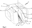
- Figure 4 shows the air filter 10 in an unassembled state without the mounting frame 32 (see Fig. 1-3 ) and the hood 20 (see Fig. 1-3 ). To better explain the illustration, the figure shows the partially sectioned area 38.
- the air filter 10 can be positioned as shown in Fig. 4 in a maintenance and/or assembly state. It can be provided that the second filter element 26 is in front of the first filter element 24 (see Fig. 1-3 ) or the mounting frame 32 is inserted into the filter housing 12. By such a sequential assembly of the filter elements 24, 26, the maintenance opening 18 can be kept small in its dimensions compared to simultaneous assembly.
- the second filter element 26 can be rotated into a fastening position by means of a hinge 68.
- the hinge 68 can, as shown in the figure, have a lever 70 arranged or formed on the frame 28 of the second filter element 26 and a rotation stop 72 arranged or formed on the filter housing 12, which in connection form a rotation axis 74 for the second filter element 26.
- the rotation stop 72 can be designed in the form of a plurality of rib-like projections, as shown.
- the second filter element 26 can then be rotated about the rotation axis 74 into the fastening position.
- the filter element 26 can be rotated out of the insertion area of the mounting frame 32 after insertion.
- the filter element 26 can then be held in the fastening position by means of a safety device 76 - here a snap hook. This can involve turning the second filter element 26 back into the insertion area of the mounting frame 32 (see Fig. 1 ) effectively prevent.
- the second filter element 26 can be pre-tensioned with the filter housing 12.
- the pre-tensioning promotes the circumferential contact of the second filter element 26 with the filter housing 12, so that particularly good tensioning is possible after the first filter element 24 has been inserted.
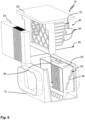
- Figure 5 shows a second embodiment of an air filter 10.
- the air filter 10 shown differs from the one shown in Fig. 1-4 shown embodiment by a modified design of the clamping wedge 40 and the wedge stop 50.
- the clamping wedge 40 has several - here three - clamping projections 48.
- the clamping projections 48 have a projection height 78 in the clamping direction 60, wherein the projection height 78 of adjacent clamping projections 48 decreases in the joining direction 36. In other words, the contact surface of the clamping wedge 40 is stepped.
- the partial stops 54 of the wedge stop 50 can also be designed in a stepped manner, as shown.
- the clamping projections 48 each come into contact with the stepped section of the contact surface 54 that is designed to be complementary to this clamping projection 48. This can ensure that, according to the key-lock principle, only filter elements 24, 26 that are matched to one another can be inserted together into the filter housing 12. Assembly errors can be prevented.
- FIG. 6 shows a third embodiment of the air filter 10 in an assembled state of the mounting frame 32 without the hood 20 (see Fig. 1 , 2 , 5 ).
- the air filter 10 shown has an inlet opening 14, an outlet opening 16 and a further outlet opening 79 in the filter housing 12.
- the outlet opening 16 is as shown in Fig. 6 covered by an air collection strip 80.
- the air collection strip 80 can fluidically connect the outlet opening 16 and the further outlet opening 79.
- the air collection strip 80 has a single air outlet 82. This can simplify the integration of the air filter 10 into an air duct (not shown).
- the further outlet opening 79 is preferably formed downstream of the first filter element 24 and upstream of the second filter element 26 on the filter housing 12. In other words, the second filter element 26 can be flowed around via the further outlet opening 79.
- the further outlet opening 79 preferably has a switchable bypass switching element 84 - here in the form of a bypass control flap. This allows the further outlet opening 79 to be opened and/or closed in a controlled manner. This enables controlled flow around the second filter element 26 if necessary.
- the clamping wedge 40 has the first wedge cheek 42 and the second wedge cheek 44.
- the wedge cheeks 42, 44 rest on corresponding contact surfaces 54 of the wedge stop 50.
- the wedge cheek 44 is designed to be fluid-permeable, here air-permeable, in order to improve the flow around the second filter element 26 when the bypass switching element 84 is open.
- the wedge cheek 44 protrudes further beyond the mounting frame 32 in the clamping direction 60 than the first wedge cheek 42. This enables the arrangement of the first filter element 24 in the filter housing 12 rotated about the joining direction 36. In other words, the first filter element 24 and the second filter element 26 are arranged at an angle to one another. This allows the dimensions of the mounting frame 32 and thus of the first filter element 24 to be increased. In addition, the flow cross-section between the first filter element 24 and the second filter element 26 can be increased, which simplifies the flow through the filter housing 12.
- the support area 58 on the filter housing 12 can be designed in a stepped manner.
- a key-lock principle can be provided on the support area 58 in a manner analogous to the clamping wedge 40 and the wedge stop 50.
- the mounting frame 32 can provide wedge counter-stops 56 adapted to the support area 58. This can increase the assembly security even further.
- Figure 7 shows a fourth embodiment of an air filter 10 in a sectional plan view.
- the first filter element 24, or the mounting frame 32, is arranged parallel to the second filter element 26 within the filter housing 12.
- the filter housing 12 has an inlet opening 14, an outlet opening 16 and a further outlet opening 79.
- the outlet opening 16 is formed on the outflow side 66 of the second filter element 26 in the filter housing 12.
- the further outlet opening 79 is - fluidically connected to the outflow side 66 of the first filter element 24 - formed between the first and the second filter element 24, 26 on the filter housing 12.
- the further outlet opening 79 has the bypass switching element 84.
- the bypass switching element 84 can be opened and air can be guided through the air filter housing 12 along the flow path 86 shown as an example. If the bypass switching element 84 is open, air that has been filtered through the first filter element 24 can flow around the second filter element 26 through the further outlet opening 79. As a result, the air filter 10 has a lower pressure loss, which has a positive effect on energy consumption.
Landscapes
- Chemical & Material Sciences (AREA)
- Chemical Kinetics & Catalysis (AREA)
- Engineering & Computer Science (AREA)
- Mechanical Engineering (AREA)
- Filtering Of Dispersed Particles In Gases (AREA)
Claims (19)
- Filtre à air (10) présentant- un boîtier de filtre (12) ayant une ouverture d'afflux (14) du côté air brut, une ouverture de sortie (16) du côté air pur et une ouverture de maintenance obturable (18);- un premier élément filtrant (24) et un second élément filtrant (26) disposés entre l'ouverture d'afflux (14) et l'ouverture de sortie (16) à l'intérieur du boîtier de filtre (12);- un cadre de montage (32) dans lequel est logé le premier élément filtrant (24);les éléments filtrants (24, 26) pouvant être traversés en série dans au moins un état opérationnel du filtre à air(10);le cadre de montage (32) pouvant être extrait du boîtier de filtre (12) dans une direction de jointure (36) à travers l'ouverture de maintenance (18) et inséré dans le boîtier de filtre (12) dans la direction de jointure (36);le cadre de montage (32) présentant une clavette de serrage (40) et le second élément filtrant (26) présentant une butée de clavette (50);la clavette de serrage (40) du cadre de montage (32) venant en appui par insertion sur la butée de clavette (50) du second élément filtrant (26) et le second élément filtrant (26) étant ainsi serré avec le boîtier de filtre (12) dans une direction de serrage (60) transversale à la direction de jointure (36).
- Filtre à air (10) selon la revendication 1, le cadre de montage (32) présentant, sur un côté opposé à la clavette de serrage (40), une contre-butée de clavette (56) qui s'appuie, à l'état monté sur le boîtier de filtre (12) dans un état de montage, de sorte qu'une force de serrage transmise au second élément filtrant (26) par l'intermédiaire de la clavette de serrage (40) peut être évacuée dans le boîtier de filtre (12).
- Filtre à air (10) selon la revendication 1 ou 2, la clavette de serrage (40) présentant au moins deux saillies de serrage (48) ayant une hauteur de saillie (78) différente dans la direction de serrage (60).
- Filtre à air (10) selon la revendication 3, la hauteur de saillie (78) des saillies de serrage (48) décroissant en direction de jointure (36) et la butée de clavette (50) présentant en direction de jointure (36) des sections étagées contre lesquelles repose respectivement une saillie de serrage (48).
- Filtre à air (10) selon l'une quelconque des revendications précédentes, la clavette de serrage (40) présentant au moins deux joues de clavette (42, 44), notamment les joues de clavette (42, 44) étant disposées sur des côtés opposés du cadre de montage (32).
- Filtre à air (10) selon la revendication 5, la butée de clavette (50) présentant deux butées partielles (54) localement espacées, notamment les butées partielles (54) étant disposées sur des côtés opposés du second élément filtrant (26).
- Filtre à air (10) selon l'une quelconque des revendications précédentes, la clavette de serrage (40) faisant saillie dans la direction de serrage (60) en dépassant le cadre de montage (32).
- Filtre à air (10) selon la revendication 7, au moins une joue de clavette (42, 44) de la clavette de serrage (40) étant réalisée perméable aux fluides.
- Filtre à air (10) selon la revendication 6 à 8, les joues de clavette (42, 44) dépassant à des distances différentes du cadre de montage (32) dans la direction de serrage (60), la joue de clavette (44) perméable aux fluides dépassant notamment davantage du cadre de montage (32) qu'une autre joue de clavette (42).
- Filtre à air (10) selon l'une quelconque des revendications précédentes, le premier élément filtrant (24) étant disposé de manière interchangeable sur le cadre de montage (32).
- Filtre à air (10) selon l'une quelconque des revendications précédentes, le cadre de montage (32) présentant une section de cadre entourant au moins partiellement de manière circonférentielle le premier élément filtrant (24) sur le bord, la clavette de serrage (40) étant notamment réalisée sur la section de cadre.
- Filtre à air (10) selon l'une quelconque des revendications précédentes, le premier élément filtrant (24) et le second élément filtrant (26) étant disposés dans le boîtier de filtre (12), à l'état monté, parallèlement l'un à l'autre ou selon un angle l'un à l'autre, notamment tourné selon un angle prédéterminé par rapport à la direction de jointure (36).
- Filtre à air (10) selon la revendication 12, le cadre de montage (32) étant disposé, à l'état monté, selon un angle par rapport au second élément filtrant (26) dans le boîtier de filtre (12), notamment tourné selon un angle prédéterminé par rapport à la direction de jointure (36).
- Filtre à air (10) selon l'une quelconque des revendications précédentes, l'ouverture de maintenance (18) pouvant être ouverte et fermée par un capot (20), le capot (20) étant disposé sur le cadre de montage (32).
- Filtre à air (10) selon l'une quelconque des revendications précédentes, le second élément filtrant (26) étant tourné dans une position de fixation au moyen d'une charnière (68) à l'intérieur du boîtier de filtre (12) et pouvant être fixé préalablement dans la position de fixation au moyen d'un dispositif de sécurité (76), notamment sous la forme d'un crochet d'encliquetage.
- Filtre à air (10) selon l'une quelconque des revendications précédentes, présentant un élément de commutation de dérivation commutable (84) qui se trouve en aval d'un élément filtrant (24) disposé en amont dans un sens d'écoulement, l'élément de commutation de dérivation (84) étant réalisé de manière à provoquer, dans un premier état opérationnel, un écoulement en série des deux éléments filtrants (24, 26) et, dans un second état opérationnel, un contournement au moins partiel de l'élément filtrant (26) disposé en aval.
- Filtre à air (10) selon la revendication 16 en combinaison avec la revendication 8, la joue de clavette (44), au moins au nombre d'une, du cadre de montage (32), réalisée de manière à être perméable aux fluides, fournit un trajet d'écoulement de dérivation entre les deux éléments filtrants (24, 26).
- Filtre à air (10) selon la revendication 16 ou 17, présentant une autre ouverture de sortie (79), l'autre ouverture de sortie (79) étant disposée sur le côté aval (66) du premier élément filtrant (24), et l'autre ouverture de sortie (79) pouvant être ouverte et fermée par l'élément de commutation de dérivation (84).
- Filtre à air (10) selon la revendication 18, présentant un guidage d'écoulement du côté de l'air pur, notamment sous la forme d'une barre collectrice d'air (80), qui relie fluidiquement les ouvertures de sortie (16, 79) du côté aval.
Applications Claiming Priority (1)
| Application Number | Priority Date | Filing Date | Title |
|---|---|---|---|
| DE102022119072.2A DE102022119072A1 (de) | 2022-07-29 | 2022-07-29 | Luftfilter |
Publications (2)
| Publication Number | Publication Date |
|---|---|
| EP4311590A1 EP4311590A1 (fr) | 2024-01-31 |
| EP4311590B1 true EP4311590B1 (fr) | 2024-10-23 |
Family
ID=86657199
Family Applications (1)
| Application Number | Title | Priority Date | Filing Date |
|---|---|---|---|
| EP23176673.4A Active EP4311590B1 (fr) | 2022-07-29 | 2023-06-01 | Filtre a air |
Country Status (6)
| Country | Link |
|---|---|
| US (1) | US12515156B2 (fr) |
| EP (1) | EP4311590B1 (fr) |
| KR (1) | KR20240016904A (fr) |
| CN (1) | CN117465202A (fr) |
| DE (1) | DE102022119072A1 (fr) |
| PL (1) | PL4311590T3 (fr) |
Families Citing this family (2)
| Publication number | Priority date | Publication date | Assignee | Title |
|---|---|---|---|---|
| DE102023206513A1 (de) * | 2023-07-10 | 2025-01-16 | Robert Bosch Gesellschaft mit beschränkter Haftung | Zellenvorrichtung, Verfahren zum Betreiben einer Zellenvorrichtung |
| DE102024131302A1 (de) * | 2024-10-28 | 2026-04-30 | Mann+Hummel Gmbh | Luftfilter mit gehäusefestem Stützgitter |
Family Cites Families (44)
| Publication number | Priority date | Publication date | Assignee | Title |
|---|---|---|---|---|
| DE2512724C3 (de) | 1975-03-22 | 1979-02-22 | Puralator Filter Gmbh, 7110 Oehringen | Ansaugluftfilter für Brennkraftmaschinen |
| JPS55164765A (en) | 1979-06-08 | 1980-12-22 | Yamaha Motor Co Ltd | Air cleaner device |
| JPS6067852U (ja) | 1983-10-19 | 1985-05-14 | 三菱重工業株式会社 | 研削盤の吸塵装置 |
| DE3911153A1 (de) | 1989-04-06 | 1990-10-11 | Mann & Hummel Filter | Ansaugluftfilter fuer brennkraftmaschinen |
| JPH04118125U (ja) | 1991-03-29 | 1992-10-22 | 株式会社土屋製作所 | 角型エアクリーナ |
| JP3225345B2 (ja) | 1995-08-29 | 2001-11-05 | 株式会社テネックス | フイルタ部材の取付装置 |
| JPH09234321A (ja) | 1996-02-29 | 1997-09-09 | Tenetsukusu:Kk | フイルタ部材の取付装置 |
| DE19638790A1 (de) | 1996-09-21 | 1998-03-26 | Mann & Hummel Filter | Luftfilter |
| US5740774A (en) | 1996-12-18 | 1998-04-21 | Siemens Electric Limited | Engine induction air system having improved air filter accessibility |
| JPH11132117A (ja) | 1997-08-26 | 1999-05-18 | Tokyo Roki Co Ltd | エアクリーナ |
| DE19741337A1 (de) | 1997-09-19 | 1999-03-25 | Mann & Hummel Filter | Luftansaugsystem |
| JP2001329921A (ja) | 2000-03-17 | 2001-11-30 | Toyo Roki Mfg Co Ltd | エアクリーナ |
| DE10026437A1 (de) | 2000-05-29 | 2001-12-06 | Mann & Hummel Filter | Filtereinrichtung |
| ES2279140T5 (es) * | 2002-05-09 | 2009-04-16 | Donaldson Company, Inc. | Filtro de aire con medio de filtro acanalado. |
| JP2004060600A (ja) | 2002-07-31 | 2004-02-26 | Toyo Roki Mfg Co Ltd | エアクリーナ |
| JP4302452B2 (ja) | 2003-07-18 | 2009-07-29 | 株式会社Roki | エアクリーナ |
| DE10347103A1 (de) * | 2003-10-10 | 2005-06-09 | Mann + Hummel Gmbh | Filtersystem |
| EP1722880B2 (fr) * | 2004-02-17 | 2018-10-03 | Donaldson Company, Inc. | Systemes de filtre a air, elements filtrants reutilisables, et methodes s'y rapportant |
| US7905936B2 (en) * | 2004-04-30 | 2011-03-15 | Donaldson Company, Inc. | Filter arrangements; housing; assemblies; and, methods |
| FR2896016B1 (fr) | 2006-01-10 | 2010-06-11 | Mann & Hummel Gmbh | Filtre a air pour vehicule automobile |
| DE202006011991U1 (de) | 2006-08-03 | 2007-12-06 | Mann + Hummel Gmbh | Luftfiltereinheit mit einem radial geteilten Gehäuse |
| FR2908159B1 (fr) | 2006-11-07 | 2009-01-23 | Mark Iv Systemes Moteurs Soc P | Dispositif de filtre a air a tiroir et ensemble d'admission comprenant un tel dispositif |
| US7597735B2 (en) | 2006-12-21 | 2009-10-06 | Cummins Filtration Ip Inc. | Apparatus and system for uniform sealing force in an air filter assembly |
| JP4697158B2 (ja) * | 2007-03-08 | 2011-06-08 | トヨタ紡織株式会社 | エアクリーナ |
| JP2008248848A (ja) | 2007-03-30 | 2008-10-16 | Denso Corp | 内燃機関のエアクリーナ |
| US8926724B2 (en) * | 2008-02-26 | 2015-01-06 | Mann + Hummel Gmbh | Filtering device, in particular air filter |
| US20150107200A1 (en) * | 2008-02-26 | 2015-04-23 | Mann+Hummel Gmbh | Filter Device, Especially Air Filter |
| US20140250843A1 (en) * | 2013-03-11 | 2014-09-11 | Baldwin Filters, Inc. | Side Entry Filter |
| DE102013020653A1 (de) * | 2013-12-05 | 2015-06-11 | Rt-Filtertechnik Gmbh | Filtervorrichtung, insbesondere in Form einer Luftfiltervorrichtung |
| DE112015002635T5 (de) * | 2014-06-03 | 2017-03-09 | Cummins Filtration Ip, Inc. | Filterbaugruppe mit Nockenschloss-Filter-Schnittstelle |
| DE102014012490A1 (de) * | 2014-08-27 | 2016-03-03 | Mann + Hummel Gmbh | Filterelement mit schräger Dichtungsebene |
| US11591993B2 (en) * | 2015-02-09 | 2023-02-28 | Mann+Hummel Gmbh | Filter element and air cleaner assembly |
| DE102016002037A1 (de) * | 2015-02-19 | 2016-08-25 | Mann + Hummel Gmbh | Filterelementverspannung mit elastischem Dämpfungselement |
| DE102015006713A1 (de) * | 2015-05-29 | 2016-03-31 | Mann + Hummel Gmbh | Verspannvorrichtung zur Verspannung eines Fluidfilterelementes, insbesondere Luftfilterelementes in einem Filtergehäuse und Fluidfilter |
| JP6582955B2 (ja) | 2015-12-14 | 2019-10-02 | トヨタ紡織株式会社 | エアクリーナ |
| DE102016001132A1 (de) * | 2016-02-03 | 2017-08-03 | Mann + Hummel Gmbh | Filterelement, Elementrahmen eines Filterelements, Filterbalg eines Filterelements, Filtergehäuse und Filter |
| DE102016001134A1 (de) * | 2016-02-03 | 2017-08-03 | Mann + Hummel Gmbh | Filtergehäuse und Filter |
| KR101766126B1 (ko) | 2016-03-14 | 2017-08-23 | 현대자동차주식회사 | 차량용 서랍식 에어클리너 |
| AU2018281331B2 (en) * | 2017-06-05 | 2023-08-24 | Donaldson Company, Inc. | Side-load air filter assemblies and methods of use |
| JP7268538B2 (ja) | 2019-08-28 | 2023-05-08 | トヨタ紡織株式会社 | エアクリーナ |
| JP2021065841A (ja) | 2019-10-24 | 2021-04-30 | トヨタ自動車株式会社 | エアクリーナ |
| DE102020107345A1 (de) * | 2020-03-17 | 2021-09-23 | Mann+Hummel Gmbh | Aerosolabscheider sowie Verfahren zum Einbau eines Koaleszenz-Filterelementes in einen Aerosolabscheider |
| US20220274041A1 (en) * | 2021-02-26 | 2022-09-01 | Parker-Hannifin Corporation | Side entry wave seal air cleaner |
| DE102022119073A1 (de) * | 2022-07-29 | 2024-02-01 | Mann+Hummel Gmbh | Filter sowie Spannkeil für einen Filter |
-
2022
- 2022-07-29 DE DE102022119072.2A patent/DE102022119072A1/de not_active Ceased
-
2023
- 2023-06-01 EP EP23176673.4A patent/EP4311590B1/fr active Active
- 2023-06-01 PL PL23176673.4T patent/PL4311590T3/pl unknown
- 2023-07-25 KR KR1020230096505A patent/KR20240016904A/ko active Pending
- 2023-07-28 CN CN202310945068.6A patent/CN117465202A/zh active Pending
- 2023-07-31 US US18/362,501 patent/US12515156B2/en active Active
Also Published As
| Publication number | Publication date |
|---|---|
| US20240033667A1 (en) | 2024-02-01 |
| EP4311590A1 (fr) | 2024-01-31 |
| US12515156B2 (en) | 2026-01-06 |
| KR20240016904A (ko) | 2024-02-06 |
| DE102022119072A1 (de) | 2024-02-01 |
| CN117465202A (zh) | 2024-01-30 |
| PL4311590T3 (pl) | 2025-03-10 |
Similar Documents
| Publication | Publication Date | Title |
|---|---|---|
| EP2675547B1 (fr) | Élément de filtre à air, carter de filtre à air et système de filtre à air | |
| EP2247364B1 (fr) | Élément filtrant à poignée | |
| EP4311590B1 (fr) | Filtre a air | |
| EP3017854B1 (fr) | Filtre destiné à filtrer un fluide | |
| EP1967247A1 (fr) | Filtre à air comprimé et adapteur adéquat | |
| DE102011089969B4 (de) | Abgasbehandlungsvorrichtung | |
| DE102014016300B4 (de) | Filter sowie Verwendung eines Hohlfilterelements in diesem Filter | |
| EP4311591A1 (fr) | Filtre et cale de serrage pour filtre | |
| EP2635363B1 (fr) | Filtre à air pour espace intérieur et ensemble filtre | |
| DE2623133A1 (de) | Filter zum trennen hoeherer dichte von material geringerer dichte | |
| WO2017133798A1 (fr) | Boîtier de filtre et filtre | |
| EP2178615B1 (fr) | Plateau filtrant | |
| EP1216743A1 (fr) | Systéme de filtre | |
| DE202010018248U1 (de) | Luftfilter eines Verbrennungsmotors | |
| DE102018213332A1 (de) | Filtereinrichtung, Filtereinsatz und Verfahren zum Wechseln eines Filtereinsatzes bei einer Filtereinrichtung | |
| DE10347103A1 (de) | Filtersystem | |
| WO2009052911A1 (fr) | Filtre d'habitacle destiné à un système de chauffage ou de climatisation de véhicule motorisé | |
| DE3240710A1 (de) | Entlueftungsschalldaempfer | |
| DE4442851C2 (de) | Vorrichtung zur Filterung eines Luftstromes, insbesondere für eine Heiz- bzw. Klimaanlage in einem Kraftfahrzeug | |
| DE102007048395A1 (de) | Innenraumfilter für eine Heizungs- oder Klimaanlage eines Kraftwagens | |
| DE202008001819U1 (de) | Filtereinrichtung, insbesondere Ansaugluftfilter für eine Brennkraftmaschine | |
| DE69213344T2 (de) | Ausgangdruckkontrollgerät | |
| EP4200053B1 (fr) | Élément filtrant et système de filtration | |
| DE202011052303U1 (de) | Kanalschwebstofffilter zur Filterung eines strömenden Gases | |
| DE10032384A1 (de) | Filtersystem für ein Kraftfahrzeug |
Legal Events
| Date | Code | Title | Description |
|---|---|---|---|
| PUAI | Public reference made under article 153(3) epc to a published international application that has entered the european phase |
Free format text: ORIGINAL CODE: 0009012 |
|
| STAA | Information on the status of an ep patent application or granted ep patent |
Free format text: STATUS: THE APPLICATION HAS BEEN PUBLISHED |
|
| AK | Designated contracting states |
Kind code of ref document: A1 Designated state(s): AL AT BE BG CH CY CZ DE DK EE ES FI FR GB GR HR HU IE IS IT LI LT LU LV MC ME MK MT NL NO PL PT RO RS SE SI SK SM TR |
|
| STAA | Information on the status of an ep patent application or granted ep patent |
Free format text: STATUS: REQUEST FOR EXAMINATION WAS MADE |
|
| 17P | Request for examination filed |
Effective date: 20240325 |
|
| RBV | Designated contracting states (corrected) |
Designated state(s): AL AT BE BG CH CY CZ DE DK EE ES FI FR GB GR HR HU IE IS IT LI LT LU LV MC ME MK MT NL NO PL PT RO RS SE SI SK SM TR |
|
| GRAP | Despatch of communication of intention to grant a patent |
Free format text: ORIGINAL CODE: EPIDOSNIGR1 |
|
| STAA | Information on the status of an ep patent application or granted ep patent |
Free format text: STATUS: GRANT OF PATENT IS INTENDED |
|
| INTG | Intention to grant announced |
Effective date: 20240527 |
|
| GRAS | Grant fee paid |
Free format text: ORIGINAL CODE: EPIDOSNIGR3 |
|
| GRAA | (expected) grant |
Free format text: ORIGINAL CODE: 0009210 |
|
| STAA | Information on the status of an ep patent application or granted ep patent |
Free format text: STATUS: THE PATENT HAS BEEN GRANTED |
|
| AK | Designated contracting states |
Kind code of ref document: B1 Designated state(s): AL AT BE BG CH CY CZ DE DK EE ES FI FR GB GR HR HU IE IS IT LI LT LU LV MC ME MK MT NL NO PL PT RO RS SE SI SK SM TR |
|
| REG | Reference to a national code |
Ref country code: GB Ref legal event code: FG4D Free format text: NOT ENGLISH |
|
| REG | Reference to a national code |
Ref country code: CH Ref legal event code: EP |
|
| REG | Reference to a national code |
Ref country code: DE Ref legal event code: R096 Ref document number: 502023000229 Country of ref document: DE |
|
| REG | Reference to a national code |
Ref country code: IE Ref legal event code: FG4D Free format text: LANGUAGE OF EP DOCUMENT: GERMAN |
|
| P01 | Opt-out of the competence of the unified patent court (upc) registered |
Free format text: CASE NUMBER: APP_63465/2024 Effective date: 20241129 |
|
| REG | Reference to a national code |
Ref country code: LT Ref legal event code: MG9D |
|
| REG | Reference to a national code |
Ref country code: NL Ref legal event code: MP Effective date: 20241023 |
|
| REG | Reference to a national code |
Ref country code: SK Ref legal event code: T3 Ref document number: E 45771 Country of ref document: SK |
|
| PG25 | Lapsed in a contracting state [announced via postgrant information from national office to epo] |
Ref country code: NL Free format text: LAPSE BECAUSE OF FAILURE TO SUBMIT A TRANSLATION OF THE DESCRIPTION OR TO PAY THE FEE WITHIN THE PRESCRIBED TIME-LIMIT Effective date: 20241023 |
|
| PG25 | Lapsed in a contracting state [announced via postgrant information from national office to epo] |
Ref country code: NL Free format text: LAPSE BECAUSE OF FAILURE TO SUBMIT A TRANSLATION OF THE DESCRIPTION OR TO PAY THE FEE WITHIN THE PRESCRIBED TIME-LIMIT Effective date: 20241023 |
|
| PG25 | Lapsed in a contracting state [announced via postgrant information from national office to epo] |
Ref country code: HR Free format text: LAPSE BECAUSE OF FAILURE TO SUBMIT A TRANSLATION OF THE DESCRIPTION OR TO PAY THE FEE WITHIN THE PRESCRIBED TIME-LIMIT Effective date: 20241023 Ref country code: IS Free format text: LAPSE BECAUSE OF FAILURE TO SUBMIT A TRANSLATION OF THE DESCRIPTION OR TO PAY THE FEE WITHIN THE PRESCRIBED TIME-LIMIT Effective date: 20250223 Ref country code: PT Free format text: LAPSE BECAUSE OF FAILURE TO SUBMIT A TRANSLATION OF THE DESCRIPTION OR TO PAY THE FEE WITHIN THE PRESCRIBED TIME-LIMIT Effective date: 20250224 |
|
| PG25 | Lapsed in a contracting state [announced via postgrant information from national office to epo] |
Ref country code: FI Free format text: LAPSE BECAUSE OF FAILURE TO SUBMIT A TRANSLATION OF THE DESCRIPTION OR TO PAY THE FEE WITHIN THE PRESCRIBED TIME-LIMIT Effective date: 20241023 |
|
| PG25 | Lapsed in a contracting state [announced via postgrant information from national office to epo] |
Ref country code: BG Free format text: LAPSE BECAUSE OF FAILURE TO SUBMIT A TRANSLATION OF THE DESCRIPTION OR TO PAY THE FEE WITHIN THE PRESCRIBED TIME-LIMIT Effective date: 20241023 |
|
| PG25 | Lapsed in a contracting state [announced via postgrant information from national office to epo] |
Ref country code: ES Free format text: LAPSE BECAUSE OF FAILURE TO SUBMIT A TRANSLATION OF THE DESCRIPTION OR TO PAY THE FEE WITHIN THE PRESCRIBED TIME-LIMIT Effective date: 20241023 |
|
| PG25 | Lapsed in a contracting state [announced via postgrant information from national office to epo] |
Ref country code: NO Free format text: LAPSE BECAUSE OF FAILURE TO SUBMIT A TRANSLATION OF THE DESCRIPTION OR TO PAY THE FEE WITHIN THE PRESCRIBED TIME-LIMIT Effective date: 20250123 |
|
| PG25 | Lapsed in a contracting state [announced via postgrant information from national office to epo] |
Ref country code: LV Free format text: LAPSE BECAUSE OF FAILURE TO SUBMIT A TRANSLATION OF THE DESCRIPTION OR TO PAY THE FEE WITHIN THE PRESCRIBED TIME-LIMIT Effective date: 20241023 Ref country code: GR Free format text: LAPSE BECAUSE OF FAILURE TO SUBMIT A TRANSLATION OF THE DESCRIPTION OR TO PAY THE FEE WITHIN THE PRESCRIBED TIME-LIMIT Effective date: 20250124 |
|
| PG25 | Lapsed in a contracting state [announced via postgrant information from national office to epo] |
Ref country code: RS Free format text: LAPSE BECAUSE OF FAILURE TO SUBMIT A TRANSLATION OF THE DESCRIPTION OR TO PAY THE FEE WITHIN THE PRESCRIBED TIME-LIMIT Effective date: 20250123 |
|
| PG25 | Lapsed in a contracting state [announced via postgrant information from national office to epo] |
Ref country code: SM Free format text: LAPSE BECAUSE OF FAILURE TO SUBMIT A TRANSLATION OF THE DESCRIPTION OR TO PAY THE FEE WITHIN THE PRESCRIBED TIME-LIMIT Effective date: 20241023 |
|
| PGFP | Annual fee paid to national office [announced via postgrant information from national office to epo] |
Ref country code: DE Payment date: 20250618 Year of fee payment: 3 Ref country code: PL Payment date: 20250522 Year of fee payment: 3 |
|
| PG25 | Lapsed in a contracting state [announced via postgrant information from national office to epo] |
Ref country code: DK Free format text: LAPSE BECAUSE OF FAILURE TO SUBMIT A TRANSLATION OF THE DESCRIPTION OR TO PAY THE FEE WITHIN THE PRESCRIBED TIME-LIMIT Effective date: 20241023 |
|
| PG25 | Lapsed in a contracting state [announced via postgrant information from national office to epo] |
Ref country code: EE Free format text: LAPSE BECAUSE OF FAILURE TO SUBMIT A TRANSLATION OF THE DESCRIPTION OR TO PAY THE FEE WITHIN THE PRESCRIBED TIME-LIMIT Effective date: 20241023 |
|
| PGFP | Annual fee paid to national office [announced via postgrant information from national office to epo] |
Ref country code: FR Payment date: 20250627 Year of fee payment: 3 |
|
| PGFP | Annual fee paid to national office [announced via postgrant information from national office to epo] |
Ref country code: AT Payment date: 20250721 Year of fee payment: 3 Ref country code: RO Payment date: 20250527 Year of fee payment: 3 |
|
| REG | Reference to a national code |
Ref country code: DE Ref legal event code: R097 Ref document number: 502023000229 Country of ref document: DE |
|
| PGFP | Annual fee paid to national office [announced via postgrant information from national office to epo] |
Ref country code: TR Payment date: 20250526 Year of fee payment: 3 Ref country code: SK Payment date: 20250527 Year of fee payment: 3 |
|
| PG25 | Lapsed in a contracting state [announced via postgrant information from national office to epo] |
Ref country code: CZ Free format text: LAPSE BECAUSE OF FAILURE TO SUBMIT A TRANSLATION OF THE DESCRIPTION OR TO PAY THE FEE WITHIN THE PRESCRIBED TIME-LIMIT Effective date: 20241023 |
|
| PLBE | No opposition filed within time limit |
Free format text: ORIGINAL CODE: 0009261 |
|
| STAA | Information on the status of an ep patent application or granted ep patent |
Free format text: STATUS: NO OPPOSITION FILED WITHIN TIME LIMIT |
|
| PG25 | Lapsed in a contracting state [announced via postgrant information from national office to epo] |
Ref country code: SE Free format text: LAPSE BECAUSE OF FAILURE TO SUBMIT A TRANSLATION OF THE DESCRIPTION OR TO PAY THE FEE WITHIN THE PRESCRIBED TIME-LIMIT Effective date: 20241023 |
|
| 26N | No opposition filed |
Effective date: 20250724 |
|
| PGFP | Annual fee paid to national office [announced via postgrant information from national office to epo] |
Ref country code: IT Payment date: 20250630 Year of fee payment: 3 |
|
| PG25 | Lapsed in a contracting state [announced via postgrant information from national office to epo] |
Ref country code: MC Free format text: LAPSE BECAUSE OF FAILURE TO SUBMIT A TRANSLATION OF THE DESCRIPTION OR TO PAY THE FEE WITHIN THE PRESCRIBED TIME-LIMIT Effective date: 20241023 |
|
| PG25 | Lapsed in a contracting state [announced via postgrant information from national office to epo] |
Ref country code: LU Free format text: LAPSE BECAUSE OF NON-PAYMENT OF DUE FEES Effective date: 20250601 |
|
| REG | Reference to a national code |
Ref country code: BE Ref legal event code: MM Effective date: 20250630 |
|
| PG25 | Lapsed in a contracting state [announced via postgrant information from national office to epo] |
Ref country code: IE Free format text: LAPSE BECAUSE OF NON-PAYMENT OF DUE FEES Effective date: 20250601 |
|
| PG25 | Lapsed in a contracting state [announced via postgrant information from national office to epo] |
Ref country code: BE Free format text: LAPSE BECAUSE OF NON-PAYMENT OF DUE FEES Effective date: 20250630 |