EP4311639A1 - Ensemble rasoir - Google Patents
Ensemble rasoir Download PDFInfo
- Publication number
- EP4311639A1 EP4311639A1 EP23187149.2A EP23187149A EP4311639A1 EP 4311639 A1 EP4311639 A1 EP 4311639A1 EP 23187149 A EP23187149 A EP 23187149A EP 4311639 A1 EP4311639 A1 EP 4311639A1
- Authority
- EP
- European Patent Office
- Prior art keywords
- razor
- handle
- connecting arm
- separation preventing
- preventing protrusion
- Prior art date
- Legal status (The legal status is an assumption and is not a legal conclusion. Google has not performed a legal analysis and makes no representation as to the accuracy of the status listed.)
- Granted
Links
Images









Classifications
-
- B—PERFORMING OPERATIONS; TRANSPORTING
- B26—HAND CUTTING TOOLS; CUTTING; SEVERING
- B26B—HAND-HELD CUTTING TOOLS NOT OTHERWISE PROVIDED FOR
- B26B21/00—Razors of the open or knife type; Safety razors or other shaving implements of the planing type; Hair-trimming devices involving a razor-blade; Equipment therefor
- B26B21/40—Details or accessories
- B26B21/52—Handles, e.g. tiltable, flexible
- B26B21/521—Connection details, e.g. connection to razor heads
-
- B—PERFORMING OPERATIONS; TRANSPORTING
- B26—HAND CUTTING TOOLS; CUTTING; SEVERING
- B26B—HAND-HELD CUTTING TOOLS NOT OTHERWISE PROVIDED FOR
- B26B21/00—Razors of the open or knife type; Safety razors or other shaving implements of the planing type; Hair-trimming devices involving a razor-blade; Equipment therefor
- B26B21/08—Razors of the open or knife type; Safety razors or other shaving implements of the planing type; Hair-trimming devices involving a razor-blade; Equipment therefor involving changeable blades
- B26B21/14—Safety razors with one or more blades arranged transversely to the handle
- B26B21/22—Safety razors with one or more blades arranged transversely to the handle involving several blades to be used simultaneously
- B26B21/222—Safety razors with one or more blades arranged transversely to the handle involving several blades to be used simultaneously with the blades moulded into, or attached to, a changeable unit
- B26B21/225—Safety razors with one or more blades arranged transversely to the handle involving several blades to be used simultaneously with the blades moulded into, or attached to, a changeable unit the changeable unit being resiliently mounted on the handle
Definitions
- the present disclosure relates to a razor assembly.
- a razor is a product for cutting facial or body hair such as beard and mustache.
- the razor is composed of a razor handle for gripping and a razor cartridge provided with a razor blade for shaving in contact the skin.
- the razor cartridge is pivotably coupled to the razor handle.
- the razor handle and the razor cartridge are configured in a modular in design, so that the user can replace either as needed.
- the razor handle and the razor cartridge may be unintentionally separated during use.
- the user should stop shaving and reattach the razor handle and the razor cartridge again in order to continue shaving. Also, in such separation situation, the user may sometimes mistakenly perceive the razor as damaged and end up discarding the razor handle or cartridge that can still function properly. In addition, an attempt to insert the cartridge forcibly into the handle may result in an injury caused by the razor blade of the cartridge.
- a guard is located at a lower end of the front side of the razor cartridge, the razor blade is located in the middle, and a lubricating band is located at an upper end.
- the guard contacts the user's skin prior to the razor blade, helping to pull the user's skin through a material such as rubber or open structure or pre-applying shaving aids to assist in shaving before the razor blade comes into contact with the skin.
- the lubricating band comprises a lubricating composition to reduce skin irritation and help smooth shaving.
- the lubricating band serves to apply the lubricating composition to the shaved skin following the razor blade.
- a cutting edge of the razor blade is generally directional and extends in a specific direction. Accordingly, the cutting edge performs shaving only when stroked in a specific direction (a correct shaving direction when properly installed). When the cutting edge is stroked in the opposite direction, shaving is not performed. That is, in general, the razor cartridge has a directional shape.
- the razor cartridge may be coupled in the opposite direction.
- the direction of the razor blade is reversed, so shaving becomes difficult, and the guard and/or lubrication band have difficulty performing their roles efficiently.
- An aspect of the present disclosure provides a razor assembly capable of preventing separation of a razor handle and a razor cartridge in a situation not intended by a user.
- Another aspect of the present disclosure provides a razor assembly capable of guiding correct assembly of a razor by allowing a cartridge to be properly attached to a razor handle in a correct direction while preventing the cartridge from being attached to the razor handle in the opposite direction.
- a razor assembly including: a razor cartridge including at least one razor blade; and a razor handle pivotably coupled to the razor cartridge.
- the razor cartridge may include: a blade housing accommodating the razor blade so that at least a portion of a cutting edge of the at least one razor blade is exposed toward a front side; and a handle coupling part provided on one side of the blade housing and pivotably coupled to the razor handle.
- the handle coupling part may comprise a separation preventing protrusion protruding to prevent the razor handle from being separated from the handle coupling part.
- the razor handle may include a connecting arm that moves along one surface of the handle coupling part.
- the connecting arm positions the separation preventing protrusion inside of an inner wall of the connecting arm while the connecting arm is moved along the one surface of the handle coupling part.
- the connecting arm may include an accommodating groove recessed from the inner wall to receive the separation preventing protrusion when the connecting arm is coupled to the handle coupling part.
- the handle coupling part may further include an arc-shaped support for guiding a pivoting motion of the razor handle, and the connecting arm may slide along one surface of the arc-shaped support.
- the separation preventing protrusion may protrude from the arc-shaped support, and an inner wall of the connecting arm may accommodate the separation preventing protrusion while the connecting arm slides along the one surface of the arc-shaped support part.
- the separation preventing protrusion may be spaced apart from a most protruding point of the arc-shaped support.
- the razor handle may be pivotably coupled to the razor cartridge between a neutral position and a pivot limit position, and when the razor handle is in the neutral position, at least a portion of the separation preventing protrusion may be positioned not to be aligned with the accommodating groove.
- the razor handle may be pivotably coupled to the razor cartridge between a neutral position and a pivot limit position, and when the razor handle is in the pivot limit position or between the neutral position and the pivot limit position, the separation preventing protrusion and the accommodating groove may be aligned with each other.
- the handle coupling part may further include a lateral support part that is spaced apart from the separation preventing protrusion and protrudes toward one side of the blade housing, and the connecting arm may be positioned between the lateral support part and the separation preventing protrusion.
- the connecting arm may be moved along the one surface of the handle coupling part in a state where one side of the connecting arm is supported by the separation preventing protrusion and the other side of the connecting arm is supported by the lateral support part.
- the lateral support part may further include a hook support part that supports the connecting arm toward a front side of the razor cartridge so that the connecting arm is prevented from being separated rearward of the razor cartridge.
- the separation preventing protrusion may be disposed eccentrically from a central portion of the razor cartridge and the accommodating groove is disposed eccentrically from a central portion of the connecting arm so as to prevent the razor cartridge from being reversely coupled to the razor handle.
- the second accommodating groove may be formed at a periphery of the inner wall of the inner wall of the connecting arm.
- the separation preventing protrusion may have an asymmetrical shape with respect to a direction in which the razor handle is coupled to the razor cartridge, so that the razor cartridge is prevented from being coupled to the razor handle in a reverse direction.
- the separation preventing protrusion may include: a first inclined surface protruding from one surface of the handle coupling part and having a predetermined angle relative to the one surface of the handle coupling part; and a second inclined surface protruding from the other surface of the handle coupling part and inclined in a direction toward the first inclined surface.
- a width between the first inclined surface and the second inclined surface may decrease as it goes in a protruding direction of the separation preventing protrusion.
- a length of the second inclined surface may be longer than a length of the first inclined surface.
- the accommodating groove may be recessed from the inner wall of the connecting arm, so that a space accommodating the separation preventing protrusion has a shape corresponding to a shape of the separation preventing protrusion.
- the razor handle may further include: a return force providing unit comprising an elastic material to elastically support the blade housing in a state in which the razor handle is coupled to the handle coupling part.
- a forward/backward direction is an up/down direction or a left/right direction depending on a point of view.
- a cutting edge mentioned in the following description may refer to a blade portion that is positioned at a front end of a razor blade to cut hair.
- FIGS. 1 to 3 schematic components of a razor assembly 1 according to an embodiment of the present disclosure will be described.
- FIG. 1 is a perspective view of a razor assembly according to one embodiment of the present disclosure.
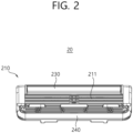
- FIG. 2 is a front view of a razor cartridge according to an embodiment of the present disclosure.
- FIG. 3 is an exploded perspective view of the razor assembly shown in FIG. 1 .
- the razor assembly 1 may include a razor handle 10 and a razor cartridge 20.
- the razor handle 10 may correspond to a handle to be held by a user while using the razor.
- the razor handle 10 may have an elongated shape so that the user can comfortably grip.
- the razor handle 10 may be pivotably coupled to the razor cartridge 20 so that an angle thereof can be adjusted to adapt to a curvature of the skin during shaving.
- the razor handle 10 may include subcomponents of a gripping handle 130, a return force providing part 120, and a connecting arm 110.
- the gripping handle 130 may be a part that occupies a large portion of the razor handle 10 and includes a portion to be gripped by a user with a hand. In order for the user to grip the gripping handle 130 easily, grooves formed to correspond to the shape of fingers or pads made of materials such as rubber may be provided in the gripping handle 130 to increase friction with the user's skin.
- the return force providing part 120 may extend from one end of the gripping handle 130 and may be formed of a material having elasticity. A free end of the return force providing part 120 may come into contact with a surface of the razor cartridge 20 while the razor handle 10 is coupled to the razor cartridge 20.
- the return force providing part 120 may provide a return force for maintaining the razor cartridge 20 at a predetermined angle relative to the razor handle 10 when there is no external force. To this end, the return force providing part 120 may elastically support the razor cartridge 20 while the razor handle 10 is coupled with the razor cartridge 20. In doing so, even if an external force is applied to the razor cartridge 20 and the razor cartridge 20 pivots with respect to the razor handle 10, the razor cartridge 20 may be able to return to an initial state when the external force is removed.
- the return force providing part 120 may be provided in an extended shape protruding from an end portion of the gripping handle 130. In addition, the return force providing part 120 may contact the razor cartridge 20 and extend along a curved path so that the return force providing part 120 bends upon an external force and straightens when the external force is removed.
- the return force providing part may be provided as a single return force providing part or may be provided as a plurality of return force providing part.
- the return force providing part 120 is not limited to the embodiment shown in the drawings, and may have various modified embodiments capable of providing a return force by contacting the razor cartridge 20.
- the return force providing part 120 may be implemented in a spring plunger method.
- the connecting arm 110 may have a structure coupled to the razor cartridge 20. While coupled to the razor cartridge 20, the connecting arm 110 may be movable along one surface of a handle coupling part 220 which will be described later.
- the connecting arm 110 may be provided as a pair of connecting arms having a symmetric shape, and the connecting arms may be provided on both sides of the return force providing part 120, respectively.
- the return force providing part 120 may be formed to extend from a central portion of one end of the grip handle 130, and the respective connecting arms 110 may be formed to extend from the left and right ends of the grip handle 130.
- the pair of connecting arms 110 may include a material having elasticity so that a width of the connecting arms 110 can be adjusted during the separation or coupling of the razor handle 10. More specifically, a user may couple the razor handle 10 and the razor cartridge 20 by positioning the connecting arm 110 behind the handle coupling part 220 and then having the connecting arm 110 enter into a space in the handle coupling part 220.
- the connecting arm 110 may be mounted in the inner space of the handle coupling part 220 by a force that the user applies in the direction of the handle coupling part 220. In this case, the connecting arm 110 may enter along an inclined surface of a hook support part 223b (see FIGS. 4 and 5 ) while entering into the hand coupling part 220.
- the pair of connecting arms 110 may gradually come closer to each other and a width therebetween may be decrease.
- the support by the hook support part 223b may be released, the pair of connecting arms 110 may be spaced apart from each other again, and the connecting arms 110 and the handle coupler 220 may be coupled.
- the razor cartridge 20 may be a cartridge that performs the cutting of hair, because the razor cartridge 20 includes at least one razor blade.
- the razor cartridge 20 may cut hair while moving on the skin in a direction in which the user operates the razor handle 10.
- the razor cartridge 20 may include a lubricating band 230, a guard 240, a blade housing 210, and a handle coupling part 220.
- a cutting edge positioned at a front end of a razor blade 211 may be exposed to the outside of the blade housing 210. Referring to FIG. 2 , the razor blade 211 moves downward and cuts the hair located on a movement path.
- the lubricating band 230 is disposed above the razor blade 211 on the front side of the blade housing 210, and may follow a point through which the razor blade 211 passes.
- the lubricating band 230 may be coated with a lubricating composition such as oil or medicine to reduce irritation of the skin, and accordingly, the lubricating band 230 may soothe the skin where the razor blade 211 passes.
- the guard 240 is disposed lower than the razor blade 211 on the front side of the blade housing 210, and may pass through a point where the razor blade 211 passes during shaving.
- the guard 240 may contact the user's skin prior to the razor blade 211 to pull the user's skin through a rubber material or open structure and/or to apply shaving aids to assist in shaving before the razor blade 211 touches the skin.
- the blade housing 210 accommodates a razor blade and may be a component forming the overall shape of the razor cartridge 20.
- the blade housing 210 may accommodate the razor blade 211 so that at least a portion of the cutting edge of the razor blade 211 for cutting hair is exposed to the front. In doing so, when the front side of the blade housing 210 is in close contact with the skin and moves along the skin, the cutting edge may cut hair from the skin.
- the handle coupling part 220 may be provided on one side of the blade housing 210, more specifically, on the rear side of the blade housing 210, and may have a structure that is pivotably coupled to the razor handle 10. A detailed configuration of the handle coupler 220 will be described with reference to FIGS. 4 to 5 .
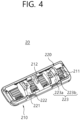
- FIG. 4 is a perspective view of the razor cartridge 20 according to an embodiment of the present disclosure.
- FIG. 5 is a bottom view of the razor cartridge 20 according to an embodiment of the present disclosure.
- a protruding support part 212 and a handle coupling part 220 may be provided at the rear of the blade housing 210. Also, the cutting edge of the razor blade 211 may not be exposed to the rear side of the blade housing 210.
- the protruding support part 212 may be a component that supports a free end of the return force providing part 120 in a state in which the razor cartridge 20 is coupled to the razor handle 10.
- the return force providing part 120 supported by the protruding support part 212 may be bent by an external force when the razor cartridge 20 pivots, and may be straighten again and push the protruding support part 212 when the external force is removed.
- the protruding support part 212 may be formed to protrude near an upper central portion of the rear side of the blade housing 210. In addition, the protruding support part 212 may be positioned rearward than the razor blade 211.
- a pair of handle coupling parts 220 may be symmetrically disposed on both sides of the protruding support part 212.
- components of the handle coupling part 220 will be described, and a direction toward the protruding support part 212 will be referred to as an inner side, and a direction away from the protruding support part 212 will be referred to as an outer side.
- the handle coupling part 220 may include an arc-shaped support part 221, a lateral support part 223, and a separation preventing protrusion 222.
- the arc-shaped support 221 may be a component that guides a pivoting motion of the connecting arm 110 (see FIGS. 1 and 2 ). More specifically, the arc-shaped support 221 may form a path where an end of the connecting arm 110 contracts and moves when the connecting arm 110 pivots.
- the arc-shaped support 221 may be provided as a convex arc-shaped member protruding toward the rear of the blade housing 210.
- a surface of the arc-shaped support 221 that directly contacts with the connecting arm 110 may have a curved surface corresponding to a curvature of an end portion of the connecting arm 110.
- the arc-shaped supports 221 may also be provided as a pair of supports and may be symmetrically positioned with respect to the protruding support part 212.
- the lateral support part 223 may be a component for supporting a lateral side of the connecting arm 110.
- the lateral support part 223 may be formed protruding toward the rear of the blade housing 210 and may be positioned outside the arc-shaped support part 221. In doing so, the lateral support part 223 may prevent the connecting arm 110 coupled to the razor cartridge 20 from being separated outward from the arc-shaped support part 221.
- the side support part 223 may include a side wall 223a and a hook support part 223b.
- the side wall 223a is a frame that protrudes from a side surface of the arc-shaped support part 221, and may prevent the connecting arm 110 from being separated outward from the arc-shaped support part 221.
- a distance d1 between a pair of side walls may correspond to a width w1 (see FIG. 7 ) of the connecting arm 110 when there is no external force.
- the hook support part 223b may be a member that prevents the connecting arm 110 from being separated backward from the razor cartridge 20. To this end, the hook support part 223b may support the connecting arm 110 pivoting at the rear of the arc-shaped support part 221 toward the front side.
- the hook support part 223b may be formed protruding inward from a free end of the side wall 223a and may have a surface facing the arc-shaped support part 221.
- the connecting arm 110 may perform an up/down pivoting movement between the hook support 223b and the arc-shaped support 221, being supported at the rear by the hook support 223b and at the front by the arc-shaped support 221.
- the separation preventing protrusion 222 may formed protruding from the blade housing 210 to prevent the connecting arm 110 from being separated from the handle coupling part 220.
- the separation preventing protrusion 222 may prevent the connecting arm 110 on the arc-shaped support part 221 from being separated in an inward direction of the arc-shaped support part 221.
- the separation preventing protrusion 222 may be located on the inside of the arc-shaped support 221 and may be provided as a pair of supports to correspond to the pair of connecting arms 110. However, the separation preventing protrusion 222 may not necessarily be provided as the pair of supports, and may be provided only on an inner side of any one arc-shaped support part 221. Hereinafter, for convenience of description, it will be described that the separation preventing protrusion 222 is provided as a pair of separation preventing protrusions, but the present disclosure is not limited thereto.
- the separation preventing protrusion 222 may be located at a position eccentrically away from the center of the blade housing 210.
- the separation preventing protrusion 222 may be formed protruding in the downward direction from the maximum protruding point of the arc-shaped support 221.
- the separation preventing protrusion 222 may be provided in an asymmetrical shape.
- the separation preventing protrusion 222 may have a substantially triangular shape. This will be described later with reference to FIGS. 19 to 20 .
- FIG. 6 is a detailed view of an end portion of a razor handle 10 according to an embodiment of the present disclosure.
- FIG. 7 is a detailed view of an end portion of the razor handle 10 according to an embodiment of the present disclosure, as viewed from a different angle than that of FIG. 6 .
- a separation preventing flange 111 formed to protrude outward from a front end of the connecting arm 110 may be positioned at a front end of the connecting arm 110.
- the separation preventing flange 111 may be positioned in a space between the arc-shaped support part 221 (see FIG. 4 ) and the hook support part 223b (see FIG. 4 ). Accordingly, in a state in which the razor handle 10 and the razor cartridge 20 are coupled, forward and backward movement of the separation preventing flange 111 may be restricted by the arc-shaped support part 221 and the hook support part 223b.
- the separation preventing flange 111 may be positioned between the separation preventing protrusion 222 (see FIG. 4 ) and the side wall 223a (see FIG. 4 ). Accordingly, in a state in which the razor handle 10 and the razor cartridge 20 are coupled, leftward and rightward movement of the separation preventing flange 111 may be restricted by the separation preventing protrusion 222 and the sidewall 223a.
- the width w1 of the pair of connecting arms 110 corresponds to the distance d1 between the pair of sidewalls 223a (see FIG. 5 ), and thus the pair of connecting arms 110 may be accommodated between the side walls 223a.
- the width w1 of the pair of connecting arms 110 may be the same as or slightly smaller than the distance d1 between the pair of sidewalls 223a.
- the width w1 between the pair of connecting arms 110 may be greater than a distance d2 between a pair of hook support parts 223b.
- the width of the separation preventing flange 111 may be greater than a protruding width d3 of the hook support parts 223b.
- a width of one connecting arm 110 may correspond to a distance between the lateral support part 223 and the separation preventing protrusion 222.
- An arc-shaped contact surface 114 having a curvature so as to be seated on the arc-shaped support 221 may be formed in a front surface of the separation preventing flange 111.
- the arc-shaped contact surface 114 may be formed with a concave curved surface to correspond to the shape of the convex arc-shaped support part 221.
- a central angle a1 of the arc-shaped contact surface 114 may be formed in consideration of a pivotable range of the connecting arm 110.
- a first stopper 112 and a second stopper 113 may be formed at both ends of the separation preventing flange 111.
- the first stopper 112 may protrude and be formed at one end of the separation preventing flange 111
- the second stopper 113 may protrude and be formed at the other end of the separation preventing flange 111. Since the first stopper 112 and the second stopper 113 protrude from the both ends of the arc-shaped contact surface 114, the connecting arm 110 may be able to pivot by the central angle a1 of the arc-shaped contact surface 114.
- a first accommodating groove 115 formed as a result of inward recession of the surface of the connecting arm 110, and a second accommodating groove 116 additionally recessed from the first accommodating groove 115 may be formed in an inner wall of the front end of the connecting arm 110.
- the first accommodating groove 115 and the second accommodating groove 116 may be provided as a pair and may be formed at positions symmetrical to those of the connecting arms 110.
- the first accommodating groove 115 may accommodate the separation preventing protrusion 222 when the connecting arm 110 pivots along the arc-shaped support 221 within a range of the central angle a1.
- a width w2 between the pair of first accommodating grooves 115 may be equal or similar to a distance between the pair of separation preventing protrusions 222 so that an inner wall of the first accommodating groove 115 and the separation preventing protrusion 222 does not interfere with the pivoting motion of the connecting arm 110.
- the second accommodating groove 116 may be a groove in which the separation preventing protrusion 222 is accommodated when the connecting arm 110 is coupled to or separated from the handle coupling part 220.
- the second accommodating groove 116 may be formed by being recessed near the periphery of the first accommodating groove 115.
- an inner space of the second accommodating groove 116 may have a shape identical or similar to a shape of the separation preventing protrusion 222.
- the second accommodating groove 116 may be formed at a position eccentrically away from a central axis of the connecting arm 110.
- a depth d4 of the second accommodating groove 116 may correspond to a width of the separation preventing protrusion 222.
- a user may have the pair of connecting arms 110 enter into a position between the hook support parts 223b to couple the connecting arms 110 and the handle coupling part 220.
- the user may pivot the connecting arm 110 so that the second accommodating groove 116 is positioned next to the separation preventing protrusion 222, and then the user may apply an eternal force to bring the connecting arms 110 closer to each other so that the separation preventing protrusion 222 can be accommodated in the second accommodating groove 116. Then, the user may separate the razor handle 10 and the razor cartridge 20 by separating the connecting arm 110 from the handle coupling part 220.
- the depth d4 of the second accommodating groove 116 may be equal to or greater than the protruding width d3 of the hook support part 223b. In doing so, when the connecting arm 110 moves inward by the depth d4 of the second accommodating groove 116, the separation preventing flange 111 may come outside of the hook support part 223b.
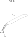
- FIG. 8 is a view showing a state in which the razor handle 10 according to an embodiment of the present disclosure is in a neutral position with respect to the razor cartridge 20.
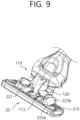
- FIG. 9 is a view showing a coupled state of the razor handle 10 and the razor cartridge 20 in the neutral position.
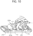
- FIG. 10 is a view showing a coupled state of the razor handle 10 and the razor cartridge 20 in the neutral position, as viewed from an angle different from that of FIG. 9 .
- the neutral position shown in FIG. 8 may be a position of the razor handle 10 relative to the razor cartridge 20 when there is no external force.
- the razor cartridge 20 may receive a counterclockwise force based on FIG. 8 due to an elastic force of the return force providing part 120.
- an angle between the razor cartridge 20 and the razor handle 10 may be minimized.
- the second stopper 113 may come into contact with the hook support part 223b by the elastic force of the return force providing part 120. Further pivoting of the second stopper 113 may be prevented due to interference by the hook support part 223b.
- the first stopper 112 may come into contact with the blade housing 210 by the elastic force of the return force providing part 120. Likewise, further pivoting of the first stopper 112 may be prevented due to interference with the blade housing 210.
- the second accommodating groove 116 and the separation preventing protrusion 222 may not be arranged in a straight line. Accordingly, in a case where in a state where the razor handle 10 is in the neutral position, even if there is an external force, the separation preventing protrusion 222 may not be accommodated in the second accommodating groove 116 but may be supported on the inner wall of the first accommodating groove 115.
- the separation preventing protrusion 222 it is possible to prevent the separation preventing protrusion 222 from being accommodated in the second accommodating groove 116 in the neutral position.
- the separation preventing flange 111 may be positioned between the hook support 223b, the arc-shaped support 221, the lateral support part 223, and the separation preventing protrusion 222, thereby preventing separation of the razor assembly 1.
- FIG. 11 is a view showing a state in which the razor handle 10 according to an embodiment of the present disclosure is in the pivot limit position with respect to the razor cartridge 20.
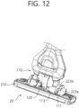
- FIG. 12 is a view showing a coupled state of the razor handle 10 and the razor cartridge 20 in the pivot limit position.
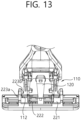
- FIG. 13 is a view showing a coupled state of the razor handle 10 and the razor cartridge 20 in the pivot limit position, as viewed from an angle different from that of FIG. 12 .
- the pivot limit position shown in FIG. 11 may be a position in a state where the razor handle 10 is maximally pivoted from the neutral position.
- a pivot angle a2 may indicate an angle between the neutral position and the pivot limit position.
- the razor handle 10 is pivotable between the neutral position and the pivot limit position with respect to the razor cartridge 20, and the pivotable range may be determined by an angle a1 (see FIG. 6 ) between the first stopper 112 and the second stopper 113.
- the pivot angle a2 of the razor handle 10 may be equal to the angle a1 between the first stopper 112 and the second stopper 113.
- the pivot limit position may be a position at which the razor handle 10 is maximally pivoted due to an external force, overcoming the elasticity of the resilience-providing portion 120.
- the second stopper 113 may come into contact with the blade housing 210.
- the separation preventing flange 111 may be restricted in movement between the hook support 223b and the arc-shaped support 221.
- the first stopper 112 in the pivot limit position, may be in contact with the hook support part 223b, thereby preventing upward pivoting.
- the first stopper 112 and/or the separation preventing flange 111 may be positioned between the side wall 223a and the separation preventing protrusion 222, thereby restricting lateral movement.
- the connecting arm 110 slides along a convex surface (rear surface) of the arc-shaped support 221 and may be able to move between the neutral position and the pivot limit position.
- the connecting arm 110 slides between the neutral position and the pivot limit position, the separation preventing protrusion 222 may be accommodated in the first accommodating groove 115 unless there is a special circumstance.
- the inner space of the first accommodating groove 115 may be formed of a size to accommodate a movement path of the separation preventing protrusion 222 that moves between the neutral position and the pivot limit position.
- FIG. 14 is a view showing a state in which the razor handle 20 according to an embodiment of the present disclosure is in a coupled position with respect to the razor cartridge 10.
- FIG. 15 is a view showing a coupled state of the razor handle 20 and the razor cartridge 10 in the coupled position.
- the razor handle 10 may form an angle a3 relative to the razor cartridge 20.
- An angle a3 between the razor handle 10 and the razor cartridge 20 in the coupled position may be smaller than the angle a2 in the pivot limit position.
- the angle a3 between the razor handle 10 and the razor cartridge 20 in the coupled position may be approximately 15 degrees.
- the separation preventing protrusion 222 and the second accommodating groove 116 may be positioned aligned with each other in the coupled position. In other words, the separation preventing protrusion 222 and the second accommodating groove 116 may be located on a straight line in the coupled position.
- the separation preventing protrusion 222 may be accommodated in the second accommodating groove 116 and the razor handle 10 may be separated from the razor cartridge 20.
- the user When assembling the razor handle 10 and the razor cartridge 20, the user places the razor handle 10 in the coupled position while applying an external force to the connecting arm 110, so that the razor handle 10 and the razor cartridge 20 can be coupled.
- the coupled position is between the neutral position and the pivot limit position, but the present disclosure is not limited thereto.
- the razor handle 10 may be able to be separated or coupled in the pivot limit position.
- FIG. 16 is a view conceptually showing the relative movement of the separation preventing protrusion 222 when the razor handle 10 pivots in a state where the razor handle 10 and the razor cartridge 20 are coupled together according to an embodiment of the present invention.
- the separation preventing protrusion 222 is shown as being moved, but this movement is a relative movement relative to the connecting arm 110.
- the razor cartridge 20 may be fixed and the razor handle 10 may be pivotable, or the razor handle 10 may be fixed and the razor cartridge 20 may be pivotable, or both of the razor cartridge 20 and the razor handle 10 may be pivotable relative to each other.
- the separation preventing protrusion 222 When the razor handle 10 is in the neutral position, the separation preventing protrusion 222 may be located at a highest point (which is the position indicated by a solid line) based on FIG. 16 . On the other hand, when the razor handle 10 is in the pivot limit position, the separation preventing protrusion 222 may be located at a lowest point (which is a position indicated by a dotted line) based on FIG. 16 .
- the separation preventing protrusion 222 may reciprocate within the first accommodating groove 115.
- one side of the connecting arm 110 may be supported by the lateral support part 223 and the other side thereof may be supported by the separation preventing protrusion 222. Due to this support, it is possible to effectively prevent separation of the razor cartridge 20 and the razor handle 10 even if a slight external force is applied to the connecting arm 110.
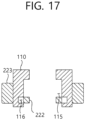
- FIG. 17 is a view conceptually showing the positional relationship between the separation preventing protrusion 222 and the second accommodating groove 116 in a state in which the razor handle 20 is in the coupled position according to an embodiment of the present disclosure.
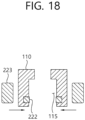
- FIG. 18 is a view conceptually showing a case where a distance between a pair of connecting arms 110 according to an embodiment of the present disclosure is reduced by an external force.
- the second accommodating groove 116 and the separation preventing protrusion 222 may be positioned aligned with each other.
- the shape and size of the second accommodating groove 116 correspond to the shape and size of the separation preventing protrusion 222, so the second accommodating groove 116 and the separation preventing protrusion 222 may be positioned not to be aligned or positioned to be misaligned each other in a situation other than FIG. 17 .
- the razor assembly it may be easy to couple and separate the razor handle 10 and the razor cartridge 20 only when the razor handle 10 has a specific angle relative to the razor cartridge 20. That is, since the coupling and separation of the razor handle 10 and the razor cartridge 20 are easy only in a certain state, the coupling and separation may be difficult in other states.
- a user may change the razor handle 10 to the state shown in FIG. 18 by applying an external force from the outside to the inside of each connecting arm 110.
- the separation preventing protrusion 222 may be accommodated into the second accommodating groove 116, and the connecting arm 110 may be separated from the razor cartridge 20.
- the coupling of the razor handle 10 and the razor cartridge 20 is performed in the reverse order of FIGS. 17 and 18 , so a description thereof will be omitted.
- FIG. 19 is a view showing a state when the razor cartridge 10 is coupled to the connecting arm 110 in a correct direction according to an embodiment of the present disclosure.
- FIG. 20 is a view showing a case where the razor cartridge 10 is positioned in the reverse direction to the connecting arm 110 according to an embodiment of the present disclosure.
- the separation preventing protrusion 222 may protrude at a position eccentric to one side from the center of the arc-shaped support 221 and may have an asymmetrical shape. More specifically, the separation preventing protrusion 222 may include a first inclined surface 222a and a second inclined surface 222b.
- the first inclined surface 222a may protrude and extend from the arc-shaped support 221, and may be a surface having a predetermined angle relative to the arc-shaped support 221.
- the first inclined surface 222a may have an angle substantially parallel to a coupling direction AA.
- the coupling direction AA may refer to a direction in which the razor handle 10 is coupled to the razor cartridge 20.
- an angle between the coupling direction AA and the razor cartridge 20 may be equal to an angle of the razor handle 10 relative to the razor cartridge 20 in the engagement position.
- first inclined surface 222a Due to this shape of the first inclined surface 222a, when the user presses the connecting arm 110 in the coupled position in the coupling direction AA, an inner wall of the second accommodating groove 116 may be guided along the first inclined surface 222a and an end portion of the connecting arm 110 may be accommodated inside the handle coupling part 220.
- the second inclined surface 222b may protrude and extend from the arc-shaped support part 221, and may have a slope that approaches the first inclined surface 222a. Since the second inclined surface 222b is inclined in a direction toward the first inclined surface 222a, a width of the separation preventing protrusion 222 may gradually become narrower along a protruding direction. That is, the separation preventing protrusion 222 may have a pointed shape in which a width decreases toward a free end.
- a length of the second inclined surface 222b may be longer than that of the first inclined surface 222a. Due to the difference in length and gradient between the first inclined surface 222a and the second inclined surface 222b, the separation preventing protrusion 222 may, when viewed from the side, have a shape similar to a right-angled triangle with a height defined by the first inclined surface 222a and a hypotenuse defined by the second inclined surface 222b.
- the inner wall of the second accommodating groove 116 may come into contact with the inclined surface 222b and be then guided and moved by the second inclined surface 222b. Therefore, even in this case, correct coupling between the razor handle 10 and the handle coupler 220 may be guided.
- the effect of the coupling guide by the second inclined surface 222b may be further maximized as the length of the second inclined surface 222b is longer.
- the length of the second inclined surface 222b may be set to an appropriate length so that the coupling is not allowed in most positions other than when the razor handle 10 is only slightly displaced from the coupled position.
- the guide effect by the first inclined surface 222a and the second inclined surface 222b may be further maximized.
- the coupled connecting arm 110 may be always misaligned with the separation preventing protrusion 222 and the second accommodating groove 116 in any position other than the coupled position. This misalignment prevents the separation preventing protrusion 222 from being accommodated into the second accommodating groove 116 even when an external force is applied, thereby preventing separation of the connecting arm 110.
- the separation preventing protrusion 222 is eccentrically positioned from a most protruding point of the arc-shaped support 221, so when the razor cartridge 20 is positioned in the reverse direction, the separation preventing protrusion 222 may be positioned at the front (in a downward direction in FIG. 20 ) of the body of the first accommodating groove 115 and/or the connecting arm 110.
- the separation preventing protrusion 222 may collide with the body of the connecting arm 110. This is because the separation preventing protrusion 222 and the second accommodation groove 116 have an asymmetrical shape, so when the separation preventing protrusion 222 and the second accommodation groove 116 are coupled in the reverse direction, the separation preventing protrusion 222 cannot be completely accommodated in the second accommodating groove 116.
- the arc-shaped support part 221 has a convex curved surface and the connecting arm 110 has a concave shape, but the present disclosure is not limited thereto.
- the arc-shaped support 221 may have a concave curved surface and the connecting arm 110 may have a convex shape.
Landscapes
- Life Sciences & Earth Sciences (AREA)
- Forests & Forestry (AREA)
- Engineering & Computer Science (AREA)
- Mechanical Engineering (AREA)
- Packaging Of Annular Or Rod-Shaped Articles, Wearing Apparel, Cassettes, Or The Like (AREA)
Applications Claiming Priority (2)
| Application Number | Priority Date | Filing Date | Title |
|---|---|---|---|
| KR20220091934 | 2022-07-25 | ||
| KR1020230064471A KR102897320B1 (ko) | 2022-07-25 | 2023-05-18 | 면도기 조립체 |
Publications (2)
| Publication Number | Publication Date |
|---|---|
| EP4311639A1 true EP4311639A1 (fr) | 2024-01-31 |
| EP4311639B1 EP4311639B1 (fr) | 2025-12-24 |
Family
ID=87429367
Family Applications (1)
| Application Number | Title | Priority Date | Filing Date |
|---|---|---|---|
| EP23187149.2A Active EP4311639B1 (fr) | 2022-07-25 | 2023-07-24 | Ensemble rasoir |
Country Status (3)
| Country | Link |
|---|---|
| US (1) | US12600051B2 (fr) |
| EP (1) | EP4311639B1 (fr) |
| ES (1) | ES3063548T3 (fr) |
Families Citing this family (1)
| Publication number | Priority date | Publication date | Assignee | Title |
|---|---|---|---|---|
| US12600051B2 (en) * | 2022-07-25 | 2026-04-14 | Dorco Co., Ltd. | Razor assembly |
Citations (2)
| Publication number | Priority date | Publication date | Assignee | Title |
|---|---|---|---|---|
| US5636442A (en) * | 1992-10-08 | 1997-06-10 | The Gillette Company | Shaving systems with blade holder |
| US20210178618A1 (en) * | 2016-06-24 | 2021-06-17 | Dorco Co., Ltd. | Razor |
Family Cites Families (6)
| Publication number | Priority date | Publication date | Assignee | Title |
|---|---|---|---|---|
| US4492024A (en) * | 1982-09-17 | 1985-01-08 | The Gillette Company | Razor blade assembly |
| MX2012001397A (es) | 2009-07-31 | 2012-03-26 | Bic Violex Sa | Maquina de afeitar en humedo. |
| KR101730415B1 (ko) * | 2016-06-24 | 2017-04-26 | 주식회사 도루코 | 관통홀이 형성된 핸들을 포함하는 면도기 |
| US11298842B2 (en) * | 2018-09-05 | 2022-04-12 | The Gillette Company Llc | Razor structure |
| KR102892997B1 (ko) * | 2021-11-30 | 2025-12-03 | 주식회사 도루코 | 면도기 카트리지 |
| US12600051B2 (en) * | 2022-07-25 | 2026-04-14 | Dorco Co., Ltd. | Razor assembly |
-
2023
- 2023-07-21 US US18/356,575 patent/US12600051B2/en active Active
- 2023-07-24 ES ES23187149T patent/ES3063548T3/es active Active
- 2023-07-24 EP EP23187149.2A patent/EP4311639B1/fr active Active
Patent Citations (2)
| Publication number | Priority date | Publication date | Assignee | Title |
|---|---|---|---|---|
| US5636442A (en) * | 1992-10-08 | 1997-06-10 | The Gillette Company | Shaving systems with blade holder |
| US20210178618A1 (en) * | 2016-06-24 | 2021-06-17 | Dorco Co., Ltd. | Razor |
Also Published As
| Publication number | Publication date |
|---|---|
| ES3063548T3 (en) | 2026-04-17 |
| US12600051B2 (en) | 2026-04-14 |
| US20240025067A1 (en) | 2024-01-25 |
| EP4311639B1 (fr) | 2025-12-24 |
Similar Documents
| Publication | Publication Date | Title |
|---|---|---|
| US20230092827A1 (en) | Handle assembly and cartridge, and razor including same | |
| EP2078593B1 (fr) | Rasoir | |
| CN101790444B (zh) | 具有刀片单元偏置构件的剃刀 | |
| CN110430978B (zh) | 用于固持可围绕两个轴线枢转的刀头的剃刮手柄系统 | |
| CA2737995C (fr) | Poignees de rasoir destinees a etre reliees de maniere liberable a des cartouches de rasage et rasoirs comprenant de telles poignees | |
| EP0903205B1 (fr) | Rasoirs avec support de tête de rasoir pivotant et rotatif | |
| US8984756B2 (en) | Shaving system | |
| EP3565690B1 (fr) | Connecteur pour cartouche de rasoir | |
| EP0885697A1 (fr) | Rasoir avec tête de support de rasoir pivotante et rotative | |
| EP2177328A1 (fr) | Ensemble rasoir | |
| MX2010011155A (es) | Mango de afeitadora para un cartucho de afeitar retractil y una afeitadora que comprende un mango de afeitadora de este tipo. | |
| US10576648B2 (en) | Shaver handle with a lock and release mechanism for engaging and disengaging a razor cartridge | |
| EP4691712A1 (fr) | Manche de rasoir | |
| JPH037193A (ja) | レザー機構 | |
| CN101842199A (zh) | 包括剃刀手柄的剃刮系统 | |
| EP4311639A1 (fr) | Ensemble rasoir | |
| KR102897320B1 (ko) | 면도기 조립체 | |
| US20250170738A1 (en) | Razor cartridge | |
| EP3888861B1 (fr) | Mécanisme de couplage | |
| EP4706920A1 (fr) | Manche de rasoir | |
| EP4563306A1 (fr) | Cartouche de rasoir | |
| EP4511198B1 (fr) | Ensemble de montage | |
| WO2022152486A1 (fr) | Têtes de rasoir, kits, rasoirs et procédés les comprenant |
Legal Events
| Date | Code | Title | Description |
|---|---|---|---|
| PUAI | Public reference made under article 153(3) epc to a published international application that has entered the european phase |
Free format text: ORIGINAL CODE: 0009012 |
|
| STAA | Information on the status of an ep patent application or granted ep patent |
Free format text: STATUS: REQUEST FOR EXAMINATION WAS MADE |
|
| 17P | Request for examination filed |
Effective date: 20230724 |
|
| AK | Designated contracting states |
Kind code of ref document: A1 Designated state(s): AL AT BE BG CH CY CZ DE DK EE ES FI FR GB GR HR HU IE IS IT LI LT LU LV MC ME MK MT NL NO PL PT RO RS SE SI SK SM TR |
|
| RBV | Designated contracting states (corrected) |
Designated state(s): AL AT BE BG CH CY CZ DE DK EE ES FI FR GB GR HR HU IE IS IT LI LT LU LV MC ME MK MT NL NO PL PT RO RS SE SI SK SM TR |
|
| GRAP | Despatch of communication of intention to grant a patent |
Free format text: ORIGINAL CODE: EPIDOSNIGR1 |
|
| STAA | Information on the status of an ep patent application or granted ep patent |
Free format text: STATUS: GRANT OF PATENT IS INTENDED |
|
| INTG | Intention to grant announced |
Effective date: 20250725 |
|
| P01 | Opt-out of the competence of the unified patent court (upc) registered |
Free format text: CASE NUMBER: UPC_APP_8207_4311639/2025 Effective date: 20250929 |
|
| GRAS | Grant fee paid |
Free format text: ORIGINAL CODE: EPIDOSNIGR3 |
|
| GRAA | (expected) grant |
Free format text: ORIGINAL CODE: 0009210 |
|
| STAA | Information on the status of an ep patent application or granted ep patent |
Free format text: STATUS: THE PATENT HAS BEEN GRANTED |
|
| AK | Designated contracting states |
Kind code of ref document: B1 Designated state(s): AL AT BE BG CH CY CZ DE DK EE ES FI FR GB GR HR HU IE IS IT LI LT LU LV MC ME MK MT NL NO PL PT RO RS SE SI SK SM TR |
|
| REG | Reference to a national code |
Ref country code: CH Ref legal event code: F10 Free format text: ST27 STATUS EVENT CODE: U-0-0-F10-F00 (AS PROVIDED BY THE NATIONAL OFFICE) Effective date: 20251224 Ref country code: GB Ref legal event code: FG4D |
|
| REG | Reference to a national code |
Ref country code: DE Ref legal event code: R096 Ref document number: 602023010024 Country of ref document: DE |
|
| REG | Reference to a national code |
Ref country code: LT Ref legal event code: MG9D |
|
| PG25 | Lapsed in a contracting state [announced via postgrant information from national office to epo] |
Ref country code: NO Free format text: LAPSE BECAUSE OF FAILURE TO SUBMIT A TRANSLATION OF THE DESCRIPTION OR TO PAY THE FEE WITHIN THE PRESCRIBED TIME-LIMIT Effective date: 20260324 |
|
| PG25 | Lapsed in a contracting state [announced via postgrant information from national office to epo] |
Ref country code: FI Free format text: LAPSE BECAUSE OF FAILURE TO SUBMIT A TRANSLATION OF THE DESCRIPTION OR TO PAY THE FEE WITHIN THE PRESCRIBED TIME-LIMIT Effective date: 20251224 Ref country code: HR Free format text: LAPSE BECAUSE OF FAILURE TO SUBMIT A TRANSLATION OF THE DESCRIPTION OR TO PAY THE FEE WITHIN THE PRESCRIBED TIME-LIMIT Effective date: 20251224 |
|
| PG25 | Lapsed in a contracting state [announced via postgrant information from national office to epo] |
Ref country code: RS Free format text: LAPSE BECAUSE OF FAILURE TO SUBMIT A TRANSLATION OF THE DESCRIPTION OR TO PAY THE FEE WITHIN THE PRESCRIBED TIME-LIMIT Effective date: 20260324 |
|
| REG | Reference to a national code |
Ref country code: ES Ref legal event code: FG2A Ref document number: 3063548 Country of ref document: ES Kind code of ref document: T3 Effective date: 20260417 |
|
| PG25 | Lapsed in a contracting state [announced via postgrant information from national office to epo] |
Ref country code: LV Free format text: LAPSE BECAUSE OF FAILURE TO SUBMIT A TRANSLATION OF THE DESCRIPTION OR TO PAY THE FEE WITHIN THE PRESCRIBED TIME-LIMIT Effective date: 20251224 |