EP4311746A1 - Support pour l'ancrage d'un garde-boue sur un véhicule - Google Patents
Support pour l'ancrage d'un garde-boue sur un véhicule Download PDFInfo
- Publication number
- EP4311746A1 EP4311746A1 EP23159862.4A EP23159862A EP4311746A1 EP 4311746 A1 EP4311746 A1 EP 4311746A1 EP 23159862 A EP23159862 A EP 23159862A EP 4311746 A1 EP4311746 A1 EP 4311746A1
- Authority
- EP
- European Patent Office
- Prior art keywords
- support
- flange
- tube
- chassis
- axial seat
- Prior art date
- Legal status (The legal status is an assumption and is not a legal conclusion. Google has not performed a legal analysis and makes no representation as to the accuracy of the status listed.)
- Pending
Links
- 238000004873 anchoring Methods 0.000 title claims abstract description 11
- 238000013016 damping Methods 0.000 claims description 4
- 238000000034 method Methods 0.000 description 12
- 230000008569 process Effects 0.000 description 12
- 238000003466 welding Methods 0.000 description 12
- 239000000463 material Substances 0.000 description 6
- 239000002184 metal Substances 0.000 description 3
- 229910052751 metal Inorganic materials 0.000 description 3
- 241000531123 GB virus C Species 0.000 description 2
- 230000008901 benefit Effects 0.000 description 2
- 238000001962 electrophoresis Methods 0.000 description 2
- 230000000670 limiting effect Effects 0.000 description 2
- 150000002739 metals Chemical class 0.000 description 2
- 238000010422 painting Methods 0.000 description 2
- 230000003252 repetitive effect Effects 0.000 description 2
- 238000011282 treatment Methods 0.000 description 2
- CWYNVVGOOAEACU-UHFFFAOYSA-N Fe2+ Chemical compound [Fe+2] CWYNVVGOOAEACU-UHFFFAOYSA-N 0.000 description 1
- 238000010521 absorption reaction Methods 0.000 description 1
- 238000001311 chemical methods and process Methods 0.000 description 1
- 239000002131 composite material Substances 0.000 description 1
- 238000010276 construction Methods 0.000 description 1
- 230000008878 coupling Effects 0.000 description 1
- 238000010168 coupling process Methods 0.000 description 1
- 238000005859 coupling reaction Methods 0.000 description 1
- 230000001066 destructive effect Effects 0.000 description 1
- 230000000694 effects Effects 0.000 description 1
- 230000001788 irregular Effects 0.000 description 1
- 238000004519 manufacturing process Methods 0.000 description 1
- 238000010297 mechanical methods and process Methods 0.000 description 1
- 230000005226 mechanical processes and functions Effects 0.000 description 1
- 238000012986 modification Methods 0.000 description 1
- 230000004048 modification Effects 0.000 description 1
- 230000000750 progressive effect Effects 0.000 description 1
- 238000012797 qualification Methods 0.000 description 1
- 239000007921 spray Substances 0.000 description 1
- 239000000126 substance Substances 0.000 description 1
- 230000007704 transition Effects 0.000 description 1
Images


Classifications
-
- B—PERFORMING OPERATIONS; TRANSPORTING
- B62—LAND VEHICLES FOR TRAVELLING OTHERWISE THAN ON RAILS
- B62D—MOTOR VEHICLES; TRAILERS
- B62D25/00—Superstructure or monocoque structure sub-units; Parts or details thereof not otherwise provided for
- B62D25/08—Front or rear portions
- B62D25/16—Mud-guards or wings; Wheel cover panels
- B62D25/163—Mounting devices
- B62D25/166—Mounting devices by rods or other distance-keeping devices
-
- B—PERFORMING OPERATIONS; TRANSPORTING
- B62—LAND VEHICLES FOR TRAVELLING OTHERWISE THAN ON RAILS
- B62D—MOTOR VEHICLES; TRAILERS
- B62D25/00—Superstructure or monocoque structure sub-units; Parts or details thereof not otherwise provided for
- B62D25/08—Front or rear portions
- B62D25/16—Mud-guards or wings; Wheel cover panels
- B62D25/168—Mud guards for utility vehicles
Definitions
- the present invention relates to a support for anchoring a mudguard to a vehicle, in particular for trucks or semi-trailer trucks or articulated vehicles or double HGVs or trailers or semitrailers.
- the trailer is made up of a structure, the principal components of which are beams or profiles or longitudinal members, below which are fixed the axles that carry the wheels, and above which are fixed the superstructures that constitute the specific load configuration (compartment, refrigerated compartment, deck, tank and the like).
- These longitudinal members are used as a fixing base for supports, which we will refer to as tubes or flanged tubes, which are thus used for fixing the mudguard by way of adapted means, for example of the type illustrated in WO2021/073784 , in the name of this same Applicant.
- Conventional mudguards are usually constituted by a single body, made of metal or of plastic material, with a curved shape of approximately 180 degrees that surrounds the upper surface of the wheels of the vehicle, with which further elements are later associated such as for example splash guards and/or elements that perform spray protection functions and elements for fixing to the vehicle.
- the coupling between said tubes and the chassis of the vehicle is usually achieved by way of affixing elements such as bolts, nuts and washers.
- the welding process is a process that is considered "dirty" for the production environment and for the product obtained, plus it is difficult to qualify, and non-destructive qualification processes are burdensome.
- the welding process is also rather unstable and repetitive in terms of quality of the joint.
- the welding process further requires that the masses to be joined have a similar thermal inertia, which often, between a tube of adequate thickness and a flange that is turned or forged, is difficult to protect.
- the welding process also leaves working residues on the welded join which need to be cleaned or removed through chemical and/or mechanical processes that are burdensome and often not environmentally friendly.
- the aim of the present invention is therefore to resolve the above-mentioned technical problems, eliminating the drawbacks in the cited known art and therefore devising a support that makes it possible to obtain, rapidly and easily and in an environmentally-friendly manner, the anchoring of a mudguard to a vehicle.
- an object of the invention is to provide a support that makes it possible to obtain such anchoring repetitively and that offers structural stability in the absence of tensioning points and consequent fragility which could be the cause of possible breakages.
- Another object of the invention is to provide a support that presents a surface that is uncontaminated and therefore ready to receive surface finish treatments like galvanization, painting, or cataphoresis.
- Another object is to provide a support that, in addition to the foregoing characteristics, also combines that of being extremely resistant, of low weight and adequate to the workload to which it is subjected.
- Another object is to provide a support that can be provided with materials that have different characteristics in order to increase the hold on the mudguard, and the fixing to the chassis of the vehicle.
- Another object is to provide a support that is structurally simple and is low-cost.
- a support for anchoring a mudguard to a chassis of a vehicle characterized in that it is constituted by a tube at a first end of which a taper with a frustum shape structure is obtained, within which, by cold-deforming, a complementarily-shaped flange is kept captive, said flange comprising means configured for interconnection with said chassis of said vehicle.
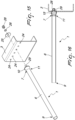
- the reference numeral 1 generally designates a support for anchoring a mudguard 2 to a chassis 3 of a vehicle (not shown), in particular for trucks or semi-trailer trucks or articulated vehicles or double HGVs or trailers or semitrailers.
- the mudguard 2 has an approximately C-shaped curved shape structure, and lies substantially on a circular arc; it has, on the external surface 4 facing away from the tire, means 5, for example of the type illustrated in WO2021/073784 in the name of this same Applicant, adapted to fix the anchoring support 1 to the mudguard 2.
- Such support is constituted by a tube 6, advantageously entirely hollow and of desired thickness, preferably circular in cross-section.
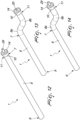
- the tube 6 can have a linear extension, as shown in Figures 1 to 6 , 12 , 15 and 16 , in which there are a first end 7 and a second, free end 9.
- the tube has a taper 10, obtained preferably by cold-deforming, which is frustum-shaped with a first minor base 11 blended with the tube 6 and the first major base 12 facing away and in the direction of the chassis 3 to which the tube 6 is to be coupled.
- the major base 12 has the terminal end 13 upset, for example cold-upset, so as to assume an L shape with an end lip 14 arranged on a plane that is substantially perpendicular to the longitudinal axis of the tube 6.
- the end lip 14 only partially overlaps the diameter of the major base 12 of the taper 10, preferably so as to occupy a space substantially equal to the diameter of the minor base 11.
- a complementarily-shaped flange 15 is placed within the taper 10, the flange being frustum-shaped with an annular ridge 16, protruding from the second minor base 17 of the flange 15, of an outside diameter approximately equal to the inside diameter of the tube 6.
- the tube 6 can be variously shaped; for example in Figures 13 and 14 the tube 6 has, starting from the first end 7, two curves 8a and 8b, mutually opposite and mutually sequential, so that the taper 10 which can be associated with the chassis 3 ends up being arranged, when installed, at a point different from the point of arrangement of the second, free end 9 of the tube 6.
- An annular perimetric seat 19 is provided at the second major base 18 of the flange 15, for part of its thickness, at which the complementarily-shaped end lip 14 of the terminal end 13 of the taper 10 is cold-upset.
- a first axial seat 20 is provided axially to the flange 15 and communicates, at the second minor base 17 of the flange 15, with a second axial seat 21 which is provided at the annular ridge 16.
- the second axial seat 21 has a larger diameter than the first axial seat 20.
- the first axial seat 20 and the second axial seat 21 combine to define means for interconnecting the tube 6 with the chassis 3 of the vehicle.
- first axial seat 20 can be internally threaded for interconnection with a complementarily-threaded first shank 22 of a bolt 23 that passes through one of a plurality of holes 24 which are provided in desired points on the chassis 3, as shown in Figure 2 .
- a first washer 25 and a second, vibration-damping washer 26 can be arranged on the first shank 22 and interposed between the chassis 3 and the head 27 of the bolt 23.
- a nut 28 can be stably positioned within the second axial seat 21, and the threaded first shank 22 be screwed therein.
- the head 27 of a bolt 23 can be stably positioned within the second axial seat 21, the shank of the bolt passing through the first axial seat 20 and protruding, axially to the flange 15, from the second major base 18.
- an externally-threaded second shank 29 can be obtained on the flange 15, the second shank protruding axially to the flange 15 from the second major base 18.
- the second shank 29 is then caused to pass through one of the plurality of holes 24 provided in desired points on the chassis 3 and then coupled to a complementarily-threaded nut 28 with the interposition of a first washer 25 and of a second, vibration-damping washer 26.
- the tube 6 will be inserted through or associated with the means 5 associated with the mudguard 2, which are constituted for example by adapted collars designed to envelop and clamp the tube 6.
- the geometry of the support can be developed on progressive transitions, with the absence of tensioning points and consequent fragility which could be the cause of possible breakage.
- the surface of the support is furthermore not contaminated by a welding operation and therefore ready to receive surface finish treatments like galvanization, painting, or cataphoresis.
- the flange that constitutes the support offers high strength which ensures an optimal connection to the chassis of the vehicle.
- the structure that constitutes the support furthermore makes it possible to use tubes of reduced thickness, more commensurate to the workload in that they are not constrained by weldability parameters.
- a support is obtained which is also aesthetically improved and which can be provided in solutions that entail the use of a round flange, with female threading or with male threading, or a square flange, or a triangular flange.
Landscapes
- Engineering & Computer Science (AREA)
- Chemical & Material Sciences (AREA)
- Combustion & Propulsion (AREA)
- Transportation (AREA)
- Mechanical Engineering (AREA)
- Body Structure For Vehicles (AREA)
Applications Claiming Priority (1)
| Application Number | Priority Date | Filing Date | Title |
|---|---|---|---|
| IT202022000003108U IT202200003108U1 (it) | 2022-07-25 | 2022-07-25 | Supporto di ancoraggio di un parafango ad un veicolo. |
Publications (1)
| Publication Number | Publication Date |
|---|---|
| EP4311746A1 true EP4311746A1 (fr) | 2024-01-31 |
Family
ID=89434227
Family Applications (1)
| Application Number | Title | Priority Date | Filing Date |
|---|---|---|---|
| EP23159862.4A Pending EP4311746A1 (fr) | 2022-07-25 | 2023-03-03 | Support pour l'ancrage d'un garde-boue sur un véhicule |
Country Status (2)
| Country | Link |
|---|---|
| EP (1) | EP4311746A1 (fr) |
| IT (1) | IT202200003108U1 (fr) |
Citations (6)
| Publication number | Priority date | Publication date | Assignee | Title |
|---|---|---|---|---|
| DE9318925U1 (de) * | 1993-11-09 | 1994-02-10 | BÄWA Bätzold & Wagner GmbH & Co KG, 42477 Radevormwald | Halterohranschluß zur Befestigung von Zusatzteilen an LKW und deren Anhänger |
| DE19546753A1 (de) * | 1994-12-30 | 1996-07-04 | Scania Cv Ab | Halterung zum Befestigen eines Kotflügels oder dergleichen an einem Fahrzeug |
| DE19831368A1 (de) * | 1998-07-13 | 2000-01-20 | Man Nutzfahrzeuge Ag | Vorrichtung zum Einspannen eines Halterohres für Nutzfahrzeuge |
| DE102005052645A1 (de) * | 2005-11-04 | 2007-05-10 | Man Nutzfahrzeuge Ag | Vorrichtung und Verfahren zum Befestigen eines Anbauteils an einem Rahmenteil eines Fahrzeugs |
| CN105172902A (zh) * | 2014-06-03 | 2015-12-23 | 常州良旭车辆配件有限公司 | 重型卡车后轮挡泥板支架及加工方法 |
| WO2021073784A1 (fr) | 2019-10-18 | 2021-04-22 | Lago Accessori S.R.L. | Dispositif d'ancrage à un tube associé à un véhicule et à un pare-chocs pouvant être associé au véhicule |
-
2022
- 2022-07-25 IT IT202022000003108U patent/IT202200003108U1/it unknown
-
2023
- 2023-03-03 EP EP23159862.4A patent/EP4311746A1/fr active Pending
Patent Citations (6)
| Publication number | Priority date | Publication date | Assignee | Title |
|---|---|---|---|---|
| DE9318925U1 (de) * | 1993-11-09 | 1994-02-10 | BÄWA Bätzold & Wagner GmbH & Co KG, 42477 Radevormwald | Halterohranschluß zur Befestigung von Zusatzteilen an LKW und deren Anhänger |
| DE19546753A1 (de) * | 1994-12-30 | 1996-07-04 | Scania Cv Ab | Halterung zum Befestigen eines Kotflügels oder dergleichen an einem Fahrzeug |
| DE19831368A1 (de) * | 1998-07-13 | 2000-01-20 | Man Nutzfahrzeuge Ag | Vorrichtung zum Einspannen eines Halterohres für Nutzfahrzeuge |
| DE102005052645A1 (de) * | 2005-11-04 | 2007-05-10 | Man Nutzfahrzeuge Ag | Vorrichtung und Verfahren zum Befestigen eines Anbauteils an einem Rahmenteil eines Fahrzeugs |
| CN105172902A (zh) * | 2014-06-03 | 2015-12-23 | 常州良旭车辆配件有限公司 | 重型卡车后轮挡泥板支架及加工方法 |
| WO2021073784A1 (fr) | 2019-10-18 | 2021-04-22 | Lago Accessori S.R.L. | Dispositif d'ancrage à un tube associé à un véhicule et à un pare-chocs pouvant être associé au véhicule |
Also Published As
| Publication number | Publication date |
|---|---|
| IT202200003108U1 (it) | 2024-01-25 |
Similar Documents
| Publication | Publication Date | Title |
|---|---|---|
| US7758060B2 (en) | Integrated tow hook and bumper mounting bracket | |
| US9108678B2 (en) | Vehicle support frames with interlocking features for joining members of dissimilar materials | |
| JP3520458B2 (ja) | ナックルブラケット | |
| US8657368B2 (en) | Hydroformed side pillar to lower back joint structure | |
| US7328909B2 (en) | Tower connecting bar structure | |
| US8590950B2 (en) | Vehicle bumper assembly with a removably coupled tie-down receiver | |
| US4944523A (en) | End link for stabilizer bar | |
| US20090108634A1 (en) | Clam shell bracket connecting automotive structural members | |
| US8146931B2 (en) | Wheel assembly | |
| EP3184410A1 (fr) | Structure de support de bras oscillant pour moto | |
| US6402179B1 (en) | Lightweight towing cross member for a vehicle | |
| US6533230B2 (en) | One-piece mounting bracket and vehicle damper assembly and mounting method | |
| EP2421743B1 (fr) | Dispositif pour fixer un etai a un chassis de vehicule et vehicule comprenant le dispositif | |
| WO2015000463A2 (fr) | Réservoir et procédé de production d'un réservoir | |
| JPH0214706Y2 (fr) | ||
| US20080001378A1 (en) | Built-up wheel control arm | |
| US6820882B2 (en) | Vehicle rear body structure | |
| IT202200003108U1 (it) | Supporto di ancoraggio di un parafango ad un veicolo. | |
| JP2002308149A (ja) | 車両用ストラットタワーバー | |
| JP2001012308A (ja) | 燃料ボンベ付自動車の燃料ボンベ搭載構造 | |
| CN208664849U (zh) | 海运拖钩结构、水箱下横梁以及汽车 | |
| KR102205193B1 (ko) | Nvh 및 r&h 향상을 위한 차량용 언더바 및 그 제조 방법 | |
| JPH0532384Y2 (fr) | ||
| KR20210067572A (ko) | 부품 마운팅 유닛 | |
| JPH053681U (ja) | 車両用懸架装置 |
Legal Events
| Date | Code | Title | Description |
|---|---|---|---|
| PUAI | Public reference made under article 153(3) epc to a published international application that has entered the european phase |
Free format text: ORIGINAL CODE: 0009012 |
|
| STAA | Information on the status of an ep patent application or granted ep patent |
Free format text: STATUS: THE APPLICATION HAS BEEN PUBLISHED |
|
| AK | Designated contracting states |
Kind code of ref document: A1 Designated state(s): AL AT BE BG CH CY CZ DE DK EE ES FI FR GB GR HR HU IE IS IT LI LT LU LV MC ME MK MT NL NO PL PT RO RS SE SI SK SM TR |
|
| STAA | Information on the status of an ep patent application or granted ep patent |
Free format text: STATUS: REQUEST FOR EXAMINATION WAS MADE |
|
| 17P | Request for examination filed |
Effective date: 20240305 |
|
| RBV | Designated contracting states (corrected) |
Designated state(s): AL AT BE BG CH CY CZ DE DK EE ES FI FR GB GR HR HU IE IS IT LI LT LU LV MC ME MK MT NL NO PL PT RO RS SE SI SK SM TR |