EP4312872B1 - Omnidirektionales mehrteiliges abutmentsystem für schraubenbefestigte zahnprothesen - Google Patents
Omnidirektionales mehrteiliges abutmentsystem für schraubenbefestigte zahnprothesen Download PDFInfo
- Publication number
- EP4312872B1 EP4312872B1 EP22816962.9A EP22816962A EP4312872B1 EP 4312872 B1 EP4312872 B1 EP 4312872B1 EP 22816962 A EP22816962 A EP 22816962A EP 4312872 B1 EP4312872 B1 EP 4312872B1
- Authority
- EP
- European Patent Office
- Prior art keywords
- abutment
- base
- screw
- lock screw
- swivel
- Prior art date
- Legal status (The legal status is an assumption and is not a legal conclusion. Google has not performed a legal analysis and makes no representation as to the accuracy of the status listed.)
- Active
Links
Images


Classifications
-
- A—HUMAN NECESSITIES
- A61—MEDICAL OR VETERINARY SCIENCE; HYGIENE
- A61C—DENTISTRY; APPARATUS OR METHODS FOR ORAL OR DENTAL HYGIENE
- A61C8/00—Means to be fixed to the jaw-bone for consolidating natural teeth or for fixing dental prostheses thereon; Dental implants; Implanting tools
- A61C8/0048—Connecting the upper structure to the implant, e.g. bridging bars
- A61C8/005—Connecting devices for joining an upper structure with an implant member, e.g. spacers
- A61C8/0062—Catch or snap type connection
-
- A—HUMAN NECESSITIES
- A61—MEDICAL OR VETERINARY SCIENCE; HYGIENE
- A61C—DENTISTRY; APPARATUS OR METHODS FOR ORAL OR DENTAL HYGIENE
- A61C13/00—Dental prostheses; Making same
- A61C13/01—Palates or other bases or supports for the artificial teeth; Making same
- A61C13/02—Palates or other bases or supports for the artificial teeth; Making same made by galvanoplastic methods or by plating; Surface treatment; Enamelling; Perfuming; Making antiseptic
-
- A—HUMAN NECESSITIES
- A61—MEDICAL OR VETERINARY SCIENCE; HYGIENE
- A61C—DENTISTRY; APPARATUS OR METHODS FOR ORAL OR DENTAL HYGIENE
- A61C8/00—Means to be fixed to the jaw-bone for consolidating natural teeth or for fixing dental prostheses thereon; Dental implants; Implanting tools
- A61C8/0018—Means to be fixed to the jaw-bone for consolidating natural teeth or for fixing dental prostheses thereon; Dental implants; Implanting tools characterised by the shape
- A61C8/0022—Self-screwing
-
- A—HUMAN NECESSITIES
- A61—MEDICAL OR VETERINARY SCIENCE; HYGIENE
- A61C—DENTISTRY; APPARATUS OR METHODS FOR ORAL OR DENTAL HYGIENE
- A61C8/00—Means to be fixed to the jaw-bone for consolidating natural teeth or for fixing dental prostheses thereon; Dental implants; Implanting tools
- A61C8/0048—Connecting the upper structure to the implant, e.g. bridging bars
- A61C8/005—Connecting devices for joining an upper structure with an implant member, e.g. spacers
- A61C8/0053—Connecting devices for joining an upper structure with an implant member, e.g. spacers with angular adjustment means, e.g. ball and socket joint
-
- A—HUMAN NECESSITIES
- A61—MEDICAL OR VETERINARY SCIENCE; HYGIENE
- A61C—DENTISTRY; APPARATUS OR METHODS FOR ORAL OR DENTAL HYGIENE
- A61C8/00—Means to be fixed to the jaw-bone for consolidating natural teeth or for fixing dental prostheses thereon; Dental implants; Implanting tools
- A61C8/0048—Connecting the upper structure to the implant, e.g. bridging bars
- A61C8/005—Connecting devices for joining an upper structure with an implant member, e.g. spacers
- A61C8/0066—Connecting devices for joining an upper structure with an implant member, e.g. spacers with positioning means
-
- A—HUMAN NECESSITIES
- A61—MEDICAL OR VETERINARY SCIENCE; HYGIENE
- A61C—DENTISTRY; APPARATUS OR METHODS FOR ORAL OR DENTAL HYGIENE
- A61C8/00—Means to be fixed to the jaw-bone for consolidating natural teeth or for fixing dental prostheses thereon; Dental implants; Implanting tools
- A61C8/0048—Connecting the upper structure to the implant, e.g. bridging bars
- A61C8/005—Connecting devices for joining an upper structure with an implant member, e.g. spacers
- A61C8/0068—Connecting devices for joining an upper structure with an implant member, e.g. spacers with an additional screw
-
- A—HUMAN NECESSITIES
- A61—MEDICAL OR VETERINARY SCIENCE; HYGIENE
- A61C—DENTISTRY; APPARATUS OR METHODS FOR ORAL OR DENTAL HYGIENE
- A61C8/00—Means to be fixed to the jaw-bone for consolidating natural teeth or for fixing dental prostheses thereon; Dental implants; Implanting tools
- A61C8/0048—Connecting the upper structure to the implant, e.g. bridging bars
- A61C8/0075—Implant heads specially designed for receiving an upper structure
Definitions
- the Ti base and abutment surfaces preferably include features to remove rotational symmetry about the azimuthal axis in the mating of the abutment and coping surfaces.
- Rotational locking features may also be included in these single mount systems.
- this rotational fixation is not generally required. For example, 30 degree tapered mating surfaces for multiple interface locations are sufficient to provide complete registration. This form is illustrated in the drawings of this disclosure for convenience, but is not meant to be limiting.
- the goal for all implant attached prostheses is to have a passive fit of the prosthesis superstructure to the implants to avoid stress on the prosthesis or on the osseointegration process of the implants. These stresses may cause problems during the initial loading or crop up much later. Misfit can lead to both mechanical and biological problems in single implant and multiple implant treatments.
- the mechanical problems may include loosening of prosthesis retaining and abutment screws and fracture of components including screws. Biological issues may include discomfort, progressive marginal bone loss, bacterial infection, microbial plaque buildup and implant loosening.
- a treatment option for edentulous patients that is gaining popularity involves the placement of four to eight implants in the edentulous jaw and the mounting of a prothesis arch.
- a transmucosal abutment is fastened to the implant and intended to remain in place indefinitely. While it would be desirable to have the axes of all of the implants located parallel to one another, underlying bone structure often results in installing implants at an angle from this ideal mutual orientation.
- "Multi-unit abutment" is a popular descriptor for a specific type of transmucosal abutment used for the restoration of the edentulous jaw with a single prosthesis, that is a full arch prosthesis.
- the multi-unit abutment (commonly referred to as an "MUA") is a fairly easy way to improve divergent angulations of implants with options of 0 degree, 17 degrees, and 30 degrees angulation corrections.
- 0 degree MUAs are easier to position because the abutment is positioned in line with the linear axis of the implant.
- the 17 and 30 degree MUAs typically include a "screw access" indicator that is relatively long and difficult to work around in tight spaces, such as the posterior of the jaw where these abutments are commonly positioned to compensate for the disto-angulation of the posterior implants popularized by Dr Paolo Maolo in 2004.
- An example of the complexity of the inventory management is when the implant system offers multiple implant/abutment connections (e.g., narrow platform and regular platform) and multiple heights to the MUAs (e.g., 1.5 mm, 2.5 mm, 3.5 mm, 4.5 mm, etc.) as well as different angulations or tilt angles (e.g., 0 degree, 17 degrees, and 30 degrees).
- implant/abutment connections e.g., narrow platform and regular platform
- multiple heights to the MUAs e.g., 1.5 mm, 2.5 mm, 3.5 mm, 4.5 mm, etc.
- different angulations or tilt angles e.g., 0 degree, 17 degrees, and 30 degrees.
- This inventory problem is increased when multi-unit abutment systems also require unique implants, Ti bases and prosthetic fasteners. This inventory management complexity is further exacerbated when practitioners prefer different vendor systems under different patient circumstances, or when different practitioners in a practice prefer different vendor offerings.
- Some commercial systems require the sequential assembly of the multi-unit abutment elements in situ during their installation in the patient's mouth. This increases the chance of the patient accidentally swallowing components. Some systems require multiple tools to be employed which can also extend procedure complexity and times.
- new multi-unit abutment embodiments are disclosed herein. These units are designated as omnidirectional in the sense of being able to be positioned over a continuous range of orientations sufficient for correcting implant angulation differences typically found in general practice. Although the discussion above was based on structural reasons, angled implants may also be preferred simply for aesthetic reasons, for example, to reorient screw access holes in single tooth crowns.
- Embodiments of omnidirectional multi-unit abutments are offered that have advantages in inventory management, placement procedures, options for angulation correction and flexibility, improving passive fit and to remove limitations to angle corrections or other issues with existing multi-unit abutment systems for single implant crowns and multiple implant prostheses.
- US 4,842,518 discloses a submergible screw-type implant including a longitudinal channel which directs bone chips towards the base of a bore in the patient's bone in which the implant is installed. These bone chips promote autogenous rapid regrowth of new bone to securely anchor the implant in place.
- angled abutments for supporting an artificial tooth structure or angularly adjustable abutments are provided.
- the angularly adjustable abutments may be in the form of a ball and socket joint in which the socket includes an inner casing having a peripheral extension that acts to lock the joint at the desired angle.
- the support for an artificial tooth may include a shock-absorbing cushion to prevent some of the forces of mastication from disturbing the implant.
- AT 375 012 discloses a dental jaw implant with a base part implanted in the bone substance of the human jaw.
- the invention is defined by the independent claim. Preferred embodiments of the invention are defined by the dependent claims.
- the invention relates to a multi-unit abutment for screw attachment to a dental implant which allows seating of Ti bases at a user-selected rotation and tilt angle relative to the implant.
- This seating orientation can be fixed prior to bonding the Ti base to the prosthesis, and in some embodiments can be adjusted or tightened by removing the prothesis retention screw while the Ti base is otherwise held onto the abutment.
- the final relative orientation of the adjustable abutment can be directly influenced by the fixed position of the Ti bases in the prosthesis. This can correct or reduce misalignments resulting from the accumulation of positioning errors in steps of the fabrication of the prosthesis relative to the initial position of the abutments.
- a dental prosthesis is defined broadly to be anything that incorporates one or more dental copings or Ti bases that can be mounted and removed from one or more implant abutments.
- Different Ti base designs are known in the dental industry, and the systems and methods disclosed here can be adapted to work with many commercially available types of Ti bases including pick-up copings, temporary cylinders, inserts and impression copings.
- Implant abutments are known in the dental industry having compatible interfaces to these Ti bases. Since the mechanical interface is the same, for the purposes of this disclosure, implant abutment is considered a generic term that includes abutment analogs.
- Abutment alignment systems and process methods with Ti bases and implants that are installed in a patient's jaw should be considered to also describe equivalent inventive concepts that may be used with Ti bases and implant analogs in a dental lab.
- a common geometry comprises a conical Ti base seated to a conical implant abutment.
- the inventive concepts disclosed herein can be used with different types of dental prostheses.
- the dental prosthesis can be any form of impression used in a dental lab to assist in creating and testing dental prostheses.
- a dental prosthesis can also be one fabricated in the dental lab using a physical model made from the impression, a dental prosthesis newly fabricated, or an existing prosthesis being converted for screw attachment.
- a dental prosthesis is defined to include a single-tooth appliance such as a crown, or any multiple-tooth bridge or denture. These prostheses may incorporate Ti bases to provide a separable interface to provide orientation with an appropriate abutment attached to a patient's jaw or gingiva.
- multi-unit abutments may also be used individually to provide mounting to an implant for single tooth prostheses.
- the term multi-unit abutment will be used herein whether for single implant or multiple implant applications and for any form of dental prosthesis.
- the multi-unit abutments for use with the inventive concepts disclosed herein include screw threads to mount the prosthesis with Ti bases onto the abutments and the abutments into the implants. While the concepts describe the typical male threads in the multi-unit abutment mating with female threads on the implant, this is for convenience in disclosure.
- inventive concepts may be applied with systems having female threads in the multi-unit abutment engaging a screw with male threads in an implant. These are considered to be straightforward variations of the inventive concepts.
- One benefit of preferring the typical female threading of the implant for abutment attachment is standardization and implementation flexibility.
- prosthetic screws with male threads and commercially available Ti bases are preferred, but may not be required to gain some benefit from inventive concepts disclosed. These types of variations are considered to be within the scope of this disclosure.
- proximal portions are nearer to the clinician than distal portions. While a term such as top is the opposite of the term bottom, and proximal is the opposite of distal, their actual relative orientation will be determined by the context of their use.
- tissue-side is used interchangeably with intaglio to indicate the side of a prosthesis that is opposite the occlusal or cameo surface.
- inventive systems disclosed are beneficially applicable to screw-attached prostheses and abutments. Key benefits of screw-attachment are variable tightening torques and reversibility.
- the terms permanent, semi-permanent, definitive and final when referring to screw-attachment are used interchangeably in this disclosure.
- a conventional screw that is definitively attached can still be removed by accessing the screw and rotating it in the opposite direction that was used for attachment.
- the attachment is semi-permanent, permanent or definitive in the sense that frequent attachment and removal is not anticipated for normal use.
- a temporary screw attachment is applied for a planned process duration or other anticipated interval.
- the positioning of the Ti bases in the dental prosthesis may be effectively performed with a lift-off process using the temporary screws disclosed in co-owned US Patent 11,311,354 .
- the utility of inventive concepts in this disclosure are not dependent upon using the system or methods disclosed in the referenced patent.
- Screw attachment of an abutment to an implant is also described in the embodiments.
- some of the disclosed concepts may readily be adapted to other systems that do not utilize screw attachment of dental components to an implant such as snap-on or magnetic systems.
- Some embodiments provide for adjusting the orientation of the multi-unit abutment when the prosthesis is positioned on the multi-unit abutment without a semi-permanent or definitive screw in place. This may to improve passive fit of the prosthesis to implants when initially installed or after the system has been used for an extended period of time. While the implant abutments are generally used initially to position the Ti bases in the prosthesis, individual alignment errors will necessarily accumulate during subsequent processing or over time.
- the apparatus and methods disclosed below allow the set of Ti bases in the prosthesis to be used for fine tuning the alignment of the multi-unit abutments to the set of Ti bases improve the overall passive fit.
- Elements disclosed herein may be characterized as having an axis or a longitudinal axis.
- the longitudinal axis is unambiguously through the center of the cylinder from the writing end to the eraser end of the pencil.
- the longitudinal axis is traditionally considered to be along the length or longest dimension of an object characterized by length, width and thickness in descending dimensional magnitude. If instead of a pencil, a threaded bolt is considered, the axis or even longitudinal axis may be considered to be through the center from the engaging end of the threads through the center of the head of the bolt.
- the rotational axis in this case and the longitudinal axis are the same even for stubby bolts.
- the axis or longitudinal axis of an object with screw threads will be the same as the rotational axis of the threading. Widths will be measured perpendicular to this rotational axis.
- a traditional nut with interior threads would be considered to have a longitudinal axis through the middle of the central aperture, i.e., where the matching bolt's axis would be located when engaged.
- a washer without threads captured between a bolt and a nut would also be considered to have a longitudinal axis or simply an axis centered in the aperture and perpendicular to the plane of the washer.
- a linear assembly of components results from having the component axes of the assembly in a roughly colinear arrangement.
- an assembly comprising a bolt with a washer and nut would be a linear assembly even if the axis of the washer can move around the shared axes of the bolt and nut due to the washer aperture being larger than the width of the threaded section of the bolt.
- External threading is generally characterized as having a minor diameter measured at the root of the threads and a major diameter measured at the crest of the threads.
- Internal threading is generally characterized as having a minor diameter at the crests and a major diameter at the roots.
- the width of the external threads on a bolt stem is defined to be the major diameter or maximum deviation from the bolt's axis, that is, what would be measured with calipers.
- the width of the internal threads of a nut is defined to be the minor diameter of the internal threads or minimum deviation from axis of the nut, that is, what could be measured with a pin or plug gauge.
- threaded elements that tighten by relative rotation may have some characteristics that could be considered nut-like and others that are screw-like, such as elements having both female and male threading.
- the term screw will be used generically in this disclosure for these threaded elements in discussing the inventive concepts. However, external threading on a screw will be considered to be male and internal threading will be considered to be female.
- the term ball means a mechanical structure that includes some geometric attributes of a sphere. It is a more generic term that allows for only some portions of the surface of the ball having essentially spherical surfaces while other portions can deviate significantly from having spherical surfaces. Spherical surfaces are preferred for some of the orientational flexibility and sealing of the contact surfaces between a ball and a structure that can be repositioned and locked in position relative to the ball perhaps by swiveling.
- a shell is something that at least partially surrounds a ball.
- Contacting surfaces between the exterior of a ball and the interior of a shell are preferably spherical surface segments of about the same diameter for increased frictional grip when starting the fixing process or for providing a sealing surface to block the interior of the assembly from biological contamination. While having the flexibility to position the axis of a prosthetic screw and Ti base without restriction at an angle of 30 degrees with respect to the axis of an implant and at any rotation angle around either axis may be preferred, mating elements of the implant, ball, shell or Ti base may be designed to restrict this omnidirectional angular flexibility. Such restrictive modifications are known in the art and may be used with some inventive concepts disclosed here.
- torques are quantified with torque wrenches and sometimes the experience of the practitioner is used to determine when the torque is sufficient for functioning as desired. For the purposes of this disclosure, these torques will be considered to be predefined whether assessed in a quantitative or a qualitative manner. If a quantitative minimum torque value or acceptable range is specified to be essential, measurement with a tool or with some indication structure built into the parts is expected.
- This controlled mechanical failure may result from both intentionally weakened structures or characterization of inherent failure characteristics of uniform structures.
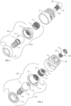
- FIG. 1 and FIG. 2 illustrate an exploded view of one embodiment of an omnidirectional multi-unit abutment 100 comprising four parts: an abutment base 1, swivel mount 2, swivel base 3, and lock screw 4.
- a representative Ti base 5 and prosthetic screw 6 are also shown in the exploded drawings of FIG. 1 and FIG. 2 .
- This omnidirectional multi-unit abutment assembly 100 may be made of titanium or any other suitable material for implant abutment systems including precious and non-precious metals and alloys, ceramics, and high-strength engineering polymers (e.g.
- FIG 3 shows the elements of FIGS. 1 and 2 except for the prosthetic screw 6 in a linear orientation.
- FIG 4 illustrates internal features of the assembly of FIG. 3 along the longitudinal cross-section designator A-A of FIG. 3 . Note that the presence of the Ti base 5 is shown for illustration purposes in FIG. 4 . Ti base 5 is ultimately retained in the prosthesis (not shown) and attached to the omnidirectional multi-unit abutment using prosthetic screw 6 as shown in FIG. 6 .
- Prosthetic screw 6 may be a permanent screw or may be a provisional fastener of the type described in co-owned US Patent 11,311,354 and other applications related by continuity.
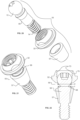
- FIG. 6 is a perspective view of the assembly of FIGS. 1 and 2 in a linear configuration.
- FIG. 5 is a side view of the embodiment tilted at about 30 degrees.
- FIGS. 7-9 show different stages in the installation of this embodiment into an implant and adjustment.
- the abutment base 1 includes a ball or spherical portion 13 which may be approximately 3.25 mm in diameter with an abutment base drive feature 10 on the proximal end. As illustrated, this drive feature may be a hexalobular internal (Torx) drive feature socket of T5 size centered on the longitudinal axis at the top of ball portion 13. Other types of drive tools may be used.
- a threaded portion 14 At the distal end of the abutment base 1 is a threaded portion 14 for attachment to female threads of an implant 16 that is secured into the patient's jaw bone.
- the implant 16 and its attachment to the mandible or maxilla bones are described schematically in this disclosure since the inventive concepts of the omnidirectional multi-unit abutment can be adapted to interface with different abutments.
- the generic implant 16 illustrated in FIG. 7 with female threading is a very common design, but the abutment base attachment 14 and seating 21 may be adapted to conform to other implants.
- the swivel base 3 includes an aperture 19 and an interior curvature portion 15 which is sized and shaped to essentially match the curvature of the ball portion 13 of the abutment base 1.
- the swivel mount 2 illustrated includes internal threading 20 for attaching to the external threads 9 of the lock screw 4. It also includes a Ti base seating feature 22 for supporting and orienting the Ti base 5 when it is mounted with the prosthetic screw to the omnidirectional multi-unit abutment 100.
- the swivel mount may optionally include engagement features 11 that may be used to attach a tool such as a wrench to aid assembly or to restrict the azimuthal orientation (not illustrated) of the Ti base 5.
- Restricting the orientation of a Ti base with matching engagement features of a Ti base and implant abutment is a common technique which is useful for single tooth crowns.
- the omnidirectional multi-unit abutment 100 embodiments herein can be readily adapted to single tooth prostheses by fixing the azimuthal orientation of a non-cylindrically symmetrical Ti base with a matching abutment mounting surface which will not be described in detail.
- the ball portion 13 of the abutment base 1 may be captured between the swivel base 3 and the swivel mount 2 which comprise a swivel shell around the ball portion 13 with the abutment base screw thread portion 14 extending through swivel base aperture 19.
- the aperture 19 must be larger than the abutment seat projection 21.
- the swivel base 3 and swivel mount 2 are preferentially joined at interface joint 12 by continuous welding or spot welding, for example, with a laser after positioning around ball 13 to form base assembly 101. This joining technique provides a strong assembly of a thinner shell over a shorter distance, but other joining techniques may be used to capture the ball portion 13 within a shell. As shown in the cross-sectional view of FIG.
- the mechanical design of the internal curvature 15 and aperture 19 of the assembled swivel base 3 and swivel mount 2 may be designed to prevent the ball portion 13 of the abutment base from escaping the swivel shell.
- the relative sizes and shapes of the aperture 19 and the size and shape of the abutment base 1 at the abutment seat projection 21 determine the range of tilt possible. In general, if the swivel base aperture 19 and the minor diameter or width of the internal threads 20 of the swivel mount are both less than the width of the ball 13, then the ball 13 is captured within a shell absent the lock screw 4.
- the lock screw 4 illustrated has external threads 9 to engage the internal threads 20 of the swivel mount 2. These threads may be, for example, m3x0.35 size.
- Lock screw 4 also has internal threading 7 for attaching the prosthetic screw 6 and an internal drive feature 8 for tool attachment to tighten the lock screw 4 in the swivel mount 2.
- Representative prosthetic screw sizes include m1.4 ⁇ 0.3 threads, m1.6x0.35, UNF 1-72, etc.
- Drive feature 8 may be a socket accommodating common dental drivers including Torx T5 or T6, 0.035" to 0.050" hex or square drivers, or similarly sized straight and star drivers.
- the internal threading 7 and drive feature 8 have a partial overlap along the longitudinal axis of the lock screw. This is a design choice. Complete axial overlap or no axial overlap are other design options.
- the swivel base 3 is configured to engage a segment of the spherical ball feature 13 when lock screw 4 is tightened.
- the figures and cross-sections shown illustrate an embodiment where the swivel base and mount may be positioned and rotated anywhere within a 30-degree cone as shown in FIG. 5 and FIG. 8 .
- the tilt magnitude and orientations of adjustment allowed are a design choice, although 30 degrees of tilt is generally sufficient for most clinical applications.
- the swivel base aperture 19 and the aperture with threading 20 in the swivel mount 2 are smaller than the diameter of the ball portion 13.
- the ball portion of the abutment base 13 may be loosely captured by the swivel base 3 and swivel mount 2 when these two parts are mutually attached. That is, the lock screw 4 does not have to be attached to the swivel mount 2 to have a shell that captures the ball portion 13 with the illustrated embodiment.
- FIG. 4 The cross-sectional view in FIG. 4 of this omnidirectional multi-unit abutment embodiment with Ti base 5 may be used to illustrate some of the advantages of the preferred geometric relationships between elements.
- the ball portion 13 is spherical throughout the range of motion of the shell formed by the swivel base 3, swivel mount 2 and lock screw 4.
- the tilt range limitation due to interference of the swivel base 3 proximate the aperture and the abutment base 1 surface 61 near the abutment seat 21 has been labeled as angle b in FIG. 5 and FIG.9 .
- the interior curvature of the swivel mount 2 is essentially the same as that of the ball portion 13.
- the lock screw 4 also has essentially the same curvature as the ball 13 in the area of contact.
- the interior curvature 15 of the swivel mount 2 is preferentially slightly larger than the curvature of the ball 13.
- the ball portion 13 is contacting the interior curvature 15 of the swivel base 3 and a corresponding interior curvature of the lock screw 4. Since the interior curvature of the swivel mount 2 is larger, it does not contact the ball when the lock screw 4 is fully tightened. This provides a more consistent continuous circular seal of the swivel base to the ball to help block the ingress of biological contamination into the interior of the omnidirectional multi-unit abutment assembly. In the linear configuration of FIG.
- the lock screw 4 also provides an equivalent circular seal with the ball portion 13. As illustrated in the maximum tilt condition of FIG. 9 , the continuous seal of the swivel base 3 to the ball is maintained. However, the seal of the lock screw 4 to the ball 13 is not continuous due to the abutment drive feature 10. However, when the Ti base 5 and prosthetic screw 6 are applied to the omnidirectional multi-unit abutment, the abutment drive feature 10 is effectively sealed.
- the relatively large ring contact of the hollow lock screw 4 to the ball 13 distributes the clamping force over a larger area than the concentrated contact of a solid set screw.
- the extended contact and matching curvature 15 of the swivel base to the ball 13 has been determined to have sufficient frictional grab to allow tightening the lock screw 4 in excess of 25 Ncm without holding the swivel base 3 or swivel mount 4 when parts are made of titanium.
- the relatively large contact area also minimizes distortion of the ball 13 from clamping compared to a concentrated sold set screw, which eases repositioning of the tilt or azimuthal angles without interference from distortions of the ball 13 geometry.
- the relatively large outer diameter of the locking screw 4 also provides sufficient wall thickness between internal threading 7 and external threading 9 for mechanical strength for applying torque to the lock screw 4 with drive tool sizes comparable to the width of the threads of the prosthetic screw 6.
- a relatively large lock screw 4 provides a sufficient number of engaged external lock screw threads 8 with the internal threads 20 of the swivel mount to provide stable clamping forces on the ball 13.
- threads (not illustrated) can also be used at the joint 12 between the swivel mount 2 and swivel base 3, the omnidirectional multi-unit abutment diameter would need to be increased to have sufficient wall thickness and engaging thread depth to have equivalent strength to the relative sizes shown in FIG. 4 .
- limited engagement of screw threads between the swivel mount 2 and swivel base 3 could be used to cause separation when a threshold torque is reached.
- torque limiting include tailoring the preferred welded joint strength described above, increasing the aperture 19 size in the swivel mount, and/or introducing intentionally thinner wall sections in the swivel base proximate the aperture 19 that have lower torque resistance. Although intentional failure by design will likely result in loss of the omnidirectional multi-unit abutment, this may be preferable to excess stress that could result in a future failure of the prosthesis or implant retention.
- the hollow style lock screw 4 and drive geometries illustrated in FIG. 4 provide benefits in dental system installation and maintenance.
- the ball portion 13 of the implant base is captured by the shell portion formed by the swivel mount 2 and swivel base 3.
- the lock screw 4 may be started into the swivel mount 2 and rotated enough to secure it but without contacting the ball portion 13 to form the omnidirectional multi-unit abutment assembly 100.
- the Ti base 5 may be optionally placed on top of the omnidirectional multi-unit abutment assembly and parts aligned along a common axis as shown in FIGS. 3 and 4 .
- Ti base 5 is not required to be in place during installation and orientation of the abutment base 1, swivel base 3, swivel mount 2 and lock screw 4.
- a drive tool 17 may be inserted through the Ti base 5 and the lock screw 4 to engage the drive feature 10 of the abutment base 1 as illustrated in FIG. 7 .
- the engagement fit of the drive tool 17 and abutment base drive feature 10 has sufficient friction to cause the omnidirectional multi-unit abutment 100 to remain on the drive tool 17 to present the omnidirectional multi-unit abutment assembly to the implant 16 as shown in FIG. 7 .
- a slight torquing of the lock screw 4 in the unwind direction may help in this retention.
- the abutment base threads 14 engage the implant 16 and the omnidirectional multi-unit abutment assembly may be screwed down to attain the desired seating of the abutment seat 21 to the implant 16. Since the drive tool engages both the abutment base 1 and lock screw 4, these parts rotate simultaneously. Since the lock screw 4 position is not changing with respect to the abutment base 1, the ball portion 13 is not being gripped between the swivel base 3 and the lock screw 4. The rotational force from the drive tool 17 is drives the abutment base threads 14 deeper into the implant 16.
- the seating portion 21 of the abutment base that contacts the implant can be modified to match the seating geometry of fixed angle abutments.
- the drive feature 10 allows for securing the abutment base 1 threaded portion 14 to the implant 16. The tightening of the abutment base 1 to the implant may proceed until the desired seating pressure at the abutment seat 21 is obtained.
- a representative torque value is about 30 Ncm, although the value will depend upon the implant system employed and may be higher or lower than this. For immediate loading of a prosthesis, the torque value should be less than the torque value used to install the implant into the jaw bone.
- FIG. 8 As shown in FIG. 8 , once the abutment base 1 is secured to the implant 16, the linear configuration of FIG. 7 is no longer needed.
- the tilt and azimuth angle of the swivel mount 2 to receive Ti base 5 desired for prosthesis attachment can be selected by movement of drive tool 18 which is inserted into lock screw 4. Rotating drive tool 18 causes the lock screw 4 and swivel base 3 to clamp ball portion 13 and lock the angulation of the omnidirectional multi-unit abutment 100.
- Engagement features 11 may be included to prevent the lock-screw and swivel base from rotating while the lock screw 4 is tightened. Other engaging features such as small holes or splines may also be used as anti-rotation or azimuthal selection features for this purpose.
- a selection feature on the swivel mount 2 engaging a rotational fixing feature on a Ti base allows the azimuthal angle of the Ti base to be selected and held while tightening the lock screw 4.
- a coaxial two-piece tool that engages the anti-rotation features and includes a drive tool similar to 18 may be used to orient and tighten the swivel mount 2 and lock screw 4 in position on the ball portion 13 of the abutment base 1. Having the Ti base 5 included in the arrangement of FIG. 5 may be convenient for azimuthal selection.
- the drive feature 7 of the lock screw 4 is preferably accessible through the Ti base 5 in both a provisional and the final prostheses. This allows moving and retorquing the lock screw 4 in the proper orientation should it loosen over time, making minor adjustments to improve passive fit, and replacing and realigning one omnidirectional multi-unit abutment 100 within a plurality of omnidirectional multi-unit abutments 100. From a comparison of the drive tool dimension d1 shown in the inset FIG. 7a to the drive tool dimension d2 shown in the inset FIG. 8a , the drive tool 18 shown in FIG. 8 is larger than the drive tool 17 in FIG. 7 . This is not required.
- a benefit of using two different sizes, for example, a T5 driver 17 to drive the abutment base 1 and a T6 driver 18 for securing the lock screw 4 provides extra clearance in the lock screw 4 while driving the abutment base. Since the torque used for driving the abutment base 1 may be chosen to be higher than the torque used for the lock screw 4, a first torque wrench with drive tool 17 and a second torque wrench with drive tool 18 may help ensure the desired torques are obtained.
- the size and shape of the drive tool 17 must pass through the lock screw 4.
- the drive tool 18 in FIG. 8 is prevented from passing completely through the lock screw 4 since the lock screw internal drive interface 8 shown does not extend all the way to the distal side of the lock screw 4. This is a design choice.
- a calibrated objective tool to determine when a predetermined desired torque is applied to the implant base 1 and the lock screw 4. If the abutment base drive interface 10 and lock screw drive interface 8 are the same size and shape, then one tool can be used for drive tool 17 and 18. In this case, after driving the abutment base 1 into the implant 16 as in FIG. 7 , drive tool 17 would only need to be extracted just enough to disengage with the abutment base drive interface 10 before repositioning it to lock the omnidirectional multi-unit abutment 100 position by rotating lock screw 4. If different calibrated torques are desired, two different wrenches could be used with the same drive tool tip size.
- FIG. 9 shows is a cross-sectional view of the omnidirectional multi-unit abutment assembly 100 including prosthetic screw 6 that retains Ti base 5.
- Prosthetic screw 6 may be replaced with a separable fastener (not shown) as described in the referenced US Patent 11,311,354 to facilitate positioning of the Ti base 5 into the prosthesis with a lift off process. Note that even after the Ti base 5 is incorporated into the prosthesis, it is possible to access the lock screw drive interface 8 by removing the prosthetic screw 6. This is essentially changing the configuration from FIG. 9 to FIG. 8 . This benefit will be described in more detail after other embodiments are presented.
- FIG. 10 through FIG. 13 A variation of the embodiment shown in FIG. 1 through FIG. 9 , is illustrated in FIG. 10 through FIG. 13 .
- omnidirectional multi-unit abutment designs may also include embodiments in which the abutment base 30 and ball or spherical feature 31 are initially separate components.
- the ball is approximately 3 mm diameter.
- a nominal seating height of approximately 2.5 mm is illustrated in the figures.
- FIGS. 10-13 The second embodiment illustrated in FIGS. 10-13 is shown with about the same dimensions to work with the same implant 16 and Ti bases 5 as the omnidirectional multi-unit abutment assembly 100 shown in FIGs. 1-9 .
- the seating height between the abutment seat 42 and Ti base seat 41 is also comparable.
- the major difference is that the swivel 32 is captured between portions of a two-part abutment base 30.
- the abutment base 30 in FIG. 12 comprises a separate ball portion 31 attached to a stem portion 34.
- a discrete 31 may be useful, for example, in case a swivel base will not fit through the required abutment diameter without interference. Consequently, the embodiment in FIG. 10 through FIG.
- ball 31 After inserting ball 31 into swivel 32, ball 31 is assembled to base stem portion 34 by any form of mechanical engagement such as press-fitting, heat-shrinking, laser-welding, adhesives, or combinations thereof.
- ball 31 may have a light press-fit onto post 34 and a small radial laser-weld at interface 35. This method reliably joins the ball to the base, while minimizing mechanical precision, providing a fillet at the mating joint 35, and sealing this joint from liquid ingress.
- the minor diameter of the internal threading 38 of the swivel 32 is large enough to allow ball 31 to be inserted through the internal threads 40 of the swivel mount 32.
- the drive interface 45 may be used to orient the ball for assembly. After capturing the swivel 32 and installing and tightening the lock screw 33, the ball 31 contacts the swivel 32 along a seating surface 47. Approximately 17.5 degrees of seating/interference surface is illustrated in FIGS. 12-13 .
- the lock screw 33 also makes contact with the ball 31 along interface 48.
- Various surface finishes and mechanical features may be employed to enhance the locking ability of mating surfaces 48 and 47 to ball 31, such as surface texture, ridges, or ribs.
- the swivel 32 contacts the distal surface of the ball similar to the swivel base 3 of the first embodiment of FIGS. 1-9 , but also provides the Ti base seat 41 to support the Ti base 5 in a known orientation analogous to that provided by of the previous Ti base seat 22 of swivel mount 2.
- the lock screw 33 is similar to the lock screw 4 in the first embodiment. It contains prosthetic screw threads 36, drive socket feature 37, seating surface 48 and external threads 39.
- the proximal end of the ball portion 31 includes drive socket feature 45 that may be accessed through the lock screw 33 similar to lock screw 4 described above.
- lock screw 33 is tightened using drive feature 37, the swivel 32 engages a seating surface 47 of the ball 31 which allows for the lock screw 33 to fix the swivel 32 in the ideal omnidirectional orientation up to thirty degrees off the implant axis and at the desired azimuthal angle.
- Ti base 5 is does not need to be present during installation and orientation of the omnidirectional multi-unit abutment.
- prosthetic screw threading 36 and drive features 45 and 37 and 44 it is possible to utilize a single drive tool for the three steps of tightening the abutment base 30 into the implant (not shown), locking the orientation of the swivel 32 with lock screw 33, and tightening the prosthetic screw 44.
- a single T5 drive tool typical of an M1.6 ⁇ 0.35 prosthetic screw 43 with threading 36 can be used if the drive interfaces 37 , 44 and 45 also have T5 socket characteristics.
- the lock screw drive interface 37 would need to extend through the lock screw 33 (not shown) in order to engage the abutment base drive socket feature 45.
- the portion of the M1.6 prosthetic screw threads removed for the T5 driver has been determined to provide adequate thread integrity to properly retain the prosthetic screw.
- Other standard and custom threads and drive geometry combinations may also be used to allow the use of a single drive tool.
- the width of the abutment base 30 at the implant seating location 42 may be larger than in the first embodiment.
- the threaded end 14 of the abutment base 1 was inserted into the swivel base aperture 19 to contact the ball portion 13.
- the ball portion 13 was captured by joining the swivel mount 2 to the swivel base 3.
- the size of the distal end of the abutment base is not constrained by the aperture at the distal end of the swivel 32 aperture.
- the minor diameter of the lock screw external threads 39 must be larger than the diameter of the ball 31 to allow the ball to be inserted through the swivel 32 to be joined to the abutment base 30.
- a comparison of FIG. 12 with FIG. 4 shows that this results in a shorter depth for engaging threading between the swivel 32 and lock screw 33.
- the abutment base assembly 101 is fabricated from swivel 32 and a ball with taper stem 50 that has a ball feature 13 with drive feature 45 at the proximal end and tapered stem 51 at the distal end.
- the tapered stem 51 is joined to a base 52 having a tapered socket 53 at the proximal end and an abutment base screw thread 14 at the distal end.
- the widest part of the ball with taper stem 50 is the diameter of the ball 13.
- Swivel 32 is captured by inserting the tapered stem 51 into the proximal side of the swivel 32 before inserting the tapered stem 51 into the tapered socket 53.
- FIGS. 15 and 16 show the abutment base assembly 101.
- the tapered stem 51 and base 52 may be joined with different techniques. However, including welding at interface 63 is preferred.
- a comparison of FIG. 16 to FIG. 14 shows that the ball portion 13 of the ball with tapered stem 50 may have improved structural stability compared to abutment base ball 31. This may be important considering the small size of the parts and the desire to have smooth swiveling action and tight sealing of the parts when locked in position.
- the lock screw 49 illustrated in FIG. 14 differs from the lock screws 4 and 33 in previous embodiments by including a hex drive feature 64 on its exterior surface near the proximal end.
- This hex drive feature 64 is provided to aid removal of a failed installation.
- the lock screw drive interface 8 may be plugged so that the drive tool 18 used for installing the omnidirectional multi-unit abutment cannot be inserted.
- a wrench could be applied to the hex feature 64 to remove the lock screw 49.
- these hex features 64 would generally not be accessible with the Ti base 5 in position on the omnidirectional multi-unit abutment.
- the lock screw drive interface 37 is preferred for using the Ti base embedded in the prothesis to help align and lock the omnidirectional multi-unit abutment orientation to improve passive fit. If necessary, a wrench could also be applied to the flat 11 on the side of swivel 32 to help with removal of the plugged lock nut 49 since the Ti base 5 would not be covering it.
- FIG. 17 is a top plan view of the lock screw 49. At the outer edge is the lock screw exterior threading 39 and at the center is the lock screw internal drive interface 8 which is shown as a Torx style.
- the major diameter 66 (dotted line) and minor diameter arc 65 of the lock screw internal threads 7 are shown.
- the minor diameter 65 is not a continuous circle but a series of discontinuous arc segments due to the lock screw internal drive interface 8 that is axially overlapping the lock screw internal threading 7. Note that the lock screw 49 has the lock screw internal drive interface 8 and the internal threading 7 extending all the way through the lock screw 49.
- the amount of material in the lock screw 49 that is available for the drive tool 18 to apply torque to lock the orientation of the omnidirectional multi-unit abutment 100 corresponds to the volume bounded by the major diameter 66 and minor diameter 65 of the internal screw threads 7 minus the material removed to provide the lock screw drive interface 8 socket for the drive tool 18 (not illustrated).
- the size and shape of the drive tool interface 8 can be modified to change the strength of the remaining internal threads 7 for holding the prosthetic screw 6 and maximum torque application to the lock screw 49 to fix orientation before damaging the internal threads 7.
- FIG. 18 is a top plan view of the lock screw 49 with an alternate lock screw internal drive interface 54.
- This drive tool interface 49 has 4-lobes instead of the 6 lobes of the Torx drive tool interface illustrated previously.
- a visual comparison to FIG. 17 is sufficient to show that more of the internal threading is retained compared to FIG. 17 .
- FIG. 19 illustrates a 4-lobe drive tip 62 with the lock screw 49 of FIG. 18 and an abutment base 59 with a matching 4-lobe drive interface 60.
- the other parts of the omnidirectional multi-unit abutment 100 are not shown for clarity. Since drive tip 62 is sized to pass through the lock screw 49, it can be used to drive abutment base 59 into the implant 16 (not shown). Since the drive tip is sized to pass through the Ti base aperture 23 (not shown), it can also rotate the lock screw 49 to fix the position of the omnidirectional multi-unit abutment through the prosthesis (not shown) in which the Ti base 5 (not shown) is embedded.
- FIG. 20 illustrates another embodiment of a two-part abutment base 55 that is assembled to capture a swivel 32.
- the ball portion 13 and the abutment base screw threads 14 are included in an abutment base stem 56.
- the distal end of the abutment ball base stem is inserted into the swivel 32 and then into a hollow sleeve 57 matching the interface requirements of the abutment 16 that will be used.
- the sleeve 57 has a maximum width that is larger than the diameter of the ball portion 13.
- any of the various joining operations mentioned above may be used, although including welding at interface 58 as shown on FIG. 22 is preferred. Also shown in FIG. 22 are two critical dimensions for the assembly process above. The minimum diameter "d" of the through aperture of the swivel 32 must be larger than the maximum width "c" of the abutment base stem 56 below the ball portion. Due to the similarities of this embodiment to previous ones, the other parts and characteristics will not be described.
- FIG. 23 shows a cross-section of the application environment of an installed omnidirectional multi-unit abutment 100 of the first embodiment.
- the implant 16 has been installed in the patient's bone and soft tissue shown schematically as 70.
- the abutment base 1 has been screwed into the implant 16 to a desired torque level.
- the swivel mount 2 has been tilted to essentially its maximum capability comparable to FIG. 8 .
- the Ti base 5 is embedded in the prosthesis 68.
- the occlusal surface 72 of the prosthesis 68 is shown schematically as 72.
- the Ti base 5 is seated on the swivel mount 2, but the prosthetic screw 6 has been removed to allow the lock screw interface 8 to be accessible to a drive tool 71 through prosthetic screw access hole 69.
- FIG. 23 will be used to describe this in more detail.
- the prosthesis 68 with its embedded Ti bases 5 can be removed after removing all of the prosthetic screws 6. Reversing the angle setting and implant attachment processes shown in FIG. 8 and FIG. 7 will remove the failed omnidirectional multi-unit abutment assembly100. Repeating the process of FIG. 7 to attach the new omnidirectional multi-unit abutment 100 to the implant 16 will result in the abutment base 1 being secured into the implant 16, but the shell consisting of the swivel base 3, swivel mount 2 and lock screw 4 will be loose.
- Minimal pressure on the lock screw 4 is sufficient to hold the orientation of the omnidirectional multi-unit abutment so that gravity doesn't cause it to move, but only require a minimal force application to change its orientation.
- Rough positioning of the swivel mount 2 sufficient to engage the Ti base 5 in the prosthesis 68 and manually applying pressure to the prosthesis from the occlusal side 72 will reorient the newly installed omnidirectional multi-unit abutment to align with the Ti base 5 already installed in the prosthesis.
- the lock screw 4 can then be tightened through the aperture 23 in the Ti base 5 in proper position as shown in FIG. 23 . Whether the prosthetic screws 6 from the original omnidirectional multi-unit abutments 100 are used to maintain the alignment pressure on the newly installed omnidirectional multi-unit abutment 100 before tightening the lock screw 6 is optional.
- the lock screw drive interface 8 is accessible through the Ti base 5 and prosthesis 68, a variation of the one-screw passive fit testing protocol may be used to make minor adjustments to the orientation of the omnidirectional multi-unit abutment to improve passive fit at the time of original installation.
- the actual torque value for being appropriately finger tight will depend upon the construction and surface finish of the omnidirectional multi-unit abutment, but will generally less than a few Ncm.
- all of the prosthetic screws 6 are reinstalled and torqued to the recommended value. In this manner, the orientation of each of the omnidirectional multi-unit abutments will be more closely matched to the prosthesis 68.
- a single prosthetic screw 6 is removed to provide access to the lock screw 4 of the omnidirectional multi-unit abutment in that position.
- the lock screw 4 is torqued to its predetermined value.
- the prosthetic screw 6 is reinserted and torqued to the predetermined value. This is repeated until all of the omnidirectional multi-unit abutment lock screws 4 have been tightened and all prosthetic screws 6 are tightened.
- the fine adjustment process above may be modified depending upon the particulars of the initial level of passive fit. For example, it may be desirable to only loosen some of the omnidirectional multi-unit abutment lock screws 4 while leaving others fixed as anchor points from the original prosthesis fitting. This may result from a requirement to compromise passive fit somewhat for better occlusion or other reasons. Or the results of the traditional one screw or screw resistance tests may suggest orientational adjustment of only a subset of the omnidirectional multi-unit abutments or a different order of adjustment. In any case, these passive fit improvements follow directly from the capability of orienting and fixing the omnidirectional multi-unit abutment while the prosthesis is in place.
- the omnidirectional multi-unit abutment 100 embodiments above be adapted to be compatible with Ti bases 5 and threaded implants 16 that have already been qualified and commercially successful.
- the threading and seating to widely available implants improves the inventory equation since the same implants may be used with conventional straight abutments as well as the embodiments above in the same patient.
- the compatibility with widely available screw-attached Ti bases 5 is also seen as an advantage
- inventive features of the described embodiments can be integrated into or adapted to work with newly designed implants that adopt inventive concepts for passive fit improvement or installation efficiency and repair described above. These inventive concepts can also be adapted to work with prostheses that are not attached with screws.
- US Patent 11,311,354 includes different approaches for aligning Ti bases with abutments for incorporation into a prosthesis using a temporary fastener in a lift-off process.
- the basic design of the temporary fasteners illustrated in that co-owned patent can be employed with the omnidirectional multi-unit abutments and Ti bases described above.
Landscapes
- Health & Medical Sciences (AREA)
- Oral & Maxillofacial Surgery (AREA)
- Dentistry (AREA)
- Epidemiology (AREA)
- Life Sciences & Earth Sciences (AREA)
- Animal Behavior & Ethology (AREA)
- General Health & Medical Sciences (AREA)
- Public Health (AREA)
- Veterinary Medicine (AREA)
- Orthopedic Medicine & Surgery (AREA)
- Dental Prosthetics (AREA)
- Dental Tools And Instruments Or Auxiliary Dental Instruments (AREA)
Claims (15)
- Mehrteiliges Abutment (100) zum Ausrichten und Befestigen einer Zahnprothese (68) an einem Implantat (16) mit einer Prothetikschraube (6), wobei die Prothetikschraube (6, 43) einen Kopf (26) und einen Gewindeschaft (25) umfasst, wobei das mehrteilige Abutment Folgendes umfasst:eine Abutment-Basis (1, 30, 52, 56), die eine Längsachse aufweist, wobei die Abutment-Basis (1, 30, 52, 56) Folgendes umfasst:ein proximales Ende, welches einen Kugelabschnitt (13, 31) und eine Antriebsschnittstelle der Abutment-Basis (10, 45, 60) umfasst; undein distales Ende, welches ein Schraubgewinde (14) zur Befestigung an dem Implantat (16) umfasst;eine Drehgelenkschale (2, 3, 32), die eine Innenfläche und eine Außenfläche aufweist, wobei die Drehgelenkschale (2, 3, 32) eine Drehgelenköffnung (19) nahe ihrem distalen Ende und eine Gewindeöffnung (20, 75) an ihrem proximalen Ende beinhaltet; undeine Sicherungsschraube (4, 33, 49), die eine Längsachse aufweist, wobei die Sicherungsschraube Folgendes umfasst:einen Abschnitt mit Außengewinde (9, 39), das mit der Gewindeöffnung (20, 75) der Drehgelenkschale (2, 3, 32) kompatibel ist; undeinen Abschnitt mit Innengewinde (7, 36), das so bemessen ist, dass es in den Schaft der Prothetikschraube (25) eingreift; undeine Antriebsschnittstelle der Sicherungsschraube (8, 37, 54), bei welcher es sich um eine durchgehende Buchse zum Aufnehmen eines Antriebswerkzeugs der Sicherungsschraube (17, 18, 67, 71) handelt, und wobei das Antriebswerkzeug der Sicherungsschraube (17, 18, 67, 71) eine Längsachse und eine maximale Breite aufweist, die kleiner als die maximale Breite des Gewindeschafts (25) der Prothetikschraube (6, 43) ist; undeine Ti-Basis (5), wobei die Ti-Basis (5) eine Öffnung (24) am proximalen Ende aufweist, die größer als der Gewindeschaft (25) der Prothetikschraube und kleiner als der Kopf (26) der Prothetikschraube ist, sowie ein distales Ende, das derart geformt ist, dass es von der Drehgelenkschale (2, 3, 32) in einer bekannten Ausrichtung gestützt wird, und wobei das Antriebswerkzeug der Sicherungsschraube (18, 71) so bemessen ist, dass es ungehindert durch die Öffnung (24) der Ti-Basis (5) geführt werden kann,wobei ein Drehen der Sicherungsschraube (4, 33, 49) eine Ausrichtung der Längsachse der Sicherungsschraube (4, 33, 49) in einer Ausrichtung fixieren kann, die nicht parallel zur Längsachse der Abutment-Basis (1, 30) ist.
- Mehrteiliges Abutment nach Anspruch 1, wobei der Kugelabschnitt (13, 31) der Abutment-Basis (1, 30, 52, 56) zwischen einem Abschnitt der Innenfläche der Drehgelenkschale (2, 3, 32) und der Sicherungsschraube (4, 33, 49) festgehalten wird.
- Mehrteiliges Abutment nach Anspruch 1, wobei die Drehgelenkschale eine Drehgelenkbasis und eine Drehgelenkhalterung umfasst, die mechanisch zusammengefügt werden, um den Kugelabschnitt der Abutment-Basis aufzunehmen.
- Mehrteiliges Abutment nach Anspruch 1, wobei es sich bei der Antriebsschnittstelle der Abutment-Basis (10, 45, 60) um eine Buchse zum Aufnehmen eines Antriebswerkzeugs der Abutment-Basis (17) handelt und wobei das Antriebswerkzeug der Abutment-Basis (17) eine Längsachse und eine Spitze (62) des Antriebswerkzeugs für die Abutment-Basis aufweist, die so geformt ist, dass sie in die Antriebsschnittstelle der Abutment-Basis (10, 45, 60) eingreift.
- Mehrteiliges Abutment nach Anspruch 1, wobei das Antriebswerkzeug der Sicherungsschraube (17, 18, 67, 71) eine Längsachse und eine maximale Breite aufweist, die kleiner als die maximale Breite des Gewindeschafts (25) der Prothetikschraube (6, 43) ist.
- Mehrteiliges Abutment nach Anspruch 5, wobei die Spitze (62) des Antriebswerkzeugs für das Abutment so bemessen ist, dass sie durch die Sicherungsschraube (4, 33, 49) passt.
- Mehrteiliges Abutment nach Anspruch 6, wobei die Spitze (62) des Antriebswerkzeugs für das Abutment zum Festziehen der Abutment-Basis (1, 30, 52, 56) in das Implantat (16) mit einem ersten Drehmoment ohne gleichzeitiges Festziehen der Sicherungsschraube (4, 33, 49) ausgelegt ist, um die Ausrichtung der Drehgelenkschale (2, 3, 32) zu fixieren.
- Mehrteiliges Abutment nach Anspruch 1, wobei die Ausrichtung der Drehgelenkschale (2, 3, 32) durch ein Neigen des Antriebswerkzeugs der Sicherungsschraube (62, 67, 71) weg von der linearen Achse der Abutment-Basis (1, 30, 52, 56) und ein Festziehen der Sicherungsschraube (4, 33, 49) mit einem zweiten Drehmoment ausgewählt wird.
- Mehrteiliges Abutment nach Anspruch 8, wobei die Spitze (62) des Antriebswerkzeugs für das Abutment zum Festziehen der Sicherungsschraube (4, 33, 49) verwendet wird.
- Mehrteiliges Abutment nach Anspruch 1, wobei die Drehgelenkschale (2, 3, 32) eine Drehgelenkbasis (3) und eine Drehgelenkhalterung (2) umfasst, die mechanisch zusammengefügt werden, um den Kugelabschnitt (13, 31) der Abutment-Basis (1, 30, 52, 56) aufzunehmen.
- Mehrteiliges Abutment nach Anspruch 1, wobei die Ti-Basis unter Verwendung eines Abhebeprozesses mit einem temporären Befestigungselement in die Prothese aufgenommen wird, wobei das temporäre Befestigungselement Folgendes umfasst:einen Zapfen, der eine Achse, ein erstes Zapfenende und ein zweites Zapfenende aufweist, wobei das erste Zapfenende zur Schraubbefestigung an der Sicherungsschraube mit einem Gewinde versehen ist; undeine Kappe, wobei die Kappe an dem zweiten Zapfenende befestigt ist;und wobei das temporäre Ausrichtungsbefestigungselement dazu konfiguriert ist, die Ti-Basis gegen die Drehgelenkschale zu drücken, indem eine Drehkraft auf die Kappe ausgeübt wird, um das erste Zapfenende in die Sicherungsschraube zu schrauben, und wobei die Kappe durch eine Freigabekraft, die von dem erste Zapfenende weg gerichtet ist, von dem Zapfen getrennt werden kann.
- System zum Ausrichten und Befestigen einer Zahnprothese (68) an einem Implantat (16), welches Folgendes umfasst:ein mehrteiliges Abutment (100) nach Anspruch 1; undein oder mehrere Antriebswerkzeuge (17, 18, 62, 71), die zum Eingreifen in die Antriebsschnittstelle der Abutment-Basis (10, 45, 60) und/oder die Sicherungsschraube (4, 33, 49) ausgelegt sind; wobei mindestens ein Antriebswerkzeug des einen oder der mehreren Antriebswerkzeuge durch die Öffnung (24) der Ti-Basis (5) eingeführt werden kann, um in die Sicherungsschraube (4, 33, 49) einzugreifen; und wobei ein Festziehen der Sicherungsschraube (4, 33, 49) Druck auf den Kugelabschnitt (13, 31) ausübt, um die Ausrichtung der Drehgelenkschale (2, 3, 32) zu fixieren,wobei die Sicherungsschraube (4, 33, 39) eine Längsöffnung aufweist und wobei die Öffnung so bemessen ist, dass sich das Antriebswerkzeug für das Abutment (17, 18, 62, 71) durch die Sicherungsschraube (4, 33, 39) erstrecken kann.
- System nach Anspruch 12, wobei die Ti-Basis (5) in eine Prothese (68) aufgenommen wird und wobei eine Kraft auf die Prothese (68) ausgeübt wird, um das mehrteilige Implantat-Abutment (100) an der Ti-Basis (5) auszurichten, wenn die Sicherungsschraube (4, 33, 39) festgezogen wird.
- System nach Anspruch 12, welches ferner die Prothetikschraube (6, 43) umfasst, wobei die Prothetikschraube (6, 43) Folgendes umfasst:einen Kopfabschnitt (26) mit einer Breite, die größer als die Öffnung (24) der Ti-Basis (5) ist; undeinen Gewindeschaftabschnitt (25) mit einer Breite, die kleiner als die Öffnung (24) der Ti-Basis ist; undwobei die Sicherungsschraube (4, 33, 39) ein Gewinde (7) zum Aufnehmen des Gewindes (25) der Prothetikschraube (6, 43) beinhaltet.
- System nach Anspruch 12, wobei die Abutment-Basis aus zwei Komponenten besteht und wobei die beiden Teile so miteinander verbunden sind, dass die Öffnung der Drehgelenkschale zwischen den beiden Komponenten liegt.
Applications Claiming Priority (2)
| Application Number | Priority Date | Filing Date | Title |
|---|---|---|---|
| US202163196227P | 2021-06-03 | 2021-06-03 | |
| PCT/US2022/032234 WO2022256699A1 (en) | 2021-06-03 | 2022-06-03 | Omnidirectional multi-unit abutment system for screw-attached dental prostheses |
Publications (3)
| Publication Number | Publication Date |
|---|---|
| EP4312872A1 EP4312872A1 (de) | 2024-02-07 |
| EP4312872A4 EP4312872A4 (de) | 2024-02-14 |
| EP4312872B1 true EP4312872B1 (de) | 2024-12-25 |
Family
ID=84285674
Family Applications (1)
| Application Number | Title | Priority Date | Filing Date |
|---|---|---|---|
| EP22816962.9A Active EP4312872B1 (de) | 2021-06-03 | 2022-06-03 | Omnidirektionales mehrteiliges abutmentsystem für schraubenbefestigte zahnprothesen |
Country Status (9)
| Country | Link |
|---|---|
| US (2) | US12023220B2 (de) |
| EP (1) | EP4312872B1 (de) |
| JP (1) | JP7630017B2 (de) |
| KR (1) | KR102673153B1 (de) |
| CN (1) | CN117500453B (de) |
| AU (1) | AU2022286486B2 (de) |
| CA (1) | CA3215615C (de) |
| IL (1) | IL309005B2 (de) |
| WO (1) | WO2022256699A1 (de) |
Families Citing this family (9)
| Publication number | Priority date | Publication date | Assignee | Title |
|---|---|---|---|---|
| US12303352B2 (en) | 2021-06-03 | 2025-05-20 | Full Arch Solutions, Llc | Omni-directional multi-unit abutment dental systems |
| KR102673153B1 (ko) | 2021-06-03 | 2024-06-05 | 풀 아치 솔루션즈, 엘엘씨 | 나사 부착형 치과 보철물을 위한 전방향 다중 유닛 어버트먼트 시스템 |
| KR102363645B1 (ko) * | 2021-07-26 | 2022-02-15 | 장천석 | 스크류 홀의 직경을 줄이는 커넥터를 포함한 임플란트용 어버트먼트 |
| US20240164873A1 (en) * | 2022-11-20 | 2024-05-23 | Jeremy Lane Thompson | Adjustable-angle multi-unit abutment |
| EP4431054B1 (de) * | 2023-03-15 | 2026-04-22 | Talladium España, S.L. | Inneres transeptheliales abtutment |
| WO2024211923A2 (en) * | 2023-04-07 | 2024-10-10 | Thompson Jeremy Lane | Adjustable-angle multi-unit abutment |
| EP4709317A2 (de) * | 2023-06-22 | 2026-03-18 | Full Arch Solutions, LLC | Selbstausrichtendes mehrteiliges abutmentsystem für zahnprothesen |
| WO2025191306A1 (en) * | 2024-03-13 | 2025-09-18 | Khoury Nikola | A tibase for a multi unit abutment |
| SE2450361A1 (en) * | 2024-04-05 | 2025-10-06 | Bmc Dental Ab | A fastening system |
Family Cites Families (67)
| Publication number | Priority date | Publication date | Assignee | Title |
|---|---|---|---|---|
| SE328961B (de) | 1970-03-25 | 1970-09-28 | Aga Ab | |
| US4070122A (en) | 1976-09-13 | 1978-01-24 | Tecumseh Products Company | Ball and socket joint and method of making |
| AT375012B (de) * | 1982-09-20 | 1984-06-25 | Buermoos Dentalwerk | Zahnaerztliches kieferimplantat |
| DE3531389A1 (de) | 1985-09-03 | 1987-03-05 | Kirsch Axel | Enossales implantat |
| US4713004A (en) * | 1986-09-04 | 1987-12-15 | Vent Plant Corporation | Submergible screw-type dental implant and method of utilization |
| US4932868A (en) | 1986-09-04 | 1990-06-12 | Vent-Plant Corporation | Submergible screw-type dental implant and method of utilization |
| US4842518A (en) * | 1986-09-04 | 1989-06-27 | Vent-Plant Corporation | Submergible screw-type dental implant and method of utilization |
| US4832601A (en) | 1987-12-04 | 1989-05-23 | Hall Surgical | Adjustable support for a prosthetic tooth and method |
| US4988297A (en) | 1988-03-01 | 1991-01-29 | Implant Innovations, Inc. | Alignment corrector for dental implants |
| US4907969A (en) | 1988-04-14 | 1990-03-13 | Ward Whitley S | Universal dental prosthesis retention system |
| FR2655534B1 (fr) | 1989-12-12 | 1997-10-24 | Patrick Peltier | Implant dentaire. |
| SE466935B (sv) | 1990-09-04 | 1992-05-04 | Oscar Wilje | Anordning foer foerankring av proteser |
| US5133662A (en) | 1991-09-03 | 1992-07-28 | Metcalfe Edwin R | Tooth implant device |
| GB9124417D0 (en) | 1991-11-16 | 1992-01-08 | Rosa Michael F | Universal joint for dental abutment implant |
| DE9202656U1 (de) | 1992-02-29 | 1992-04-23 | ZL Microdent-Attachment GmbH, 5805 Breckerfeld | Imlantataufbau |
| DE4224785C2 (de) | 1992-07-27 | 1997-04-30 | Imz Fertigung Vertrieb | Enossales Zahnimplantat für einen festsitzenden Zahnersatz sowie Einsetzwerkzeug |
| US5302125A (en) | 1992-10-22 | 1994-04-12 | Kownacki Charles D | Dental prosthetic implant |
| US5873721A (en) * | 1993-12-23 | 1999-02-23 | Adt Advanced Dental Technologies, Ltd. | Implant abutment systems, devices, and techniques |
| US5417570A (en) | 1994-01-03 | 1995-05-23 | Zest Anchors, Inc. | Dental anchor assembly |
| US5599185A (en) | 1994-09-28 | 1997-02-04 | Greenberg Surgical Technologies, Llc | Dental implant healing abutment |
| FR2727307B3 (fr) | 1994-11-25 | 1996-12-20 | Claude Segura | Dispositif de liaison pour protheses dentaires adaptable sur des racines naturelles ou artificielles |
| DE19653229A1 (de) | 1996-12-20 | 1998-06-25 | Manfred Stroppe | Kieferchirurgisches Sekundärteil |
| US6287115B1 (en) | 1998-11-17 | 2001-09-11 | L. Paul Lustig | Dental implant and tool and method for effecting a dental restoration using the same |
| DE19959366A1 (de) | 1999-12-09 | 2001-06-13 | Stefan Wintermantel | Implantataufbau für ein enossales Zahnimplantat |
| DE10133932B4 (de) | 2001-06-16 | 2007-12-20 | Kaun, Jürgen | Zahnimplantat |
| KR100428934B1 (ko) * | 2001-10-11 | 2004-04-29 | 주식회사 덴티움 | 임플란트 시술용 임프레션 코핑 |
| US6843653B2 (en) | 2002-06-04 | 2005-01-18 | Joseph Carlton | Dental implant |
| US6981871B2 (en) | 2002-07-05 | 2006-01-03 | Zest Anchors, Inc. | Dental attachment assembly and method |
| EP1547543A1 (de) | 2003-12-23 | 2005-06-29 | Steffen Dr. Heitland | Abutment für Dentalimplantate |
| US7214063B2 (en) | 2004-07-29 | 2007-05-08 | Yechiel Cohen | Implant system particularly useful for fixing dental prostheses to bone |
| US20080261174A1 (en) | 2007-04-23 | 2008-10-23 | Gittleman Neal B | Expanding Ball Lock Oral Prosthesis Alignment Apparatus |
| EP2417928B2 (de) | 2007-09-17 | 2019-03-06 | Straumann Holding AG | Verbindungsanordnung zwischen einem Dentalimplantat und einem Abutment |
| US20100151420A1 (en) * | 2008-12-11 | 2010-06-17 | Ranck Roger S | Fixtures for dental implants |
| US20100291507A1 (en) | 2009-05-13 | 2010-11-18 | Custom Spine, Inc. | Polyaxial Dental Implant |
| US8142193B2 (en) * | 2009-06-25 | 2012-03-27 | Bar Shalom Eliezer | Compound angular joint for connecting an abutment to a dental implant in a predefined angle |
| EP2696800B1 (de) | 2011-04-15 | 2019-03-27 | Jbsg Management LLC | Polyaxiales zahnimplantatsystem |
| ITUD20110065A1 (it) | 2011-04-27 | 2012-10-28 | 2 Al S A S Di Amadio Alessandra & C | Dispositivo odontoiatrico per il posizionamento di una protesi dentaria |
| KR101570279B1 (ko) | 2011-05-16 | 2015-11-18 | 헤레우스 쿨제르 노르딕 아베 | 치과용 상부 구조물 및 그 제조 방법 |
| WO2012170663A1 (en) * | 2011-06-08 | 2012-12-13 | Zest Ip Holdings Llc | Fixed detachable dental attachment device, assembly and methods of using the same |
| DE102011086711A1 (de) | 2011-11-21 | 2013-05-23 | Promedia A. Ahnfeldt Gmbh | Verankerungsvorrichtung zum Befestigen von orthodontischen Drähten oder kieferorthopädischen Apparaturen für kieferorthopädische Korrekturbehandlungen |
| ES2386589B2 (es) | 2012-04-02 | 2013-03-25 | Terrats Mecanizados, S.L. | Aditamento protésico |
| KR200471489Y1 (ko) | 2012-04-04 | 2014-02-28 | 왕제원 | 각도조절과 위치조절이 자유로운 틀니 고정용 어태치먼트 |
| GB2506634A (en) * | 2012-10-04 | 2014-04-09 | William Duncan Robertson | A joint consolidator |
| BR102012029369A2 (pt) | 2012-11-19 | 2014-09-23 | Esteban Xam-Mar Mangrane | Aperfeiçoamentos introduzidos em conjunto pilar dinâmico |
| US9452029B2 (en) | 2012-12-11 | 2016-09-27 | Zest Ip Holdings Llc | Fixed hybrid dental attachment device and methods of using same |
| JP6346903B2 (ja) | 2013-01-07 | 2018-06-20 | エルスナー、エドヴィンELSNER, Edvin | インプラント内に弾性的に固定される歯科装置固定ユニット、及び/又は、任意選択的な角度位置調整を可能にする、インプラント内に固定される歯科装置固定ユニット |
| WO2015040250A1 (es) | 2013-09-23 | 2015-03-26 | Esteban Xam-Mar Mangrane | Elemento de interfase para prótesis dentales |
| KR101386560B1 (ko) * | 2013-11-21 | 2014-04-17 | 김윤자 | 치과용 임플란트 구조물 |
| US9687320B2 (en) | 2014-02-17 | 2017-06-27 | Sterngold Dental, Llc | Dental device for anchoring a denture to an implant |
| KR101407224B1 (ko) | 2014-03-06 | 2014-06-17 | 왕제원 | 틀니 고정용 어태치먼트 |
| US9033709B1 (en) | 2014-06-06 | 2015-05-19 | Zest Ip Holdings, Llc | Dental attachment assembly cap and method of use |
| US9931181B2 (en) | 2014-07-22 | 2018-04-03 | Zest Ip Holdings, Llc | Fixed hybrid dental attachment assembly and methods of use |
| US9827074B2 (en) | 2014-07-22 | 2017-11-28 | Zest Ip Holdings, Llc | Fixed hybrid dental attachment device and methods of use |
| WO2016139671A1 (en) | 2015-03-04 | 2016-09-09 | Alintech Ltd. | Dental implant and abutment |
| US9320577B1 (en) | 2015-03-27 | 2016-04-26 | King Saud University | Joint assembly for dental implant abutment |
| HU231077B1 (hu) | 2015-04-21 | 2020-06-29 | Elsner Global Llc | Szerelvény fogműnek egy fogászati implantátumhoz való rögzítésére |
| IL244461A (en) | 2016-03-06 | 2017-06-29 | Jacobsen Hagay | Adjustable adapter for biological structure installation |
| KR101911081B1 (ko) | 2016-12-07 | 2018-10-23 | 박지훈 | 치과용 임플란트 |
| CN107280790B (zh) | 2017-07-20 | 2019-11-12 | 西安康拓医疗技术有限公司 | 一种种植体修复用角度可调式取模柱 |
| DE102019203222A1 (de) | 2018-05-07 | 2019-11-07 | Epiphanostics GmbH | Implantataufbau für ein enossales Zahnimplantat |
| US11311354B2 (en) * | 2018-10-09 | 2022-04-26 | Smart Denture Conversions, Llc | Screw-attached pick-up dental coping system and methods |
| WO2020100106A2 (en) | 2018-11-15 | 2020-05-22 | Gasparon Ugo | Dental implant |
| KR101966407B1 (ko) | 2018-11-21 | 2019-04-05 | 주식회사 하이니스 | 어버트먼트 조립체 |
| KR102034995B1 (ko) | 2019-06-19 | 2019-10-21 | 김성민 | 임플란트용 어버트먼트 및 그 제조방법 |
| EP3831335B1 (de) | 2019-12-02 | 2023-06-07 | Terrats Medical, S.L. | Zahnimplantologie-anordnung |
| IT202000023839A1 (it) | 2020-10-09 | 2022-04-09 | Ugo Gasparon | Impianto dentale |
| KR102673153B1 (ko) | 2021-06-03 | 2024-06-05 | 풀 아치 솔루션즈, 엘엘씨 | 나사 부착형 치과 보철물을 위한 전방향 다중 유닛 어버트먼트 시스템 |
-
2022
- 2022-06-03 KR KR1020237045214A patent/KR102673153B1/ko active Active
- 2022-06-03 IL IL309005A patent/IL309005B2/en unknown
- 2022-06-03 CA CA3215615A patent/CA3215615C/en active Active
- 2022-06-03 US US18/548,553 patent/US12023220B2/en active Active
- 2022-06-03 CN CN202280039807.9A patent/CN117500453B/zh active Active
- 2022-06-03 WO PCT/US2022/032234 patent/WO2022256699A1/en not_active Ceased
- 2022-06-03 AU AU2022286486A patent/AU2022286486B2/en active Active
- 2022-06-03 JP JP2023573053A patent/JP7630017B2/ja active Active
- 2022-06-03 US US17/832,143 patent/US12178680B2/en active Active
- 2022-06-03 EP EP22816962.9A patent/EP4312872B1/de active Active
Also Published As
| Publication number | Publication date |
|---|---|
| US12023220B2 (en) | 2024-07-02 |
| IL309005B2 (en) | 2025-07-01 |
| KR102673153B1 (ko) | 2024-06-05 |
| WO2022256699A1 (en) | 2022-12-08 |
| KR20240008380A (ko) | 2024-01-18 |
| IL309005A (en) | 2024-01-01 |
| JP2024524840A (ja) | 2024-07-09 |
| US12178680B2 (en) | 2024-12-31 |
| CA3215615C (en) | 2025-01-21 |
| EP4312872A4 (de) | 2024-02-14 |
| JP7630017B2 (ja) | 2025-02-14 |
| CA3215615A1 (en) | 2022-12-08 |
| US20220387144A1 (en) | 2022-12-08 |
| BR112023024391A2 (pt) | 2024-02-15 |
| CN117500453A (zh) | 2024-02-02 |
| IL309005B1 (en) | 2025-03-01 |
| AU2022286486B2 (en) | 2023-11-09 |
| US20240090982A1 (en) | 2024-03-21 |
| EP4312872A1 (de) | 2024-02-07 |
| CN117500453B (zh) | 2025-03-25 |
Similar Documents
| Publication | Publication Date | Title |
|---|---|---|
| EP4312872B1 (de) | Omnidirektionales mehrteiliges abutmentsystem für schraubenbefestigte zahnprothesen | |
| CN108064150B (zh) | 无螺钉的牙齿植入物连接件 | |
| US11877909B2 (en) | Dental implant set | |
| US6786725B2 (en) | Dental implant and tool and method for effecting a dental restoration using the same | |
| US6843653B2 (en) | Dental implant | |
| JP6346903B2 (ja) | インプラント内に弾性的に固定される歯科装置固定ユニット、及び/又は、任意選択的な角度位置調整を可能にする、インプラント内に固定される歯科装置固定ユニット | |
| KR20120117893A (ko) | 치과용 플랫폼 조립체 및 방법들 | |
| IL158789A (en) | Dental implant system | |
| US10507085B2 (en) | Structure enabling continuous angular adjustment for fixing a single dental device into an implant | |
| US12303352B2 (en) | Omni-directional multi-unit abutment dental systems | |
| BR112023024391B1 (pt) | Sistema e método para alinhamento e fixação de uma prótese dentária a um implante com um parafuso protético | |
| AU2024314865A1 (en) | Self-aligning multi-unit abutment system for dental prostheses | |
| JP2018531713A (ja) | 回転防止上部接続部を有する経上皮スリーブを備えた、歯科用インプラントおよび補綴部品のセット |
Legal Events
| Date | Code | Title | Description |
|---|---|---|---|
| STAA | Information on the status of an ep patent application or granted ep patent |
Free format text: STATUS: THE INTERNATIONAL PUBLICATION HAS BEEN MADE |
|
| PUAI | Public reference made under article 153(3) epc to a published international application that has entered the european phase |
Free format text: ORIGINAL CODE: 0009012 |
|
| STAA | Information on the status of an ep patent application or granted ep patent |
Free format text: STATUS: REQUEST FOR EXAMINATION WAS MADE |
|
| STAA | Information on the status of an ep patent application or granted ep patent |
Free format text: STATUS: EXAMINATION IS IN PROGRESS |
|
| 17P | Request for examination filed |
Effective date: 20231026 |
|
| AK | Designated contracting states |
Kind code of ref document: A1 Designated state(s): AL AT BE BG CH CY CZ DE DK EE ES FI FR GB GR HR HU IE IS IT LI LT LU LV MC MK MT NL NO PL PT RO RS SE SI SK SM TR |
|
| A4 | Supplementary search report drawn up and despatched |
Effective date: 20240115 |
|
| RIC1 | Information provided on ipc code assigned before grant |
Ipc: A61C 13/00 20060101ALI20240109BHEP Ipc: A61C 9/00 20060101ALI20240109BHEP Ipc: A61C 8/00 20060101AFI20240109BHEP |
|
| 17Q | First examination report despatched |
Effective date: 20240126 |
|
| DAV | Request for validation of the european patent (deleted) | ||
| DAX | Request for extension of the european patent (deleted) | ||
| GRAP | Despatch of communication of intention to grant a patent |
Free format text: ORIGINAL CODE: EPIDOSNIGR1 |
|
| STAA | Information on the status of an ep patent application or granted ep patent |
Free format text: STATUS: GRANT OF PATENT IS INTENDED |
|
| INTG | Intention to grant announced |
Effective date: 20240923 |
|
| GRAS | Grant fee paid |
Free format text: ORIGINAL CODE: EPIDOSNIGR3 |
|
| GRAA | (expected) grant |
Free format text: ORIGINAL CODE: 0009210 |
|
| STAA | Information on the status of an ep patent application or granted ep patent |
Free format text: STATUS: THE PATENT HAS BEEN GRANTED |
|
| AK | Designated contracting states |
Kind code of ref document: B1 Designated state(s): AL AT BE BG CH CY CZ DE DK EE ES FI FR GB GR HR HU IE IS IT LI LT LU LV MC MK MT NL NO PL PT RO RS SE SI SK SM TR |
|
| RAP3 | Party data changed (applicant data changed or rights of an application transferred) |
Owner name: FULL ARCH SOLUTIONS, LLC |
|
| REG | Reference to a national code |
Ref country code: GB Ref legal event code: FG4D |
|
| REG | Reference to a national code |
Ref country code: CH Ref legal event code: EP |
|
| REG | Reference to a national code |
Ref country code: IE Ref legal event code: FG4D |
|
| REG | Reference to a national code |
Ref country code: DE Ref legal event code: R096 Ref document number: 602022009178 Country of ref document: DE |
|
| P01 | Opt-out of the competence of the unified patent court (upc) registered |
Free format text: CASE NUMBER: APP_7675/2025 Effective date: 20250214 |
|
| REG | Reference to a national code |
Ref country code: LT Ref legal event code: MG9D |
|
| PG25 | Lapsed in a contracting state [announced via postgrant information from national office to epo] |
Ref country code: HR Free format text: LAPSE BECAUSE OF FAILURE TO SUBMIT A TRANSLATION OF THE DESCRIPTION OR TO PAY THE FEE WITHIN THE PRESCRIBED TIME-LIMIT Effective date: 20241225 |
|
| PG25 | Lapsed in a contracting state [announced via postgrant information from national office to epo] |
Ref country code: FI Free format text: LAPSE BECAUSE OF FAILURE TO SUBMIT A TRANSLATION OF THE DESCRIPTION OR TO PAY THE FEE WITHIN THE PRESCRIBED TIME-LIMIT Effective date: 20241225 |
|
| PG25 | Lapsed in a contracting state [announced via postgrant information from national office to epo] |
Ref country code: BG Free format text: LAPSE BECAUSE OF FAILURE TO SUBMIT A TRANSLATION OF THE DESCRIPTION OR TO PAY THE FEE WITHIN THE PRESCRIBED TIME-LIMIT Effective date: 20241225 |
|
| PG25 | Lapsed in a contracting state [announced via postgrant information from national office to epo] |
Ref country code: NO Free format text: LAPSE BECAUSE OF FAILURE TO SUBMIT A TRANSLATION OF THE DESCRIPTION OR TO PAY THE FEE WITHIN THE PRESCRIBED TIME-LIMIT Effective date: 20250325 |
|
| PG25 | Lapsed in a contracting state [announced via postgrant information from national office to epo] |
Ref country code: LV Free format text: LAPSE BECAUSE OF FAILURE TO SUBMIT A TRANSLATION OF THE DESCRIPTION OR TO PAY THE FEE WITHIN THE PRESCRIBED TIME-LIMIT Effective date: 20241225 Ref country code: GR Free format text: LAPSE BECAUSE OF FAILURE TO SUBMIT A TRANSLATION OF THE DESCRIPTION OR TO PAY THE FEE WITHIN THE PRESCRIBED TIME-LIMIT Effective date: 20250326 |
|
| PG25 | Lapsed in a contracting state [announced via postgrant information from national office to epo] |
Ref country code: RS Free format text: LAPSE BECAUSE OF FAILURE TO SUBMIT A TRANSLATION OF THE DESCRIPTION OR TO PAY THE FEE WITHIN THE PRESCRIBED TIME-LIMIT Effective date: 20250325 |
|
| REG | Reference to a national code |
Ref country code: NL Ref legal event code: MP Effective date: 20241225 |
|
| PG25 | Lapsed in a contracting state [announced via postgrant information from national office to epo] |
Ref country code: NL Free format text: LAPSE BECAUSE OF FAILURE TO SUBMIT A TRANSLATION OF THE DESCRIPTION OR TO PAY THE FEE WITHIN THE PRESCRIBED TIME-LIMIT Effective date: 20241225 |
|
| REG | Reference to a national code |
Ref country code: AT Ref legal event code: MK05 Ref document number: 1753543 Country of ref document: AT Kind code of ref document: T Effective date: 20241225 |
|
| PG25 | Lapsed in a contracting state [announced via postgrant information from national office to epo] |
Ref country code: SM Free format text: LAPSE BECAUSE OF FAILURE TO SUBMIT A TRANSLATION OF THE DESCRIPTION OR TO PAY THE FEE WITHIN THE PRESCRIBED TIME-LIMIT Effective date: 20241225 |
|
| PG25 | Lapsed in a contracting state [announced via postgrant information from national office to epo] |
Ref country code: PL Free format text: LAPSE BECAUSE OF FAILURE TO SUBMIT A TRANSLATION OF THE DESCRIPTION OR TO PAY THE FEE WITHIN THE PRESCRIBED TIME-LIMIT Effective date: 20241225 |
|
| PGFP | Annual fee paid to national office [announced via postgrant information from national office to epo] |
Ref country code: DE Payment date: 20250402 Year of fee payment: 4 |
|
| PG25 | Lapsed in a contracting state [announced via postgrant information from national office to epo] |
Ref country code: ES Free format text: LAPSE BECAUSE OF FAILURE TO SUBMIT A TRANSLATION OF THE DESCRIPTION OR TO PAY THE FEE WITHIN THE PRESCRIBED TIME-LIMIT Effective date: 20241225 |
|
| PG25 | Lapsed in a contracting state [announced via postgrant information from national office to epo] |
Ref country code: IS Free format text: LAPSE BECAUSE OF FAILURE TO SUBMIT A TRANSLATION OF THE DESCRIPTION OR TO PAY THE FEE WITHIN THE PRESCRIBED TIME-LIMIT Effective date: 20250425 |
|
| PG25 | Lapsed in a contracting state [announced via postgrant information from national office to epo] |
Ref country code: PT Free format text: LAPSE BECAUSE OF FAILURE TO SUBMIT A TRANSLATION OF THE DESCRIPTION OR TO PAY THE FEE WITHIN THE PRESCRIBED TIME-LIMIT Effective date: 20250428 |
|
| PG25 | Lapsed in a contracting state [announced via postgrant information from national office to epo] |
Ref country code: EE Free format text: LAPSE BECAUSE OF FAILURE TO SUBMIT A TRANSLATION OF THE DESCRIPTION OR TO PAY THE FEE WITHIN THE PRESCRIBED TIME-LIMIT Effective date: 20241225 |
|
| PGFP | Annual fee paid to national office [announced via postgrant information from national office to epo] |
Ref country code: FR Payment date: 20250401 Year of fee payment: 4 |
|
| PG25 | Lapsed in a contracting state [announced via postgrant information from national office to epo] |
Ref country code: RO Free format text: LAPSE BECAUSE OF FAILURE TO SUBMIT A TRANSLATION OF THE DESCRIPTION OR TO PAY THE FEE WITHIN THE PRESCRIBED TIME-LIMIT Effective date: 20241225 Ref country code: AT Free format text: LAPSE BECAUSE OF FAILURE TO SUBMIT A TRANSLATION OF THE DESCRIPTION OR TO PAY THE FEE WITHIN THE PRESCRIBED TIME-LIMIT Effective date: 20241225 |
|
| PG25 | Lapsed in a contracting state [announced via postgrant information from national office to epo] |
Ref country code: SK Free format text: LAPSE BECAUSE OF FAILURE TO SUBMIT A TRANSLATION OF THE DESCRIPTION OR TO PAY THE FEE WITHIN THE PRESCRIBED TIME-LIMIT Effective date: 20241225 |
|
| PG25 | Lapsed in a contracting state [announced via postgrant information from national office to epo] |
Ref country code: CZ Free format text: LAPSE BECAUSE OF FAILURE TO SUBMIT A TRANSLATION OF THE DESCRIPTION OR TO PAY THE FEE WITHIN THE PRESCRIBED TIME-LIMIT Effective date: 20241225 |
|
| PG25 | Lapsed in a contracting state [announced via postgrant information from national office to epo] |
Ref country code: IT Free format text: LAPSE BECAUSE OF FAILURE TO SUBMIT A TRANSLATION OF THE DESCRIPTION OR TO PAY THE FEE WITHIN THE PRESCRIBED TIME-LIMIT Effective date: 20241225 |
|
| PG25 | Lapsed in a contracting state [announced via postgrant information from national office to epo] |
Ref country code: SE Free format text: LAPSE BECAUSE OF FAILURE TO SUBMIT A TRANSLATION OF THE DESCRIPTION OR TO PAY THE FEE WITHIN THE PRESCRIBED TIME-LIMIT Effective date: 20241225 |
|
| REG | Reference to a national code |
Ref country code: DE Ref legal event code: R097 Ref document number: 602022009178 Country of ref document: DE |
|
| PG25 | Lapsed in a contracting state [announced via postgrant information from national office to epo] |
Ref country code: DK Free format text: LAPSE BECAUSE OF FAILURE TO SUBMIT A TRANSLATION OF THE DESCRIPTION OR TO PAY THE FEE WITHIN THE PRESCRIBED TIME-LIMIT Effective date: 20241225 |
|
| PGFP | Annual fee paid to national office [announced via postgrant information from national office to epo] |
Ref country code: CH Payment date: 20250701 Year of fee payment: 4 |
|
| PLBE | No opposition filed within time limit |
Free format text: ORIGINAL CODE: 0009261 |
|
| STAA | Information on the status of an ep patent application or granted ep patent |
Free format text: STATUS: NO OPPOSITION FILED WITHIN TIME LIMIT |
|
| 26N | No opposition filed |
Effective date: 20250926 |
|
| PG25 | Lapsed in a contracting state [announced via postgrant information from national office to epo] |
Ref country code: MC Free format text: LAPSE BECAUSE OF FAILURE TO SUBMIT A TRANSLATION OF THE DESCRIPTION OR TO PAY THE FEE WITHIN THE PRESCRIBED TIME-LIMIT Effective date: 20241225 |
|
| PG25 | Lapsed in a contracting state [announced via postgrant information from national office to epo] |
Ref country code: LU Free format text: LAPSE BECAUSE OF NON-PAYMENT OF DUE FEES Effective date: 20250603 |
|
| REG | Reference to a national code |
Ref country code: BE Ref legal event code: MM Effective date: 20250630 |
|
| PG25 | Lapsed in a contracting state [announced via postgrant information from national office to epo] |
Ref country code: IE Free format text: LAPSE BECAUSE OF NON-PAYMENT OF DUE FEES Effective date: 20250603 |
|
| PG25 | Lapsed in a contracting state [announced via postgrant information from national office to epo] |
Ref country code: BE Free format text: LAPSE BECAUSE OF NON-PAYMENT OF DUE FEES Effective date: 20250630 |