EP4313178B1 - Dekontaminationsmaschine und katalysatorvorrichtung zur behandlung chemischer dämpfe - Google Patents
Dekontaminationsmaschine und katalysatorvorrichtung zur behandlung chemischer dämpfe Download PDFInfo
- Publication number
- EP4313178B1 EP4313178B1 EP22718785.3A EP22718785A EP4313178B1 EP 4313178 B1 EP4313178 B1 EP 4313178B1 EP 22718785 A EP22718785 A EP 22718785A EP 4313178 B1 EP4313178 B1 EP 4313178B1
- Authority
- EP
- European Patent Office
- Prior art keywords
- module
- decontamination agent
- decontamination
- catalysis
- machine according
- Prior art date
- Legal status (The legal status is an assumption and is not a legal conclusion. Google has not performed a legal analysis and makes no representation as to the accuracy of the status listed.)
- Active
Links
Images


Classifications
-
- A—HUMAN NECESSITIES
- A61—MEDICAL OR VETERINARY SCIENCE; HYGIENE
- A61L—METHODS OR APPARATUS FOR STERILISING MATERIALS OR OBJECTS IN GENERAL; DISINFECTION, STERILISATION OR DEODORISATION OF AIR; CHEMICAL ASPECTS OF BANDAGES, DRESSINGS, ABSORBENT PADS OR SURGICAL ARTICLES; MATERIALS FOR BANDAGES, DRESSINGS, ABSORBENT PADS OR SURGICAL ARTICLES
- A61L2/00—Disinfection or sterilisation of materials or objects, in general; Accessories therefor
- A61L2/16—Disinfection or sterilisation of materials or objects, in general; Accessories therefor using chemical substances
- A61L2/18—Liquid substances
- A61L2/186—Peroxide solutions
-
- A—HUMAN NECESSITIES
- A61—MEDICAL OR VETERINARY SCIENCE; HYGIENE
- A61L—METHODS OR APPARATUS FOR STERILISING MATERIALS OR OBJECTS IN GENERAL; DISINFECTION, STERILISATION OR DEODORISATION OF AIR; CHEMICAL ASPECTS OF BANDAGES, DRESSINGS, ABSORBENT PADS OR SURGICAL ARTICLES; MATERIALS FOR BANDAGES, DRESSINGS, ABSORBENT PADS OR SURGICAL ARTICLES
- A61L2/00—Disinfection or sterilisation of materials or objects, in general; Accessories therefor
- A61L2/16—Disinfection or sterilisation of materials or objects, in general; Accessories therefor using chemical substances
- A61L2/20—Gaseous substances, e.g. vapours
- A61L2/208—Hydrogen peroxide
-
- A—HUMAN NECESSITIES
- A61—MEDICAL OR VETERINARY SCIENCE; HYGIENE
- A61L—METHODS OR APPARATUS FOR STERILISING MATERIALS OR OBJECTS IN GENERAL; DISINFECTION, STERILISATION OR DEODORISATION OF AIR; CHEMICAL ASPECTS OF BANDAGES, DRESSINGS, ABSORBENT PADS OR SURGICAL ARTICLES; MATERIALS FOR BANDAGES, DRESSINGS, ABSORBENT PADS OR SURGICAL ARTICLES
- A61L2/00—Disinfection or sterilisation of materials or objects, in general; Accessories therefor
- A61L2/26—Accessories
-
- B—PERFORMING OPERATIONS; TRANSPORTING
- B01—PHYSICAL OR CHEMICAL PROCESSES OR APPARATUS IN GENERAL
- B01J—CHEMICAL OR PHYSICAL PROCESSES, e.g. CATALYSIS OR COLLOID CHEMISTRY; THEIR RELEVANT APPARATUS
- B01J23/00—Catalysts comprising metals or metal oxides or hydroxides, not provided for in group B01J21/00
- B01J23/38—Catalysts comprising metals or metal oxides or hydroxides, not provided for in group B01J21/00 of noble metals
- B01J23/40—Catalysts comprising metals or metal oxides or hydroxides, not provided for in group B01J21/00 of noble metals of the platinum group metals
- B01J23/42—Platinum
-
- B—PERFORMING OPERATIONS; TRANSPORTING
- B01—PHYSICAL OR CHEMICAL PROCESSES OR APPARATUS IN GENERAL
- B01J—CHEMICAL OR PHYSICAL PROCESSES, e.g. CATALYSIS OR COLLOID CHEMISTRY; THEIR RELEVANT APPARATUS
- B01J35/00—Catalysts, in general, characterised by their form or physical properties
- B01J35/50—Catalysts, in general, characterised by their form or physical properties characterised by their shape or configuration
- B01J35/56—Foraminous structures having flow-through passages or channels, e.g. grids or three-dimensional [3D] monoliths
- B01J35/57—Honeycombs
-
- B—PERFORMING OPERATIONS; TRANSPORTING
- B65—CONVEYING; PACKING; STORING; HANDLING THIN OR FILAMENTARY MATERIAL
- B65B—MACHINES, APPARATUS OR DEVICES FOR, OR METHODS OF, PACKAGING ARTICLES OR MATERIALS; UNPACKING
- B65B55/00—Preserving, protecting or purifying packages or package contents in association with packaging
- B65B55/02—Sterilising, e.g. of complete packages
- B65B55/027—Packaging in aseptic chambers
-
- B—PERFORMING OPERATIONS; TRANSPORTING
- B65—CONVEYING; PACKING; STORING; HANDLING THIN OR FILAMENTARY MATERIAL
- B65B—MACHINES, APPARATUS OR DEVICES FOR, OR METHODS OF, PACKAGING ARTICLES OR MATERIALS; UNPACKING
- B65B55/00—Preserving, protecting or purifying packages or package contents in association with packaging
- B65B55/02—Sterilising, e.g. of complete packages
- B65B55/12—Sterilising contents prior to, or during, packaging
- B65B55/18—Sterilising contents prior to, or during, packaging by liquids or gases
-
- A—HUMAN NECESSITIES
- A61—MEDICAL OR VETERINARY SCIENCE; HYGIENE
- A61L—METHODS OR APPARATUS FOR STERILISING MATERIALS OR OBJECTS IN GENERAL; DISINFECTION, STERILISATION OR DEODORISATION OF AIR; CHEMICAL ASPECTS OF BANDAGES, DRESSINGS, ABSORBENT PADS OR SURGICAL ARTICLES; MATERIALS FOR BANDAGES, DRESSINGS, ABSORBENT PADS OR SURGICAL ARTICLES
- A61L2103/00—Materials or objects being the target of disinfection or sterilisation
- A61L2103/23—Containers other than laboratory or medical, e.g. bottles or mail
-
- A—HUMAN NECESSITIES
- A61—MEDICAL OR VETERINARY SCIENCE; HYGIENE
- A61L—METHODS OR APPARATUS FOR STERILISING MATERIALS OR OBJECTS IN GENERAL; DISINFECTION, STERILISATION OR DEODORISATION OF AIR; CHEMICAL ASPECTS OF BANDAGES, DRESSINGS, ABSORBENT PADS OR SURGICAL ARTICLES; MATERIALS FOR BANDAGES, DRESSINGS, ABSORBENT PADS OR SURGICAL ARTICLES
- A61L2202/00—Aspects relating to methods or apparatus for disinfecting or sterilising materials or objects
- A61L2202/10—Apparatus features
- A61L2202/12—Apparatus for isolating biocidal substances from the environment
- A61L2202/122—Chambers for sterilisation
-
- A—HUMAN NECESSITIES
- A61—MEDICAL OR VETERINARY SCIENCE; HYGIENE
- A61L—METHODS OR APPARATUS FOR STERILISING MATERIALS OR OBJECTS IN GENERAL; DISINFECTION, STERILISATION OR DEODORISATION OF AIR; CHEMICAL ASPECTS OF BANDAGES, DRESSINGS, ABSORBENT PADS OR SURGICAL ARTICLES; MATERIALS FOR BANDAGES, DRESSINGS, ABSORBENT PADS OR SURGICAL ARTICLES
- A61L2202/00—Aspects relating to methods or apparatus for disinfecting or sterilising materials or objects
- A61L2202/10—Apparatus features
- A61L2202/13—Biocide decomposition means, e.g. catalysts, sorbents
-
- A—HUMAN NECESSITIES
- A61—MEDICAL OR VETERINARY SCIENCE; HYGIENE
- A61L—METHODS OR APPARATUS FOR STERILISING MATERIALS OR OBJECTS IN GENERAL; DISINFECTION, STERILISATION OR DEODORISATION OF AIR; CHEMICAL ASPECTS OF BANDAGES, DRESSINGS, ABSORBENT PADS OR SURGICAL ARTICLES; MATERIALS FOR BANDAGES, DRESSINGS, ABSORBENT PADS OR SURGICAL ARTICLES
- A61L2202/00—Aspects relating to methods or apparatus for disinfecting or sterilising materials or objects
- A61L2202/10—Apparatus features
- A61L2202/14—Means for controlling sterilisation processes, data processing, presentation and storage means, e.g. sensors, controllers, programs
Definitions
- the present invention relates to the technical sector of the production and packaging of sterile products in containers, for example powders or liquids.
- the present invention relates to a machine for the decontamination in particular of containers for pharmaceutical use.
- the known decontamination protocols involve subjecting objects and substances to specific temperatures and pressures inside special decontamination machines.
- an isolation work station comprising an enclosure, and an air circulation system and high efficiency air filter for generating a downwardly directed laminar air flow through the enclosure.
- Periodic sterilization of the enclosure may be accomplished by adding a sterilant, such as vaporized hydrogen peroxide, to the airstream, and the filter is impregnated with a catalyst for degrading the vaporized hydrogen peroxide during the purge cycle and wherein the airstream is circulated at a relatively low speed so as to increase the residence time in the filter.
- a sterilant such as vaporized hydrogen peroxide
- a system for handling items including an enclosure, which is capable of being isolated from the surrounding environment and from a chamber of a decontamination system fluidly connected therewith.
- the enclosure includes an opening sized for receiving a container containing potentially contaminated items, such as incoming mail.
- Manipulators allow the mail to be sorted in the enclosure without risk of contaminating an operator or the surrounding environment.
- Objects to be decontaminated are conveyed between the enclosure and the chamber while being isolated from the surrounding environment. Vapor hydrogen peroxide or other decontaminant gas is used to decontaminate the enclosure, container, and any residual objects in the enclosure which are determined to be unsuited for ethylene oxide processing.
- the technical task underpinning the present invention is to propose a decontamination machine which obviates at least some of the drawbacks of the prior art cited above.
- a machine for the decontamination preferably of containers for pharmaceutical use, comprising a processing chamber, an inlet line, an outlet line and a catalyser device.
- the processing chamber is configured to perform a decontamination process, of the chamber itself or its contents, and, as such, is hermetically sealable during the execution of a decontamination process.
- the inlet line is configured to supply the processing chamber with a decontamination agent for the execution of the decontamination process.
- the outlet line is configured to evacuate the decontamination agent from the processing chamber during a decontamination process.
- the catalyser device is coupled to the outlet line and is configured to receive the decontamination agent and to promote a decomposition of at least one of its chemical components.
- the machine described herein overcomes the drawbacks of the known art by allowing the chemical products used for the execution of the decontamination process to be abated and rendered harmless, thus safeguarding the health of the operators who use the machines and the air quality in the work environment.
- reference number 1 generally indicates a decontamination machine, to which reference will be made in the following present description simply as machine 1.
- decontamination means all those operations which can/must be carried out to obtain the abatement of the bacterial load present on the surfaces to be decontaminated.
- the containers to be decontaminated can be containers of the pharmaceutical sector, i.e., containers prepared for the storage and stocking of material and devices for medical use or drugs or other chemical compounds and components for health use or in any case in general containers for which it is necessary to abate the surface microbial load.
- the machine 1 described herein comprises a processing chamber 2, an inlet line 3, an outlet line 4 and a catalyser device 5.
- the processing chamber 2 is configured to contain a plurality of containers to be decontaminated, for example by means of suitable trays, racks, tube holders or other devices designed to support such containers.
- the processing chamber 2 is also hermetically sealable with respect to an outside environment during the execution of a decontamination process.
- the processing chamber 2 can be sealed with respect to an outside environment for the entire duration of the process with which the decontamination of the containers placed therein is performed or the decontamination of the chamber itself.
- the processing chamber 2 can be further provided with a module for filling the containers and/or also be configured as a glove box to allow not only the decontamination of the containers, but also their filling and/or their handling to be carried out inside the processing chamber 2.
- such filling can be performed in a chamber, previously decontaminated, automatically or manually; for example, it can occur by means of an injector which automatically introduces a chemical compound into the containers or by an operator who inserts the requested product into the container itself.
- the chemical agent suitable for decontamination is introduced into the processing chamber 2 by means of the inlet line 3 which is configured to convey the decontamination agent by receiving it from one or more suitable supply tanks and/or lines.
- the inlet line 3 can also be connected with different tanks and/or supply lines adapted to dispense separate compounds or chemical components which contribute to composing the decontamination agent.
- the inlet line 3 can also have a plurality of injection nozzles of the decontamination agent in the processing chamber 2, so as to be able to feed the decontamination agent at several different points, allowing a better and more homogeneous distribution.
- the removal of the decontamination agent from the processing chamber 2 is performed through the outlet line 4, which is specifically configured to evacuate the decontamination agent.
- the catalyser device 5 is installed, which is configured to receive the decontamination agent and to promote a decomposition of at least one of its chemical components.
- the catalyser device 5 promotes one or more chemical reactions which make the chemical compounds present in the decontamination agent harmless to human health by transforming them into non-hazardous compounds.
- the inlet line 3 is configured to supply a decontamination agent comprising hydrogen peroxide and the catalyser device 5 is configured to decompose the hydrogen peroxide.
- the action of the catalyser device 5 allows the following reaction to be catalysed: 2*H 2 O 2 ⁇ 2*H 2 O + O 2
- the present invention therefore involves the use of a catalyser device having one or more of the structural features described below to promote the establishment of chemical decomposition reactions in the decontamination agent leaving a machine 1.
- the installation of the catalyser device 5 on the machine 1 allows the decontamination operations to be performed safely, providing a safe and efficient decontamination agent disposal mechanism.
- the catalyser device 5 comprises a catalysis module 6 and a homogenisation module 7.
- the catalysis module 6 in turn comprises a plurality of reciprocally abutting catalysis elements 6a arranged in series along a feed path of the decontamination agent inside the catalyser device 5.
- the decontamination agent encounters the catalyser device 5 and passes through it in sequence through each of the catalysis elements 6a.
- the decontamination agent is progressively decomposed, degrading its dangerous chemical components into compounds harmless to human health.
- the specific number of catalysis elements 6a present inside the catalysis module 6 can be determined and selected as a function of the size of the machine 1, i.e., as a function of the concentration of decontamination agent and the air flow rate which is used by the machine 1.
- the catalyser device 5, in general, and the catalysis module 6, in particular, are also configurable so as to be able to install on the machine 1 the most appropriate catalysis module 6 according to the size of the machine and the amount of containers which the machine must decontaminate during the execution of a certain decontamination process.
- the replaceability of the catalysis module 6 facilitates the execution of repair and maintenance operations on the machine 1.
- each catalysis element 6a comprises a frame, preferably a frame made of metal material (such as stainless steel) and a catalytic coating applied to such a frame and having thereon a surface density and a specific quantity which varies as a function of the required performance.
- the frame of each catalysis element 6a has a honeycomb structure defining a plurality of linear conduits for the passage of the decontamination agent.
- Such conduits extend parallel to the feed path of the decontamination agent inside the catalysis module 6 and the conduits belonging to adjacent catalysis elements 6a can be reciprocally aligned so as to facilitate the flow of the decontamination agent therein.
- the catalytic coating has a chemical composition comprising platinum, which is particularly effective for promoting the aforementioned chemical reaction of hydrogen peroxide decomposition into water and oxygen.
- the machine further comprises a recirculation circuit 8 which allows the decontamination agent to be brought back upstream of the catalyser device 5.
- the recirculation circuit 8 has a first end arranged immediately downstream of the catalysis module 6 with respect to a feed direction of the decontamination agent in the outlet line 4.
- the first end of the recirculation circuit 8 is coupled to the catalyser device 5 so as to be interposed between the catalysis module 6 and the homogenisation module 7.
- the recirculation circuit 8 also has a second end coupled to an inlet line to the processing chamber 2 (i.e., opening into the processing chamber 2), preferably the second end of the recirculation circuit 8 is directly coupled at the processing chamber 2 to reintroduce the decontamination agent therein.
- the recirculation circuit 8 is selectively activatable to convey the decontamination agent upstream of the catalysis module 6.
- the recirculation circuit 8 can be activated to withdraw the decontamination agent leaving the catalysis module 6 and return it upstream thereof, passing through the processing chamber 2, so as to allow it to pass through it again.
- the homogenisation module 7 Downstream of the catalysis module 6 and upstream of the first end of the recirculation circuit 8 there is instead the homogenisation module 7 which is configured to homogenise a composition of the decontamination agent leaving the catalysis module 6 before introducing it into an outside environment.
- the homogenisation module 7 receives the decontamination agent from the catalysis module 6 and makes the concentration of the various chemical compounds comprising it homogeneous therein.
- the concentration of the chemical compounds reaches the same concentration in all the portions of the system and it is possible to precisely and accurately determine the actual concentration of the chemical compounds forming the decontamination agent without risking incorrect readings.
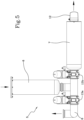
- the homogenisation module 7 comprises an outer body 9, an intermediate body 10 and an inner body 11.
- the outer body 9 has a substantially cylindrical shape extending between a first base wall 9a facing the catalysis module 6 and a second base wall 9b facing an outside environment.
- the inner body 11 has a tubular shape extending at least partially inside the outer body 9 and having a first end 11a coupled to an outlet of the catalysis module 6, to receive the decontamination agent therefrom, and a second end 11b, directed towards the second base wall 9b.
- the intermediate body 10 instead comprises a lateral wall 10a interposed between the inner body 11 and the outer body 9 and a transversal wall 10b interposed between the second end 11b and the second base wall 9b.
- the specific structural shape of the outer 9, intermediate 10 and inner 11 bodies defines an overall conveyance path for the decontamination agent having:
- the transversal wall 10b is constrained and spaced from the second base wall 9b and the latter has a plurality of homogeneously distributed holes 9c through which the decontamination agent is evacuated by the homogenisation module 7 and therefore by the catalyser device 6.
- the evacuation of the decontamination agent from the second base wall 9b can occur directly in the environment outside the machine 1, or in a further conduit which conveys the decontamination agent processed by the catalyser device 5 (and therefore rendered harmless to human health) to a suitable chimney arranged outside the work environment.
- a first sensor 12 is placed downstream of the homogenisation module 7, adapted to measure a concentration of at least one chemical component in the decontamination agent.
- the machine 1 further comprises a second sensor adapted to measure the concentration of at least one chemical component in the decontamination agent positioned inside the processing chamber 2.
- the machine 1 can comprise a third sensor adapted to measure the concentration of at least one chemical component in the decontamination agent positioned downstream of the catalysis module 6 and upstream of the recirculation circuit 8 of the homogenisation module 7, i.e., upstream of the valves 13a and 13b.
- the various sensors can be configured to measure a concentration of hydrogen peroxide in the decontamination agent.
- the first sensor 12 makes it possible to measure the concentration of the chemical components present in the degraded decontamination agent leaving the catalyser device 5, in particular, leaving the homogenisation module 7, during the release into the environment outside the machine 1.
- the first sensor 12 can generate an alert signal (e.g., an acoustic and/or optical signal) to alert an operator that the decontamination agent needs to be subjected to the decomposition process again.
- an alert signal e.g., an acoustic and/or optical signal
- the decontamination agent is passed one or more times through the catalysis module 6, through the recirculation circuit 8, based on the concentration measurement of a certain chemical component inside the processing chamber.
- the machine 1 described herein makes it possible to perform a method for decontaminating surfaces and/or containers in a chamber 2 configured to be hermetically sealed so as to completely isolate its interior with respect to an outside environment (and therefore to the pollutants/pathogens potentially present therein).
- processing chamber 2 Once the processing chamber 2 has been sealed, it is possible to perform one or more processes aimed at decontaminating the materials therein.
- the method specifically involves a decontamination step in which a decontamination agent is injected inside the processing chamber 2, allowed to act and subsequently evacuated through an aeration step.
- a decontamination agent is injected inside the processing chamber 2, allowed to act and subsequently evacuated through an aeration step.
- the processing chamber 2 can be further provided with a glove box to allow not only the decontamination, but also the handling of the components, to be carried out inside the processing chamber 2.
- the decontamination agent is subjected to a decomposition step in which the chemical component is decomposed (for example the aforementioned hydrogen peroxide).
- the decomposition step is performed by conveying the decontamination agent through the catalyser device 5, inside which the agent passes through a succession of catalysis elements 6a in series which promote a decomposition of the chemical compounds which compose it.
- the decomposition step is performed by catalysing a decomposition reaction of the hydrogen peroxide, into water and oxygen.
- the decontamination agent is degraded by its recirculating through the catalysis module 6; this occurs several times until the predefined threshold value is reached, in terms of concentration of the decontaminant, for the discharge of the material inside the chamber 2 or the start of a new handling activity thereof, by means of a glove box.
- a concentration of at least one chemical component of the decontamination agent is measured and if the detected concentration is excessively high (e.g., above a predefined threshold value) the decontamination agent is recirculated to perform a further decomposition step.
- FIG. 4 An embodiment of the catalyser of figure 2 is illustrated in figures 4 , 5 and 6 .
- a decontamination agent is vaporised and injected inside the processing chamber 2 until a concentration, by non-limiting example, of 300 - 2000 ppm (preferably 800 - 1200) is reached, allowed to act for a variable duration of time (based on the selected concentration) and subsequently evacuated through the outlet line 4 and the catalyser 5.
- the system is configured to selectively act on two motorised valves 13a, 13b, placed upstream of the homogenisation module 7 and upstream of the recirculation system 8.
- the two valves 13a, 13b work in an opposite manner, i.e., the opening of one requires the closure of the other.
- the decontaminating agent is degraded through its passage through the catalytic system 5. If the sensor 12 or the middle sensor detects (i.e., the third sensor) concentrations greater than 1ppm, the system enters emergency state, alerting a hazardous situation. In the decontamination step the first valve 13a is closed while the second valve 13b is open allowing the degraded decontaminating agent to pass through the homogenisation module 7.
- the aeration step follows, in which a mixture of air and decontamination agent is circulated inside the catalysis module 6 one or more times, until the desired ppm is reached.
- the decontamination agent begins to recirculate passing through the catalysis module 6 each time until the desired threshold level is reached, detected by a concentration sensor present inside the processing chamber 2 (not shown in the figures).
- the first valve 13a is open while the second valve 13b is closed.
- the homogenisation module 7 supports the abatement of the concentration of decontaminant degraded by the catalysis module 6, by an extension of the exit time thereof from the machine 1, allowing it to further degrade spontaneously.
- a three-way motorised valve can be used.
- the presently claimed machine can be used for degrading a decontamination agent used during a decontamination step of inner surfaces of a decontamination machine 1 and/or containers, preferably containers for pharmaceutical use, comprising one or more passages through a catalysis module 6 and a single exit passage of the degraded decontamination agent through a homogenisation module 7.
- the present invention achieves the proposed objects, overcoming the drawbacks complained of in the prior art by providing the user with a decontamination machine which can operate efficiently, decontaminating surfaces and/or materials which it processes without, however, at the same time generating risks to the health of the operators who use it or of those who are in transit in the work environment in which such a machine is installed.
Landscapes
- Chemical & Material Sciences (AREA)
- Health & Medical Sciences (AREA)
- Chemical Kinetics & Catalysis (AREA)
- Engineering & Computer Science (AREA)
- Veterinary Medicine (AREA)
- Epidemiology (AREA)
- Life Sciences & Earth Sciences (AREA)
- Animal Behavior & Ethology (AREA)
- General Health & Medical Sciences (AREA)
- Public Health (AREA)
- General Chemical & Material Sciences (AREA)
- Organic Chemistry (AREA)
- Materials Engineering (AREA)
- Mechanical Engineering (AREA)
- Apparatus For Disinfection Or Sterilisation (AREA)
- Catalysts (AREA)
Claims (10)
- Maschine zur Dekontaminierung von Oberflächen und/oder Behältern, vorzugsweise von Behältern für pharmazeutische Zwecke, umfassend:- eine Verarbeitungskammer (2), die so konfiguriert ist, dass sie eine Vielzahl von zu dekontaminierenden Behältern enthält, wobei die Kammer (2) während der Durchführung eines Dekontaminationsprozesses hermetisch verschließbar ist;- eine Einlassleitung (3), die so konfiguriert ist, dass sie der Verarbeitungskammer (2) ein Dekontaminationsmittel für die Durchführung des Dekontaminationsprozesses zuführt;- eine Auslassleitung (4), die so konfiguriert ist, dass sie das Dekontaminationsmittel am Ende des Dekontaminationsprozesses aus der Verarbeitungskammer (2) abführt; und- eine Katalysatorvorrichtung (5), die mit der Auslassleitung (4) gekoppelt ist und so konfiguriert ist, dass sie das Dekontaminationsmittel aufnimmt und eine Zersetzung von mindestens einer chemischen Komponente des Dekontaminationsmittels fördert,Dadurch gekennzeichnet, dass sie zudem Folgendes umfasst:- ein Katalysemodul (6), das eine Vielzahl von wechselseitig aneinanderstoßenden Katalyseelementen (6a) umfasst, die in Reihe entlang eines Zufuhrpfades des Dekontaminationsmittels innerhalb des Katalysemoduls (6) angeordnet sind; und- ein Homogenisierungsmodul (7), das stromabwärts des Katalysemoduls (6) in Bezug auf die Zufuhrrichtung des Dekontaminationsmittels angeordnet und so konfiguriert ist, dass es eine Zusammensetzung des Dekontaminationsmittels, das das Katalysemodul (6) verlässt, homogenisiert,Wobei das Homogenisierungsmodul (7) umfasst:- einen Außenkörper (9) mit einer im Wesentlichen zylindrischen Form, der sich zwischen einer ersten, dem Katalysemodul (6) zugewandten Basiswand (9a) und einer zweiten, der äußeren Umgebung zugewandten Basiswand (9b) erstreckt;- einen rohrförmigen Innenkörper (11), der sich zumindest teilweise in das Innere des Außenkörpers (9) erstreckt und ein erstes Ende (11a) aufweist, das mit einem Auslass des Katalysemoduls (6) gekoppelt ist, um das Dekontaminationsmittel aufzunehmen, sowie ein zweites Ende (11b), das zur zweiten Basiswand (9b) gerichtet ist;- einen Zwischenkörper (10), umfassend eine Seitenwand (10a), die zwischen dem Innenkörper (11) und dem Außenkörper (9) angeordnet ist, und einer Querwand (10b), die zwischen dem zweiten Ende (11b) und der zweiten Basiswand (9b) angeordnet ist, um einen Transportpfad für das Dekontaminationsmittel zu definieren, aufweisend:- einen ersten Abschnitt (A), der sich in dem Innenkörper (11) erstreckt;- einen zweiten Abschnitt (B), der sich zwischen dem Innenkörper (11) und dem Zwischenkörper (10) erstreckt;- einen dritten Abschnitt (C), der sich zwischen dem Zwischenkörper (10) und dem Außenkörper (9) erstreckt,Und wobei die Querwand (10b) an die zweite Basiswand (9b) gezwungen und von dieser beabstandet ist, wobei die zweite Basiswand (9b) eine Vielzahl von gleichmäßig verteilten Löchern (9c) aufweist.
- Maschine nach Anspruch 1, wobei die Einlassleitung (3) so konfiguriert ist, dass sie ein Wasserstoffperoxid umfassendes Dekontaminationsmittel zuführt, und die Katalysatorvorrichtung (5) so konfiguriert ist, dass sie das Wasserstoffperoxid zersetzt, vorzugsweise durch Katalysieren der folgenden Reaktion:
2 H2O2 --> 2 H2O + O2
- Maschine nach Anspruch 1, wobei jedes Katalyseelement (6a) einen Rahmen, vorzugsweise einen Metallrahmen, und eine auf den Rahmen aufgebrachte katalytische Beschichtung umfasst, wobei die katalytische Beschichtung vorzugsweise Platin umfasst.
- Maschine nach Anspruch 3, wobei jeder Rahmen eine Wabenstruktur aufweist, die eine Vielzahl von Kanälen für den Durchgang des Dekontaminationsmittels definiert, wobei die zum Rahmen benachbarter Katalyseelemente (6a) gehörenden Kanäle vorzugsweise fluchtend, noch bevorzugter koaxial angeordnet sind.
- Maschine nach einem der vorhergehenden Ansprüche, umfassend einen Rezirkulationskreislauf (8) mit einem ersten Ende, das zwischen dem Katalysemodul (6) und dem Homogenisierungsmodul (7) angeordnet ist, und einem zweiten Ende, das mit der Auslassleitung (4) stromaufwärts des Katalysemoduls (6) gekoppelt werden kann; wobei der Rezirkulationskreislauf (8) selektiv aktivierbar ist, um das Dekontaminationsmittel stromaufwärts des Katalysemoduls (6) zurückzubringen.
- Maschine nach einem der vorhergehenden Ansprüche, umfassend mindestens einen ersten Sensor, der geeignet ist, eine Konzentration mindestens einer chemischen Komponente im Dekontaminationsmittel am Homogenisierungsmodul (7), vorzugsweise stromabwärts des Homogenisierungsmoduls (7), zu messen.
- Maschine nach einem der vorhergehenden Ansprüche, umfassend einen zweiten Sensor, der geeignet ist, eine Konzentration mindestens einer chemischen Komponente im Dekontaminationsmittel am Katalysemodul (6) zu messen.
- Maschine nach Anspruch 7, wobei der zweite Sensor innerhalb der Verarbeitungskammer und/oder in einer Position stromabwärts des Katalysemoduls (6) und stromaufwärts des Rezirkulationskreislaufs und stromaufwärts des Homogenisierungsmoduls (70) angeordnet ist.
- Maschine nach Anspruch 5, 7 oder 8, wobei der mindestens eine Sensor so konfiguriert ist, dass er ein Steuersignal erzeugt, das geeignet ist, den Rezirkulationskreislauf (8) auf der Grundlage der Konzentration der mindestens einen chemischen Komponente im Dekontaminationsmittel zu aktivieren.
- Maschine nach Anspruch 6 oder 7, wobei der mindestens eine Sensor einen Sensor umfasst, der so konfiguriert ist, dass er eine Konzentration von Wasserstoffperoxid im Dekontaminationsmittel misst.
Priority Applications (3)
| Application Number | Priority Date | Filing Date | Title |
|---|---|---|---|
| HRP20250312TT HRP20250312T1 (hr) | 2021-04-01 | 2022-04-01 | Stroj za dekontaminaciju i katalizatorski uređaj za tretman kemijskih para |
| SM20250095T SMT202500095T1 (it) | 2021-04-01 | 2022-04-01 | Macchina per la decontaminazione e dispositivo catalizzatore per il trattamento di vapori chimici |
| RS20250263A RS66717B1 (sr) | 2021-04-01 | 2022-04-01 | Mašina za dekontaminaciju i katalizatorski uređaj za tretman hemijskih isparenja |
Applications Claiming Priority (2)
| Application Number | Priority Date | Filing Date | Title |
|---|---|---|---|
| IT102021000008180A IT202100008180A1 (it) | 2021-04-01 | 2021-04-01 | Macchina per la decontaminazione e dispositivo catalizzatore per il trattamento di vapori chimici |
| PCT/IB2022/053054 WO2022208456A1 (en) | 2021-04-01 | 2022-04-01 | Decontamination machine and catalyser device for the treatment of chemical vapours |
Publications (3)
| Publication Number | Publication Date |
|---|---|
| EP4313178A1 EP4313178A1 (de) | 2024-02-07 |
| EP4313178B1 true EP4313178B1 (de) | 2025-02-12 |
| EP4313178C0 EP4313178C0 (de) | 2025-02-12 |
Family
ID=76708276
Family Applications (1)
| Application Number | Title | Priority Date | Filing Date |
|---|---|---|---|
| EP22718785.3A Active EP4313178B1 (de) | 2021-04-01 | 2022-04-01 | Dekontaminationsmaschine und katalysatorvorrichtung zur behandlung chemischer dämpfe |
Country Status (10)
| Country | Link |
|---|---|
| US (1) | US20240181105A1 (de) |
| EP (1) | EP4313178B1 (de) |
| ES (1) | ES3015657T3 (de) |
| HR (1) | HRP20250312T1 (de) |
| HU (1) | HUE070768T2 (de) |
| IT (1) | IT202100008180A1 (de) |
| PL (1) | PL4313178T3 (de) |
| RS (1) | RS66717B1 (de) |
| SM (1) | SMT202500095T1 (de) |
| WO (1) | WO2022208456A1 (de) |
Family Cites Families (4)
| Publication number | Priority date | Publication date | Assignee | Title |
|---|---|---|---|---|
| US5711705A (en) * | 1995-05-25 | 1998-01-27 | Flanders Filters, Inc. | Isolation work station |
| US7578969B2 (en) * | 2002-08-07 | 2009-08-25 | American Sterilizer Company | Decontamination system for mail and other articles |
| JP5823727B2 (ja) * | 2011-04-28 | 2015-11-25 | パナソニックヘルスケアホールディングス株式会社 | アイソレータ |
| JP7240602B2 (ja) * | 2019-05-13 | 2023-03-16 | ウシオ電機株式会社 | 作業室の無菌環境維持方法、無菌環境維持装置 |
-
2021
- 2021-04-01 IT IT102021000008180A patent/IT202100008180A1/it unknown
-
2022
- 2022-04-01 US US18/553,555 patent/US20240181105A1/en active Pending
- 2022-04-01 RS RS20250263A patent/RS66717B1/sr unknown
- 2022-04-01 EP EP22718785.3A patent/EP4313178B1/de active Active
- 2022-04-01 SM SM20250095T patent/SMT202500095T1/it unknown
- 2022-04-01 PL PL22718785.3T patent/PL4313178T3/pl unknown
- 2022-04-01 HU HUE22718785A patent/HUE070768T2/hu unknown
- 2022-04-01 ES ES22718785T patent/ES3015657T3/es active Active
- 2022-04-01 HR HRP20250312TT patent/HRP20250312T1/hr unknown
- 2022-04-01 WO PCT/IB2022/053054 patent/WO2022208456A1/en not_active Ceased
Also Published As
| Publication number | Publication date |
|---|---|
| RS66717B1 (sr) | 2025-05-30 |
| WO2022208456A1 (en) | 2022-10-06 |
| IT202100008180A1 (it) | 2022-10-01 |
| HUE070768T2 (hu) | 2025-07-28 |
| ES3015657T3 (en) | 2025-05-07 |
| SMT202500095T1 (it) | 2025-05-12 |
| HRP20250312T1 (hr) | 2025-04-25 |
| EP4313178C0 (de) | 2025-02-12 |
| US20240181105A1 (en) | 2024-06-06 |
| PL4313178T3 (pl) | 2025-05-05 |
| EP4313178A1 (de) | 2024-02-07 |
Similar Documents
| Publication | Publication Date | Title |
|---|---|---|
| CA2376117C (en) | Sealed enclosure sterilization | |
| JP3831505B2 (ja) | 医療用滅菌包装における滅菌方法 | |
| US5362443A (en) | Method and apparatus for disposal of medical waste | |
| AU2002356856B2 (en) | Decontamination of critical mail | |
| JP4364800B2 (ja) | 処理容器のための前殺菌を行う前処理チャンバ | |
| CA3011166C (en) | Sterilization device and methods | |
| EP2601977A1 (de) | Wasserstoffperoxid-Dosierungsverfahren | |
| EP0486623A1 (de) | Rückführung sowie dampf- und feuchtigkeitskontrolle in einem abdichtbaren behälter. | |
| US20140301895A1 (en) | In line sterilizer | |
| EP1305105B1 (de) | Vorrichtung zur entfernung eines sterilisierungsmittels aus einer sterilisierungsmittel enthaltenden atmosphäre | |
| CN112469513B (zh) | 用于将无菌的对象从容器无污染地引入到密封防护设施中的组件以及方法 | |
| EP4313178B1 (de) | Dekontaminationsmaschine und katalysatorvorrichtung zur behandlung chemischer dämpfe | |
| US20040022670A1 (en) | System and method for decontaminating and/or sanitizing mail | |
| JP3845110B2 (ja) | 医療用滅菌包装における滅菌方法 | |
| US20220257807A1 (en) | Sterilization unit and methods of using the same | |
| US20230056171A1 (en) | Sterilizing device and method for sterilizing an outer face of a receptacle | |
| CA3045396C (en) | Disinfection and/or sterilization of agricultural crops | |
| CA3164393C (en) | Sterilizing device and method for sterilizing an outer face of a receptacle | |
| CN111479595A (zh) | 菌处理机构以及菌处理方法 | |
| Krebsbach | Keywords Isolator Aseptic Processing Annex 1 Material Transfer Aseptic Transfer Advisor (ATA) Aseptic Transfer Systems For Isolator and RABS Dr. Timo Krebsbach and Dipl.-Ing. Frank Lehmann,· SKAN |
Legal Events
| Date | Code | Title | Description |
|---|---|---|---|
| REG | Reference to a national code |
Ref country code: HR Ref legal event code: TUEP Ref document number: P20250312T Country of ref document: HR |
|
| STAA | Information on the status of an ep patent application or granted ep patent |
Free format text: STATUS: UNKNOWN |
|
| STAA | Information on the status of an ep patent application or granted ep patent |
Free format text: STATUS: THE INTERNATIONAL PUBLICATION HAS BEEN MADE |
|
| PUAI | Public reference made under article 153(3) epc to a published international application that has entered the european phase |
Free format text: ORIGINAL CODE: 0009012 |
|
| STAA | Information on the status of an ep patent application or granted ep patent |
Free format text: STATUS: REQUEST FOR EXAMINATION WAS MADE |
|
| 17P | Request for examination filed |
Effective date: 20231019 |
|
| AK | Designated contracting states |
Kind code of ref document: A1 Designated state(s): AL AT BE BG CH CY CZ DE DK EE ES FI FR GB GR HR HU IE IS IT LI LT LU LV MC MK MT NL NO PL PT RO RS SE SI SK SM TR |
|
| DAV | Request for validation of the european patent (deleted) | ||
| DAX | Request for extension of the european patent (deleted) | ||
| GRAP | Despatch of communication of intention to grant a patent |
Free format text: ORIGINAL CODE: EPIDOSNIGR1 |
|
| STAA | Information on the status of an ep patent application or granted ep patent |
Free format text: STATUS: GRANT OF PATENT IS INTENDED |
|
| INTG | Intention to grant announced |
Effective date: 20241025 |
|
| GRAS | Grant fee paid |
Free format text: ORIGINAL CODE: EPIDOSNIGR3 |
|
| GRAA | (expected) grant |
Free format text: ORIGINAL CODE: 0009210 |
|
| STAA | Information on the status of an ep patent application or granted ep patent |
Free format text: STATUS: THE PATENT HAS BEEN GRANTED |
|
| AK | Designated contracting states |
Kind code of ref document: B1 Designated state(s): AL AT BE BG CH CY CZ DE DK EE ES FI FR GB GR HR HU IE IS IT LI LT LU LV MC MK MT NL NO PL PT RO RS SE SI SK SM TR |
|
| REG | Reference to a national code |
Ref country code: GB Ref legal event code: FG4D |
|
| REG | Reference to a national code |
Ref country code: CH Ref legal event code: EP |
|
| REG | Reference to a national code |
Ref country code: DE Ref legal event code: R096 Ref document number: 602022010532 Country of ref document: DE |
|
| REG | Reference to a national code |
Ref country code: IE Ref legal event code: FG4D |
|
| U01 | Request for unitary effect filed |
Effective date: 20250224 |
|
| U07 | Unitary effect registered |
Designated state(s): AT BE BG DE DK EE FI FR IT LT LU LV MT NL PT RO SE SI Effective date: 20250228 |
|
| REG | Reference to a national code |
Ref country code: HR Ref legal event code: ODRP Ref document number: P20250312T Country of ref document: HR Payment date: 20250318 Year of fee payment: 4 |
|
| REG | Reference to a national code |
Ref country code: SK Ref legal event code: T3 Ref document number: E 46060 Country of ref document: SK |
|
| PGFP | Annual fee paid to national office [announced via postgrant information from national office to epo] |
Ref country code: CZ Payment date: 20250317 Year of fee payment: 4 |
|
| REG | Reference to a national code |
Ref country code: HR Ref legal event code: T1PR Ref document number: P20250312 Country of ref document: HR |
|
| PGFP | Annual fee paid to national office [announced via postgrant information from national office to epo] |
Ref country code: SK Payment date: 20250314 Year of fee payment: 4 |
|
| REG | Reference to a national code |
Ref country code: GR Ref legal event code: EP Ref document number: 20250400551 Country of ref document: GR Effective date: 20250409 |
|
| U20 | Renewal fee for the european patent with unitary effect paid |
Year of fee payment: 4 Effective date: 20250429 |
|
| PGFP | Annual fee paid to national office [announced via postgrant information from national office to epo] |
Ref country code: PL Payment date: 20250325 Year of fee payment: 4 |
|
| PGFP | Annual fee paid to national office [announced via postgrant information from national office to epo] |
Ref country code: ES Payment date: 20250513 Year of fee payment: 4 |
|
| PGFP | Annual fee paid to national office [announced via postgrant information from national office to epo] |
Ref country code: IS Payment date: 20250428 Year of fee payment: 4 Ref country code: HU Payment date: 20250327 Year of fee payment: 4 Ref country code: NO Payment date: 20250422 Year of fee payment: 4 |
|
| PGFP | Annual fee paid to national office [announced via postgrant information from national office to epo] |
Ref country code: AL Payment date: 20250429 Year of fee payment: 4 |
|
| PGFP | Annual fee paid to national office [announced via postgrant information from national office to epo] |
Ref country code: GR Payment date: 20250422 Year of fee payment: 4 |
|
| PGFP | Annual fee paid to national office [announced via postgrant information from national office to epo] |
Ref country code: CH Payment date: 20250501 Year of fee payment: 4 |
|
| REG | Reference to a national code |
Ref country code: HU Ref legal event code: AG4A Ref document number: E070768 Country of ref document: HU |
|
| PGFP | Annual fee paid to national office [announced via postgrant information from national office to epo] |
Ref country code: IE Payment date: 20250417 Year of fee payment: 4 |
|
| PGFP | Annual fee paid to national office [announced via postgrant information from national office to epo] |
Ref country code: MK Payment date: 20250314 Year of fee payment: 4 |
|
| PLBE | No opposition filed within time limit |
Free format text: ORIGINAL CODE: 0009261 |
|
| STAA | Information on the status of an ep patent application or granted ep patent |
Free format text: STATUS: NO OPPOSITION FILED WITHIN TIME LIMIT |
|
| PGFP | Annual fee paid to national office [announced via postgrant information from national office to epo] |
Ref country code: CY Payment date: 20250318 Year of fee payment: 4 |
|
| 26N | No opposition filed |
Effective date: 20251113 |
|
| PGFP | Annual fee paid to national office [announced via postgrant information from national office to epo] |
Ref country code: SM Payment date: 20260220 Year of fee payment: 5 |
|
| PGFP | Annual fee paid to national office [announced via postgrant information from national office to epo] |
Ref country code: GB Payment date: 20260304 Year of fee payment: 5 |
|
| PGFP | Annual fee paid to national office [announced via postgrant information from national office to epo] |
Ref country code: MC Payment date: 20260326 Year of fee payment: 5 |
|
| REG | Reference to a national code |
Ref country code: HR Ref legal event code: ODRP Ref document number: P20250312 Country of ref document: HR Payment date: 20260311 Year of fee payment: 5 |
|
| PGFP | Annual fee paid to national office [announced via postgrant information from national office to epo] |
Ref country code: HR Payment date: 20260311 Year of fee payment: 5 |
|
| PGFP | Annual fee paid to national office [announced via postgrant information from national office to epo] |
Ref country code: RS Payment date: 20260311 Year of fee payment: 5 |
|
| PGFP | Annual fee paid to national office [announced via postgrant information from national office to epo] |
Ref country code: TR Payment date: 20260313 Year of fee payment: 5 |