EP4313520B1 - Dispositif de préhension à coulisseau réglable - Google Patents
Dispositif de préhension à coulisseau réglable Download PDFInfo
- Publication number
- EP4313520B1 EP4313520B1 EP22715516.5A EP22715516A EP4313520B1 EP 4313520 B1 EP4313520 B1 EP 4313520B1 EP 22715516 A EP22715516 A EP 22715516A EP 4313520 B1 EP4313520 B1 EP 4313520B1
- Authority
- EP
- European Patent Office
- Prior art keywords
- slide
- adjustment
- transverse
- slides
- gripping device
- Prior art date
- Legal status (The legal status is an assumption and is not a legal conclusion. Google has not performed a legal analysis and makes no representation as to the accuracy of the status listed.)
- Active
Links
Images


Classifications
-
- B—PERFORMING OPERATIONS; TRANSPORTING
- B25—HAND TOOLS; PORTABLE POWER-DRIVEN TOOLS; MANIPULATORS
- B25J—MANIPULATORS; CHAMBERS PROVIDED WITH MANIPULATION DEVICES
- B25J15/00—Gripping heads and other end effectors
- B25J15/0052—Gripping heads and other end effectors multiple gripper units or multiple end effectors
- B25J15/0061—Gripping heads and other end effectors multiple gripper units or multiple end effectors mounted on a modular gripping structure
-
- B—PERFORMING OPERATIONS; TRANSPORTING
- B25—HAND TOOLS; PORTABLE POWER-DRIVEN TOOLS; MANIPULATORS
- B25J—MANIPULATORS; CHAMBERS PROVIDED WITH MANIPULATION DEVICES
- B25J15/00—Gripping heads and other end effectors
- B25J15/06—Gripping heads and other end effectors with vacuum or magnetic holding means
- B25J15/0616—Gripping heads and other end effectors with vacuum or magnetic holding means with vacuum
-
- B—PERFORMING OPERATIONS; TRANSPORTING
- B25—HAND TOOLS; PORTABLE POWER-DRIVEN TOOLS; MANIPULATORS
- B25J—MANIPULATORS; CHAMBERS PROVIDED WITH MANIPULATION DEVICES
- B25J19/00—Accessories fitted to manipulators, e.g. for monitoring, for viewing; Safety devices combined with or specially adapted for use in connection with manipulators
- B25J19/0025—Means for supplying energy to the end effector
-
- B—PERFORMING OPERATIONS; TRANSPORTING
- B65—CONVEYING; PACKING; STORING; HANDLING THIN OR FILAMENTARY MATERIAL
- B65G—TRANSPORT OR STORAGE DEVICES, e.g. CONVEYORS FOR LOADING OR TIPPING, SHOP CONVEYOR SYSTEMS OR PNEUMATIC TUBE CONVEYORS
- B65G47/00—Article or material-handling devices associated with conveyors; Methods employing such devices
- B65G47/74—Feeding, transfer, or discharging devices of particular kinds or types
- B65G47/90—Devices for picking-up and depositing articles or materials
- B65G47/91—Devices for picking-up and depositing articles or materials incorporating pneumatic, e.g. suction, grippers
- B65G47/918—Devices for picking-up and depositing articles or materials incorporating pneumatic, e.g. suction, grippers with at least two picking-up heads
-
- B—PERFORMING OPERATIONS; TRANSPORTING
- B66—HOISTING; LIFTING; HAULING
- B66C—CRANES; LOAD-ENGAGING ELEMENTS OR DEVICES FOR CRANES, CAPSTANS, WINCHES, OR TACKLES
- B66C1/00—Load-engaging elements or devices attached to lifting or lowering gear of cranes or adapted for connection therewith for transmitting lifting forces to articles or groups of articles
- B66C1/02—Load-engaging elements or devices attached to lifting or lowering gear of cranes or adapted for connection therewith for transmitting lifting forces to articles or groups of articles by suction means
- B66C1/0237—Multiple lifting units; More than one suction area
- B66C1/0243—Separate cups
Definitions
- the invention relates to an adjustable gripping device and a manipulator with an adjustable gripping device.
- Adjustable or adjustable gripping devices are known from the prior art, which are intended to enable the position adjustment of holding devices, in particular vacuum-operated holding devices.
- the position adjustment of the holding devices is intended to enable the manipulation of workpieces of different sizes.
- EP 3031586 A1 An adjustable gripping device has become known. It comprises stationary arms with guide rails and several cross arms that can be moved along the guide rails, with movable holding means arranged on the movable cross arms.
- EP 1041295 B1 discloses a support device with profiled rods, which rods are detachably connected to each other via movable clamping pieces.
- EP 1871696 B1 which originates from the applicant, shows a gripping device for a manipulator with several support arms rotatable about an axis.
- the support arms comprise a base arm and a cantilever arm, on each of which holding means are positioned.
- US 6796588 B2 discloses a suction device with telescopic evacuation tubes, comprising a boom and a plurality of sliders which are movable along the boom.
- the object of the present invention was to provide means by which workpieces, in particular plate-shaped workpieces or sheet metal components, of various sizes and shapes can be manipulated with a single, flexible, easy, and precisely adjustable gripping device.
- the gripping device should be both robust and stable. be designed, structurally simple, compact, durable and safe to handle.
- the invention relates to a gripping device designed to pick up and release a preferably plate-shaped workpiece to be transported.
- the gripping device comprises a support platform with a bottom side and an upper side opposite the bottom side.
- the support platform is formed on its top side with a connection interface designed to couple the gripping device to a manipulator.
- the support platform is also formed on its bottom side with at least two adjustment slide guides.
- the gripping device also comprises a plurality of holding means for holding the workpiece.
- the holding means are coupled to the support platform, whereby coupling can be direct or indirect. Furthermore, the coupling can preferably be detachable, particularly preferably detachable without tools.
- the holding means each have contact sides, which contact sides face away from the underside of the support platform and which span a common contact plane.
- Various types of holding means are familiar to those skilled in the art, which is why they will not be discussed in detail here.
- the holding means can be suction cup-like, vacuum-actuated holding means.
- magnetically acting holding means are also conceivable, whereby both pressure-actuated permanent magnets and holding means with electromagnets can be used.
- the gripping device also includes supply means designed to activate and deactivate the holding means.
- the supply means can be, for example, components of a vacuum supply (such as a power pack, flexible vacuum hoses, rigid vacuum pipes, valves, valve shutoffs, valve terminals, etc.) or components of a power supply (such as a power pack, electrical cables, etc.).
- the gripping device further comprises at least two displaceable adjustment slides. These adjustment slides are each at least partially received or held in at least one of the adjustment slide guides of the support platform. Furthermore, the adjustment slides are displaceable in these adjustment slide guides relative to the support platform along a first direction. The first direction is also referred to below as the X-direction. At least one of the adjustment slides is formed with at least one transverse guide.
- the gripping device also comprises at least one cross slide, on which at least one of the holding means is arranged. The cross slide is at least partially received or held in the transverse guide and is displaceable in the transverse guide relative to the adjustment slide along a second direction. The second direction is also referred to below as the Y-direction.
- the first direction and the second direction are orthogonal to one another. Preferably, the first and the second directions run parallel to the contact plane, wherein the contact plane can run parallel to the X-Y plane.
- a guide section of the at least one cross slide which is received or held in the at least one transverse guide, is profile-shaped, in particular hollow-profile-shaped.
- This guide section can be linearly extended or retracted in the transverse guide.
- the profile-shaped guide section of the at least one cross slide can be circular, rectangular, or oval, for example. In principle, a dovetail-shaped cross section may also be appropriate.
- the holding means can be positioned on the cross guide(s), but also on the adjustment slides, or directly on the support platform.
- the actual positioning, as well as the size and number of the holding means, are generally at the discretion of the expert.
- the holding means positioned on the extendable cross slides are particularly characterized by their ability to move in two dimensions, i.e., in the X and Y directions.
- individual adhesive means can be activated and deactivated individually and independently of one another as needed.
- a manually or automatically actuated shut-off valve can be provided, for example, in a supply line of the respective holding means.
- the at least two adjustment slides and the at least one cross slide can be moved manually by an operator.
- an automatic, in particular Pneumatic or electrical displacement or adjustment of the slides is conceivable.
- Displacement and adjustment parameters can preferably be provided to an operator using a software-based setup plan.
- both the adjustment slide guide and the at least one transverse guide can be designed as linear guides. Such a design is both cost-effective to manufacture and easy to operate, yet does not compromise freedom of movement due to the ability of the holding means to be displaced in two directions.
- the gripping device designed according to the invention is both structurally simple and therefore cost-effective, as well as robust and therefore durable and requiring little repair. Furthermore, the gripping device can be collapsed particularly compactly, and the distance between the individual holding means can therefore be adjusted to an extremely small distance. This is particularly the case when the at least one linearly extendable cross guide is fully retracted. Such an adjustment can be particularly advantageous for very small workpieces or for angled or folded workpieces.
- the extendability of the at least one cross slide allows the holding means to be spaced far apart from one another.
- the flexible displacement and adjustability can also prevent or at least largely mitigate the risk of collisions with the manipulator, but also with peripheral objects.
- Moving the slides along the guides is easy and quick. This allows the gripping device, or rather the holding devices positioned on the gripping device, to be flexibly adapted to the specific geometry of the workpiece to be manipulated.
- a wide range of workpiece dimensions can be manipulated using just a single, yet flexibly adjustable gripping device. Because the adjustment is particularly simple and can therefore be performed even by less well-trained setup personnel, setup times can be significantly reduced. This can have positive economic effects, especially when the number of workpieces to be manipulated is small.
- At least one of the adjustment slides is designed with two parallel transverse guides, and if in each transverse guide a extendable cross slide is received or held, with at least one of the holding means being arranged on each cross slide.
- the holding means are formed on mutually opposite end sections of the two cross slides. When both cross slides are extended, the respective holding means are not only further distanced from the adjustment slide, but the distance between the two holding means is also increased. In this way, the greatest possible extension distance can be achieved in a simple manner.
- the two cross slides thus represent a bilateral extension option for the adjustment slide along the second direction, which allows for even more flexible adjustability. If the holding means are arranged on the end sections of the respective cross slides, the smallest possible projection can be achieved in the inserted state and the greatest possible projection can be achieved in the fully extended state.
- the surface spanned by the suction cups does not create any additional interference contours. This can be advantageous for moving the gripping device close to a machine, in particular to a bending tool of a bending machine. For example, with box-shaped components where the base does not extend beyond the smallest possible gripper setting, no repositioning may be necessary.
- a transverse axis oriented along the first direction lies equidistant between the two mutually parallel transverse guides.
- the holding means arranged on the two cross slides are positioned such that the holding means lie with their respective holding means center on the transverse axis.
- the opposing holding means according to this development are inclined towards each other when viewed from the underside of the support platform such that their holding means center points lie on the transverse axis.
- the holding means are relative to the respective The guide section is positioned offset. This further improves the accuracy of the adjustment, as any misalignment or offset errors caused by the parallel arrangement of the two cross guides or the two cross slides can be compensated.
- the adjustment slides are each designed with an adjustment slide fixing device.
- These adjustment slide fixing devices can be operated independently of one another and are designed to releasably fix the adjustment slides relative to the support platform as needed.
- the adjustment slides are each designed with at least one cross slide fixing device.
- This cross slide fixing device is designed to releasably fix the at least one cross slide relative to the adjustment slide as needed.
- the fixing devices can be operated manually or at least with minimal tool use.
- Another advantageous embodiment is one in which at least one first scale is formed on the support platform along the first direction. If necessary, a plurality of first scales can also be provided on the support platform. Alternatively or additionally, it can also be advantageous if a second scale is formed on at least one cross slide, in particular on its guide section, along the second direction. With the aid of the scale markings, a user can carry out settings or adjustments on the gripping device quickly, easily and correctly. The respective current setting or position of the adjustment slides and of the at least one cross slide can be easily read off the two scales using an indicator. In particular, if a plurality of first scales are provided, it can be advantageous if these are scaled offset by one adjustment slide width, thereby ensuring precise adjustability.
- the first scale and the second scale are arranged parallel to the contact plane so that they are visible when viewing the underside of the support platform. This can make it considerably easier for the user to read the current or new setting position of the adjustment slides, as well as of at least one cross slide. The user does not have to laboriously turn or move during adjustment work to read the scales, but can see all setting parameters when viewing the underside of the support platform. Furthermore, it is also possible for all locking recesses or locking holes to be visible when viewing the underside. However, it is also possible for only the locking recesses in the support platform to be visible when viewing the underside of the support platform and for the locking recesses of the cross slide to be orthogonal to the contact plane. The locking recesses of the cross slide would therefore only be visible to the observer when viewing the gripping device from the side. The exact arrangement of the locking recesses depends on the locking mechanism and is at the discretion of the expert.
- the adjustment slide fixing device can be designed as an adjustment slide locking device, and/or for the cross slide fixing device to be designed as a cross slide locking device.
- the support platform can be designed with a plurality of locking recesses that are equidistantly spaced from one another along the first direction.
- the locking recesses are preferably formed in the guide section of the cross slide.
- a locking element of the adjustment slide locking device can be engageable with the locking recesses of the support platform.
- the cross slide can be designed with a plurality of locking recesses that are equidistantly spaced from one another along the second direction, and a locking element of the cross slide locking device can be engageable with the locking recesses of the cross slide.
- the scale markings of the first and second scales preferably correspond to the distances between the respective equidistantly spaced or discrete locking recesses. This allows the user to perform settings and adjustments on the gripping device quickly, easily, and accurately.
- the current setting or position of the adjustment slides and at least one cross slide can be easily read off using an indicator on the two scales.
- the locking recesses and the respective scales are conveniently arranged next to each other, allowing the current setting to be read off easily and precisely without the need for additional tools.
- stepless adjustment without equidistant locking recesses is also conceivable.
- the locking element of the adjustment slide locking device and/or the locking element of the cross slide locking device can be designed as a bolt, which bolt can be engaged with the locking recesses of the support platform and/or with the locking recesses of the cross slide.
- bolt is to be interpreted purely functionally and is not intended to be structurally restrictive. It encompasses any pin-shaped actuating means extending along an axis.
- a bolt does not necessarily have to have a circular cross-section, but can also be oval or rectangular, for example.
- a type of plate-shaped knob or T-shaped handle can be formed on the user-side end of the bolt so that a user can actuate the bolt quickly and safely.
- the bolt can be engageable with the locking recesses, preferably in a form-fitting and/or force-fitting manner. As soon as the bolt is engaged with a recess, any relative movement or displacement is prevented.
- the bolt is manually operable and if the bolt is designed with a spring-loaded operating mechanism, wherein preferably a spring element is engaged with one of the locking recesses in its rest state by means of a spring force acting in the axial direction of the bolt.
- the bolt is in a locked position in its rest state and can be pulled out of or moved out of the respective locking recess by a user by pulling along a fixing axis of the bolt against the spring force.
- Adjustment of the adjustment slide or the cross slide is preferably carried out with two hands. With one hand, the operator pulls the bolt from its rest position, i.e. out of the locking recess of the current adjustment position, and moves the adjustment slide or the cross slide into the new adjustment position.
- the operator can preferably read off the scales when the adjustment position has been reached. Once the new setting position is reached, the operator releases the bolt or locking element, causing the spring to automatically return to its rest position and move the bolt into the new locking recess, where it engages. The user may also need to press the bolt into the locking recess to secure it. This prevents any unintentional shifting or relative movement of the adjustment slides or cross slide.
- the locking recesses of the support platform and/or the locking recesses of the cross slide are designed as locking holes, wherein the bolt can be brought into engagement with the locking holes at least largely in a complementary manner.
- the locking recesses of the support platform and/or the locking recesses of the cross slide are formed by a rack with tooth gaps, wherein the bolt can be brought into engagement with the tooth gaps in a manner that is at least largely complementary in shape. Furthermore, by engaging the bolt in the tooth gaps, a fixation by frictional engagement can be achieved, which can make the fixation even more secure.
- a design of the guide section of the cross slide as a rack is particularly expedient here.
- the adjustment slide fixing device can comprise at least one screw, wherein a clamping force can be applied between one of the adjustment slides and the support platform by means of the screw.
- the cross slide fixing device can comprise at least one screw, wherein a clamping force can be applied between the at least one cross slide and one of the adjustment slides by means of the screw.
- An adjustment slide fixing device or cross slide fixing device acting with one or more screw connections can be particularly stable and ensure high strength. This can, among other things, reduce the risk of unintentional loosening and the associated accidents.
- the adjustment slide fixing device may comprise at least one clamping lever, eccentric lever, or tensioning lever, wherein a clamping force can be applied between one of the adjustment slides and the support platform by means of the clamping lever, eccentric lever, or tensioning lever.
- the cross slide fixing device comprises at least one clamping lever, eccentric lever, or tensioning lever, wherein a clamping force can be applied between the at least one cross slide and one of the adjustment slides by means of the clamping lever, eccentric lever, or tensioning lever.
- the clamping lever, eccentric lever, or tensioning lever may also be combined with a screw.
- the adjustment slide fixing device and/or the cross slide fixing device can comprise a pneumatic fixing device and thus be pneumatically fixable.
- a pneumatic fixing device By providing a pneumatic fixing device, fixing can be carried out more quickly and, if necessary, also with extreme precision and reliability. Furthermore, a high degree of safety can be ensured by means of pneumatic fixing of the slides. It is also possible for the at least two adjustment slides and the at least one cross slide to not only be pneumatically fixable but also to be automatically pneumatically displaceable.
- the adjustment slide guides are designed as prism tracks for positive engagement with sections of the adjustment slides.
- the adjustment slide guides are preferably designed as prism tracks for positive engagement with sections of both adjustment slides.
- section here means that not the entire adjustment slide is received or held in the adjustment slide guides, but only a part of it. This part or section can be, for example, a type of sliding block.
- each adjustment slide has two such sections or sliding blocks, with each sliding block being guided in one of the adjustment slide guides. This can ensure particularly good stability and precise guidance or displacement. Because the two adjustment slide guides function as rails, so to speak, smooth running is guaranteed. This is particularly true when the adjustment slides are particularly long, i.e., extend longitudinally along the second direction.
- the guide section of the at least one cross slide is formed, at least in sections, with a hollow profile, which hollow profile is designed as a vacuum channel.
- the vacuum channel is fluidly connected to the supply means and to the at least one holding means arranged on the cross slide.
- the supply means can comprise a vacuum supply module, a valve island, and preferably flexible or hose-like vacuum lines.
- the valve island can advantageously be arranged on the upper side of the support platform.
- the guide section of the at least one cross slide is designed as a hollow profile.
- Such a hollow profile can define a channel, in particular a vacuum channel, wherein a vacuum pipe can be arranged in the vacuum channel.
- the vacuum channel can extend longitudinally in the hollow profile along the second direction and be fluidly connected to the holding means arranged on the cross slide.
- the holding means is expediently designed here as a vacuum holding means.
- the vacuum pipe preferably extends longitudinally in one of the adjustment slides along the second direction.
- the vacuum pipe is positioned displaceably in the vacuum channel along the second direction.
- the vacuum supply module is fluidly connected to the holding means(s) via the valve island by means of the vacuum lines and the vacuum pipe.
- At least one spiral supply line can be formed, which is provided for applying negative pressure to at least one of the holding means.
- the at least one spiral supply line can be arranged on the underside of the support platform and aligned along the first direction. It has also proven advantageous if the guide section of the at least one cross slide passes through at least some of the at least one spiral supply line.
- the respective guide sections can serve as carriers for the supply, for example, of negative pressure for activating and deactivating the holding means.
- the spiral shape enables the adjustment or extension and insertion of the adjustment and cross slides without additional aids or additional structural components.
- the supply means can comprise a valve island, which valve island is fluidly connected to the holding means by means of shut-off valves.
- the valve island can advantageously be arranged on the upper side of the support platform.
- the individual valves of the valve island can each be fluidly connected to one or, if necessary, several of the holding means.
- the holding means(s) can expediently be designed as vacuum holding means.
- the vacuum supply module is fluidly connected to the holding means(s) via the valve island. It can be particularly advantageous if the holding means can be activated and deactivated as needed using their associated valves on the valve island. Such an individual holding means shutdown can further expand the usage and adjustment options of the gripping device.
- the valves arranged on the valve island can, for example, be mechanically acting or designed with a spring return mechanism.
- the valves can preferably be supplied with current separately and can be activated and deactivated by means of a controller.
- Such a design can be particularly safe in operation, especially because a possible power failure - in contrast to spring-return valves - is uncritical and does not lead to an unintentional release of a workpiece from the holding devices.
- a further adjustment carriage is formed, which comprises a first and a second guide bar.
- the two guide bars are displaceable along the first direction.
- the adjustment carriage can be extended linearly relative to the support platform along the first direction by means of the guide bars.
- the guide bars are preferably guided through openings on an end face of the support platform or through prism or profile tracks in the support platform.
- the guide bars are arranged on the upper side of the support platform or are guided in guide means positioned on the upper side of the support platform.
- a further first scale is also formed on one or both of the guide bars, i.e.
- the further adjustment carriage is expediently designed to be at least largely identical in construction to the first and second adjustment carriage.
- the guide bars of the further adjustment slide are offset from each other in such a way are such that they do not interfere with each other and, in particular, do not form an undesirable additional interference contour when retracted or pushed in.
- At least one further cross slide is formed, on which cross slide at least one of the holding means is arranged, and which cross slide is at least partially received or held in a transverse guide of the further adjustment slide.
- the cross slide is displaceable in the transverse guide relative to the adjustment slide along the second direction, wherein a guide section of the further adjustment slide received or held in the at least one transverse guide is profile-shaped, in particular hollow-profile-shaped, and wherein this guide section can be linearly extended in the transverse guide or can also be linearly inserted again.
- all adjustment slides and all cross slides of the gripping device received or held in the adjustment slide and which can be extended are of the same construction or at least largely of the same construction. This reduces storage costs and sometimes considerably simplifies any maintenance and repair work.
- a vacuum pipe that can be linearly extended relative to the support platform, parallel to the guide beams, which vacuum pipe is fluidly connected to the supply means and to the at least one holding means arranged on the further adjustment slide.
- the supply means can also comprise a further vacuum pipe that is arranged in a further vacuum channel in the preferably hollow-profile-shaped guide beam.
- the further vacuum pipe can be arranged in the support platform and parallel to the guide beams.
- the further vacuum pipe is preferably positioned between the guide beams when viewing the support platform from the underside.
- the further vacuum pipe is arranged on the further adjustment slide, wherein the holding means arranged on the further cross slide is fluidly connected to a valve terminal or a vacuum supply module by means of a preferably flexible vacuum line and by means of the further vacuum pipe.
- the at least one spiral supply line is penetrated at least partially by at least one of the guide bars of the adjustment slides, or that the at least one spiral supply line is arranged between the two guide bars.
- At least one energy chain is mounted so as to be movable along the first direction, which energy chain is designed to move the adjustment slides and/or to move the guide beams, and that at least one preferably flexible or hose-shaped vacuum line is guided in the energy chain.
- energy chains are also known in the specialist world as energy guide chains, E-chains or drag chains. Such an arrangement can be moved particularly precisely and, moreover, can be constructed in a comparatively space-saving manner. Furthermore, a spiral-shaped supply line is well protected from damage by this design.
- the object of the invention is also achieved by a manipulator designed to pick up and release a preferably plate-shaped workpiece to be transported.
- the manipulator comprises a gripping device designed according to one of the claims.
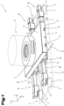
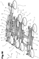
- the Fig. 1 to 5 show a gripping device 1 for manipulating, i.e., for transporting, or for picking up and delivering, transferring, or depositing, preferably plate-shaped workpieces 2 during their processing with a processing machine.
- the gripping device 1 comprises, as a central element, a support platform 4 for the holding means 3 with a connection interface 5 by means of which the gripping device 1 can be attached to an articulated arm 6, for example of a manipulator, in particular an articulated-arm robot.
- the holding means 3 are connected to the support platform 4 in such a way that they are adjustable relative to the support platform 4.
- the support platform 4 has a bottom side 17 and a top side 41 opposite the bottom side 17.
- the connection interface 5 is formed on the top side 41 of the support platform 4 and for coupling the gripping device 1 to a manipulator.
- the connection interface 5 can be any known type of coupling means.
- a screw or bayonet connection can be provided, but flange connections are also conceivable.
- the gripping device 1 can also be fixedly arranged, i.e., permanently or irremovably, on a manipulator.
- the gripping device 1 has several holding means 3 for direct contact or direct attachment to the workpiece 2.
- the workpiece 2 is in the Fig. 1 shown schematically by means of dashed lines as an example of a sheet metal workpiece.
- the holding means 3 can be Fig. 1 to 5 supply means 27 (not shown for the sake of simplicity) can be activated or deactivated as required, whereby the workpiece 2 can be picked up or put down again.
- the holding means 3 are coupled to the support platform 4 and have contact sides 7, which contact sides 7 face away from the underside 17 of the support platform 4 and which contact sides 7 span or define a common flat contact plane 8.
- the holding means 3 shown are vacuum holding means, each of which has a suction cup with a contact side 7 for contacting a workpiece 2. A workpiece 2 picked up by activating the holding means 3 can thus be fed to a processing area of the processing machine.
- the positions of the holding means 3 can be changed such that they correspond at least largely to the shape or extent of the workpiece 2 or the surface of the workpiece 2 to be gripped. This means that for a small workpiece 2, smaller relative distances between the holding means 3 are possible, while for larger workpieces 2, correspondingly larger relative distances are set.
- the gripping device 1 has at least one first adjustment carriage 9 and a second adjustment carriage 10.
- the two adjustment carriages 9, 10 are each movable along a first direction 13 on an adjustment carriage guide 11, 12 formed between the adjustment carriages 9, 10 and the support platform 4.
- the at least two adjustment carriage guides 11, 12 are formed for this purpose on the underside 17 of the support platform 4.
- the at least two adjustment carriages 9, 10 are each at least partially received in at least one of the adjustment carriage guides 11, 12 and are displaceable in the adjustment carriage guides 11, 12 relative to the support platform 4 along a first direction 13.
- At least one of the adjustment carriages 9, 10 is formed with at least one transverse guide 15. In the Fig. 1 to 5
- Both adjustment slides 9, 10 are each provided with two parallel transverse guides 15.
- cross slides 14 are shown, on each of which at least one of the holding means 3 is arranged.
- a single holding means 3 is positioned at the end section of each cross slide 14.
- the cross slides 14 are at least partially received in the respective cross guide 15.
- the cross slides 14 are displaceable, or traversable and adjustable, in these cross guides 15 relative to the respective adjustment slide 9, 10 along a second direction 16.
- the first direction 13 and the second direction 16 are orthogonal to each other. In the figures, the first direction 13 is aligned along the X-axis and the second direction 16 along the Y-axis.
- the cross slides 14 shown are each formed with a guide section 42.
- the respective guide sections 42 are each received in one of the cross guides 15 or are displaceably guided therein and are profile-shaped, in particular hollow profile-shaped.
- the guide sections 42 can be linearly extended and linearly retracted into the cross guides 15.
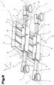
- the Fig. 2 shows the gripping device 1 according to Fig. 1 in perspective view with a view from below, i.e. with a view towards the underside 17 of the support platform 4.
- the Fig. 3 shows the gripping device 1 according to the Fig. 1 and 2 in a view from below, i.e. also looking towards the underside 17 of the carrying platform 4.
- the adjustment slides 9, 10 are each formed with two mutually parallel transverse guides 15, wherein an extendable transverse slide 14 is received in each transverse guide 15.
- At least one of the holding means 3 is arranged on each transverse slide 14, wherein the holding means 3 are formed on mutually opposite end sections of the two transverse slides 14.
- Further holding means 3 could also be positioned directly and thus non-displaceably on the support platform 4.
- further holding means 3 it would also be conceivable for further holding means 3 to be positioned directly and thus displaceably along the first direction 13 on one or both of the adjustment slides 9, 10.
- these developments are not shown in the figures.
- a transverse axis 43 oriented along the first direction 13 can be located equidistant between the two parallel transverse guides 15.
- Holding means 3 arranged on the two cross slides 14 can be positioned such that they lie with their respective holding means center point 44 on the transverse axis 43. This is particularly clear in the Fig. 3 visualized.
- the adjustment slides 9, 10 can each be designed with an adjustment slide fixing device in the form of an adjustment slide locking device 18, which can be actuated independently of one another and can be designed for the required releasable fixing of the adjustment slides 9, 10 relative to the support platform 4.
- the adjustment slides 9, 10 can be designed with one or more cross slide fixing devices in the form of cross slide locking devices 22, which can be designed for the required releasable fixing of the at least one cross slide 14 relative to the adjustment slide 9, 10. Particularly in the Fig. 2 to 5 the locking devices 18, 22 are illustrated. If the adjustment slides 9, 10 are each designed with two cross slides 14, it is possible that these two cross slides 14 can be fixed simultaneously, or jointly, with a single cross slide locking device 22. However, it is also possible that each cross slide 14, as in the Fig. 3 shown, has its own cross slide locking device 22.
- At least one first scale 21 can be formed on the support platform 4 along the first direction 13.
- the support platform 4 can also be formed with a plurality of locking recesses that are equidistantly spaced from one another along the first direction 13 and arranged one behind the other along the first direction 13.
- the scale 21 and the locking recesses correlating with the scale 21 are arranged next to one another. Graduations of the scale 21 correspond to the positions of the locking holes 20. This makes it easier for a user to set the desired X-position for the holding elements 3 along the first direction 13. This is particularly true in the Fig. 2 and 3 clearly visible.
- two differently labeled scales 21 are mounted, which are offset from each other by one adjustment slide width.
- Direction indicators 46 facilitate correct scale setting for the user. This is particularly useful when the user is given the required setting parameters by a computer program.
- the scales 21 can start from a zero value, but can also, as shown in the Fig. 3 As can be seen, extend from a negative starting value to a positive final value.
- the two adjustment slides 9, 10 are movable in the first direction 13 by means of adjustment slide guides 11, 12 designed as linear guides on the underside 17 of the support platform 4.
- the adjustment slide guides 11, 12 comprise prism tracks for positive engagement with Sections of the two adjustment slides 9, 10.
- these could also be formed, for example, by dovetail guides.
- the sections that engage with the adjustment slide guides 11, 12 can be, for example, sliding blocks, but also rolling elements.
- a locking element of the adjustment slide locking device 18 can be brought into engagement with the locking recesses of the support platform 4.
- a second scale 23 can be formed on the cross slide 14 along the second direction 16.
- the cross slides 14 can be formed with a plurality of locking recesses equidistant from one another along the second direction 16, wherein a locking element of the cross slide locking device 22 can be brought into engagement with the locking recesses of the cross slide 14.
- These locking recesses are arranged on the respective guide sections 42 of the cross slides 14 and, in particular, as shown in the Fig. 2
- the locking recesses of the support platform 4 and the locking recesses of the cross slide 14 can each be designed as locking holes 20, 24.
- the first scale 21 and the second scale 23 can, as in the Fig. 2 and 3 recognizable, be arranged parallel to the contact plane 8 so that they are visible when looking at the underside 17 of the support platform 4.
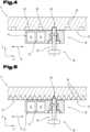
- FIGs. 4 and 5 A conceivable functional mechanism of a locking device 18, 22 is illustrated using adjustment slide locking devices 18.
- the locking mechanism shown can be used not only for an adjustment slide locking device 18, but also for a cross slide locking device 22.
- the Figs. 4 and 5 each show a section through the gripping device 1. The cutting positions are shown in the Fig. 3 marked by Roman numerals.
- the Figs. 4 and 5 The locking element of the adjustment slide locking device 18 shown can be designed as a bolt 19. This bolt 19 can be brought into engagement with the locking recesses of the support platform 4.
- a locking device 22 and a scale 23 are also provided for positioning the cross slides 14 on the respective adjustment slides 9, 10. Accordingly, in the activated position, the locking devices 22 engage in locking holes 24 which are provided on the Cross slide 14 are formed ( Fig. 2 ). The locking holes 24 of the cross slides 14 are arranged equidistantly from one another along the second direction 16 Y-direction. With the aid of the locking devices 22, the cross slides 14 can be fixed in a corresponding number of locking positions on the respective adjustment slides 9, 10. The functioning of this second locking device 22 for positioning the cross slides 14 on the respective adjustment slides 9, 10 can be described in the same way as already described above with reference to the Figs. 4 and 5 for the adjustment slide locking devices 18 has been described.
- the locking device 18 can comprise a bolt 19 which is spring-loaded in the axial direction and is mounted in the adjustment slide 10. An end of the bolt 19 facing the underside 17 of the support platform 4 extends into one of a row of locking holes 20 formed in the support platform 4. The bolt 19 thus forms a lock by means of which the adjustment slide 10 is fixed to the support platform 4 against displacement along the first direction 13.
- the adjustment slide locking device 18 is in its activated or locked position. To adjust the adjustment slide 10 and thus the holding elements 3 connected to it, the adjustment slide locking device 18 can be deactivated by a user pulling the bolt 19 back from its position in which it is locked in the locking hole 20 and then moving the adjustment slide 10 in the direction of the first direction 13.
- the adjustment slide locking device 18 When the desired position of the holding means 3 or the adjustment slide 10 is finally reached, the adjustment slide locking device 18 is reactivated by releasing the bolt 19, whereby the bolt 19 engages in one of the other locking holes 20. Due to the spring loading of the bolt 19, the adjustment slide locking device 18 remains in its activated, locked position.
- the adjustment slide locking device 18 is designed as a positively acting locking mechanism, whereby the bolt 19 functions as a lock.
- the locking holes 20 in the underside of the support platform 4 are arranged along the first direction 13 (X-direction) at equidistant intervals, as in the Fig. 2 , 3 is shown.
- the Fig. 5 shows an alternative embodiment of the adjustment slide locking device 18 or the cross slide locking device 22.
- the Fig. 5 is a cross-section of the support platform 4 and the adjustment slide 10 of the gripping device 1 as in Fig. 3 shown.
- a parallel to the first direction 13 or to the X-direction, or a toothed rack 25 in its activated position, the bolt 19 of the adjustment slide locking device 18 engages in one of the tooth gaps 26 of the toothed rack 25.
- the adjustment slide 10 is thus fixed against displacement in the X-direction 13.
- this exemplary embodiment involves a force-locking fixation.
- the locking recesses of the support platform 4 can therefore be formed by a toothed rack 25 with tooth gaps 26.
- the bolt 19 can be brought into engagement with the tooth gaps 26, at least largely in a shape complementary to that of the cross slide.
- the locking recesses of the cross slide 14 it is also possible for the locking recesses of the cross slide 14 to be formed by a toothed rack 25 with tooth gaps 26.
- the guide section 42 of the cross slide 14 can be designed as a rack 25.
- Fig. 6 shows a detail of the gripping device 1 with supply means 27 according to Fig. 2 , shown in perspective.
- the Fig. 7 The sectional view also shows components of the supply means 27 of the holding means 3.
- the holding means 3 is expediently designed as a vacuum holding means.
- the supply means 27 can comprise a vacuum supply module or unit (not shown in the figure), a valve island 28 and preferably flexible or hose-like vacuum lines 29.
- the valve island 28 can advantageously be arranged on the upper side 41 of the support platform 4.
- the guide section 42 of the at least one cross slide 14 can, as particularly shown in the Fig. 7 can be seen, at least in sections with a hollow profile 45.
- This hollow profile 45 can form a vacuum channel 30, in which vacuum channel 30 a telescopic, or extendable and retractable, vacuum pipe 31 can be arranged.
- the vacuum channel 30 can be fluidically connected to the supply means 27 and to the at least one holding means 3 arranged on the cross slide 14.
- the vacuum channel 30 can extend longitudinally in the hollow profile 45 along the second direction 16 and be fluidically connected to the holding means 3 arranged on the cross slide 14.
- the vacuum pipe 31 is movably positioned in the vacuum channel 30 along the second direction 16.
- the vacuum supply module is fluidly connected to the holding means 3 via the valve island 28 by means of the vacuum lines 29 and the vacuum pipe 31. It is also possible for the valve island 28 to be fluidly connected to the individual holding means 3 by means of corresponding shut-off valves.
- FIG. 7 shows a longitudinal section through the two transverse guides 15 between one of the two adjustment slides 10 and the two cross slides 14 with a sectional plane parallel to the XY plane, or parallel to the contact plane 8.
- the cross slides 14 are each mounted in one of the two transverse guides 15 of the adjustment slide 10 so that they can be adjusted and extended in a direction parallel to the second direction 16.
- a vacuum channel 30 is formed in the interior of each cross slide 14.
- a vacuum pipe 31 is connected to the adjustment slide 10 and projects into the interior of the vacuum channel 30.
- a longitudinal direction of the vacuum channel 30 and also a longitudinal direction of the vacuum pipe 31 are aligned parallel to the extension direction or to the second direction 16 of the respective cross slide 14 in the adjustment slide 10, whereby the section of the line 29 thus formed can be extended or telescoped upon adjustment of the cross slide 14. If necessary, a seal 32 is formed between the respective vacuum channel 30 of the cross slide 14 and the associated vacuum pipe 31.
- FIG. 8 and 9 A further, possibly independent, embodiment of the gripping device 1 is shown, wherein the same reference numerals or component designations are used for the same parts as in the previous figures. To avoid unnecessary repetition, reference is made to the detailed preceding description.
- two further adjustment slides 33 are provided, each extendable from the front side of the support platform 4.
- These further adjustment slides 33 each comprise a first 34 and a second guide bar 35, which are aligned parallel to the first direction 13. Openings or bores for receiving the guide beams 34, 35 are formed on the end faces 39, 40 of the support platform 4.
- the two additional adjustment slides 33 can be extended or linearly extended relative to the support platform 4 along the first direction 13 by means of the guide beams 34, 35.
- two further cross slides 36 each for at least one further holding means 3, can be accommodated in a manner that is extendable in accordance with the second direction 16. Accordingly, in the case of the frontally extendable adjustment slides 33, the cross slides 36 can also be moved on the adjustment slide 33 in the second direction 16, which is perpendicular to the first direction 13. In the same way as with the adjustment slides 9, 10 connected to the underside of the support platform 4, it is also provided for the frontally extendable adjustment slide 33 or the cross slides 36 connected to it that their position can be releasably fixed in one of a plurality of predetermined locking positions, if required.
- locking devices 18, 22 are provided between the support platform 4 and the guide bars 34, 35 of the adjustment slide 33, as well as between the cross slides 36 and the adjustment slide 33, as described above with reference to Figs. 4 and 5 described, trained in Fig. 8 not shown.
- the guide bars 34, 35 can also be designed with a scale 21 to indicate the setting position.
- a vacuum pipe 37 can be formed that can be extended linearly relative to the support platform 4.
- the vacuum pipe 37 can be fluidically connected as a component of the supply means 27 to the at least one holding means 3 arranged on the further adjustment slide 33.
- the supply means 27 can comprise a further vacuum pipe 37, which can be arranged in a further vacuum channel 30 in the preferably hollow profile-shaped guide beams 34, 35. This variant is not shown in the figures.
- the further vacuum pipe 37 is arranged in the support platform 4 and parallel to the guide beams 34, 35.
- the further vacuum pipe 37 is positioned between the two guide beams 34, 35 when viewing the support platform 4 from the underside 17.
- the further vacuum pipe 37 is also attached to the further adjustment slide 33, wherein the holding means 3 arranged on the further cross slide 36 is arranged by means of a preferably flexible vacuum line 29 and by means of the further vacuum pipe 37 is fluidly connected to the valve terminal 28 or to a vacuum supply module.
- the further cross slide 36 is arranged as shown in the Fig. 7 shown, is designed with a vacuum pipe 31 which is displaceable in a vacuum channel 30, which vacuum pipe 31 fluidly connects the holding means 3 with the further vacuum pipe 37.
- the functional principle of the supply lines between the further adjustment slides 33 and the cross slides 36 connected thereto could be designed in the same way as described above with reference to the Fig. 7 has been described.
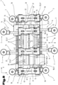
- the Fig. 9 shows the gripping device 1 according to the embodiment according to Fig. 8 in a view from below. For reasons of clarity, parts of the supply means 27 of the vacuum supply system for the holding means 3 are not shown.
- the two adjustment slides 9, 10 are arranged on the underside 17 of the support platform 4. They are connected to the support platform 4 by means of the adjustment slide guides 11, 12 and can be moved in these guides 11, 12 along the first direction 13. They can be fixed in one of a plurality of locking positions as required by means of the locking devices 18 or by means of the locking holes 20 in the underside 17 of the support platform 4.
- the adjustment slides 9, 10 also have cross slides 14 which can be extended in the opposite direction along the second direction 16 and each have a holding means 3.
- the locking device 22 is formed between the adjustment slide 9, 10 and the cross slide 14, whereby the cross slides 14 or their holding means 3 can also be fixed in one of a plurality of predetermined locking positions as required.
- a user can orient themselves using the scales 21, 23, which are attached to the underside of the support platform 4 or to the cross slides 14.
- An area available for adjusting the adjustment slides 9, 10 on the support platform 4 extends along the first direction 13 over a length 38 of the support platform 4.
- the adjustment slide fixing devices or the cross slide fixing devices are not designed as locking devices 18, 22, but that they are Screws 47.
- This variant is also available in the Fig. 9 illustrated, wherein in principle no locking holes 20 are required when fixing by means of screws 47.
- a clamping force can be applied between one of the adjustment slides 9, 10 and the support platform 4, or a clamping force can be applied between the at least one cross slide 14 and one of the adjustment slides 9, 10.
- the gripping device 1 comprises, in addition to the two adjustment slides 9, 10 on the underside 17 of the support platform 4, the further adjustment slide 33 which, by means of its two guide bars 34, 35, can be extended from the front of the support platform 4 in the first direction 13.
- the guide bars 34, 35 of the adjustment slide 33 are aligned parallel to the adjustment slide guides 11, 12 of the adjustment slides 9, 10 on the underside 17 of the support platform 4. This means that the direction of adjustment is the same as that of the adjustment slides 9, 10, namely the first direction 13 (X-direction).
- the gripping device 1 according to this exemplary embodiment has the further adjustment slide 33 on both a first end face 39 and a second end face 40.
- the adjustment slides 33 are each formed with two cross slides 36 that can be extended in opposite directions, wherein the cross slides 36 are each guided with their guide sections 42 in the adjustment slide 33.
- Locking devices 22 are again provided for fixing the cross slides 36 relative to the adjustment slide 33 as required.
- a locking device 18 is also provided between the guide bar 34 of the adjustment slide 33 and the support platform 4.
- a scale 21 is attached to the guide bar 34 for finding the desired position in the X direction.
- the further cross slides 36 also have a scale 23.
- the arrangement of the locking devices 18, 22 as well as the scales 21, 23 in the Fig. 9 shown, offers the advantage for a user that the position adjustments of the holding means 3 can be carried out in a single position, namely looking towards the underside 17 of the carrying platform 4.
- the Fig. 10 shows an embodiment of an adjustment slide 9, 10, 33 with two extendable cross slides 14, 36.
- the guide sections 42 of the cross slides 14, 36 are accommodated in the two cross guides 15.
- the guide sections 42 are profile-shaped and extendable linearly in the transverse guides 15 along the second direction 16.
- the adjustment slide 9, 10, 33 is provided with two cross-slide fixing devices for the releasable fixing of the two cross-slides 14 relative to the adjustment slide 9, 10, as required.
- the cross-slide fixing devices are each provided with two screws 47, whereby a clamping force can be applied between the cross-slides 14, 36 and the adjustment slide 9, 10, 33 by means of the screws 47.
- the cross-slide fixing devices each comprise an eccentric lever 49, which is pivotally connected to the two screws 47.
- Fig. 10 The left cross slide 14, 36 shown is shown in its extended state, while the right cross slide 14, 36 is shown in its fully retracted state. The eccentric lever 49 of the left cross slide 14, 36 is closed, and the cross slide locking device is thus fixed.
- the eccentric lever 49 of the right cross slide 14, 36 is shown open or unfolded. Adjustment or linear displacement of the right cross slide 14, 36 or its guide section 42 is possible in this released or unfixed state.
- cross slide fixing devices shown can also be designed in the same or similar manner as adjustment slide fixing devices for the releasable fixing of the adjustment slides 9, 10 relative to the support platform 4 as required.
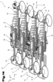
- the Fig. 11 and 12 show two three-dimensional views of a further embodiment of a gripping device 1.
- the perspective corresponds approximately to that of the Fig. 1 and 2 .
- Also in the description of the Fig. 11 and 12 In order to avoid unnecessary repetition, reference is made to the previous sections of the description.
- the gripping device 1 comprises, for example, a total of four adjustment slides 9, 10, 33.
- the two middle adjustment slides 9, 10 can, as shown, each be at least partially accommodated in at least one of the adjustment slide guides 11, 12.
- the two middle adjustment slides 9, 10 are guided, for example, on the two long sides of the support platform 4 in grooves of profiled guide rails.
- the two middle adjustment slides 9, 10 are each mounted in grooves on the underside and top side of the two adjustment slide guides 11, 12 designed as profiled guide rails.
- the two middle adjustment slides 9, 10 are displaceable in the adjustment slide guides 11, 12 relative to the support platform 4 along a first direction 13.
- All adjustment slides 9, 10, 33 each comprise two linearly displaceable or extendable cross slides 14, 36.
- Each of the cross slides 14, 36 has a holding means 3 at its end section.
- the holding means 3 are attached to the respective cross slide 14, 36 by means of an angled sheet metal component. Due to the angular shape, it can be ensured that the holding means 3 contribute as little as possible to the overall thickness or overall height of the gripping device 1 and that no undesirable interfering contours are formed.
- the two outer, further adjustment slides 33 comprise - similar to the Fig. 8 - a first 34 and a second guide bar 35, each of which guide bars 34, 35 are displaceable along the first direction 13, and which guide bars 34, 35 are guided in particular by prism or profile tracks in the support platform 4.
- the two outer adjustment slides 33 can be extended linearly relative to the support platform 4 along the first direction 13 by means of the guide bars 34, 35.
- the adjustment slides 9, 10, 33 are each provided with an adjustment slide fixing device, which can be actuated independently of one another and which are designed to releasably fix the adjustment slides 9, 10, 33 relative to the support platform 4 as needed. Furthermore, the adjustment slides 9, 10, 33 are provided with cross slide fixing devices, which are designed to releasably fix the cross slides 14, 36 relative to the adjustment slides 9, 10, 33 as needed.
- the adjustment slide fixing devices, as well as the cross slide fixing devices are each provided with a clamping lever 48. By means of the clamping levers 48, a clamping force can be applied between the adjustment slides 9, 10, 33 and the support platform 4, in particular between the adjustment slides 9, 10, 33 and the adjustment slide guides 11, 12, as well as between the adjustment slides 9, 10, 33 and the guide bars 34, 35.
- a clamping force can be applied between the cross slides 14, 36 and one of the adjustment slides 9, 10.
- Fig. 11 Almost all clamping levers 48 are shown in their fixed state. Only the clamping lever 48 of the outer cross slide 36, shown in its extended state, is shown open, allowing for movement or adjustment.
- spiral-shaped or coiled and flexible supply lines 50 can be formed.
- the spiral-shaped supply lines 50 for supplying the holding means 3 arranged on the cross slides 14, 36 can be penetrated at least in sections by the respective guide section 42 of the respective cross slide 14, 36.
- an adjusting slide 9, 10, 33 according to the example in the Fig. 12 at least two parallel and relatively displaceable cross slides 14, 36, and that the spiral supply line 50 is at least partially penetrated by the guide section 42 of the respective adjacent or parallel cross slide 14, 36.
- the spiral supply line 50 can expand or pull apart during linear extension or extension.
- FIG. 13 Another adjustment slide 9, 10, 33 with two cross slides 14, 36 is shown in three-dimensional view. To avoid unnecessary repetition, reference is made here to the preceding descriptions, in particular to the description of the Fig. 10 Reference is made.
- the holding means 3 can be fastened.
- the holding means 3 can be adapted as required to the respective workpiece geometry of the workpiece 2 to be manipulated.
- several holding means 3 and, if necessary, also holding means 3 of different sizes can be positioned.
- the cross-slide fixing device can comprise pneumatic fixing devices 52.
- the adjustment slide fixing device can also comprise a pneumatic fixing device 52.
- spiral supply lines 50 are formed and provided for supplying the holding means 3 with negative pressure.
- the spiral supply lines 50 can also serve to supply the pneumatic fixing devices 52.
- the guide section 42 of the cross slides 14, 36 each passes through the spiral supply lines 50.
- the Fig. 14 shows - based on the representation of the Fig. 12 - another embodiment of a gripping device 1 in three-dimensional view.
- energy chains 51 are movably mounted along the first direction 13.
- the energy chains 51 can be arranged on the support platform 4.
- These energy chains 51 are designed to move the adjustment slides 9, 10 and to move the guide beams 34, 35.
- One or more vacuum lines 29 are guided in the energy chains 51. These vacuum lines 29 are in turn fluidly coupled to the spiral supply lines 50 passing through the guide sections 42 of the cross slides 14, 36.
- spiral supply lines 50 can be arranged on the support platform 4 to supply vacuum to the cross slides 14, 36 or the holding means 3. These spiral supply lines 50 are in turn fluidly coupled to the spiral supply lines 50 penetrating the guide sections 42 of the cross slides 14, 36.
Landscapes
- Engineering & Computer Science (AREA)
- Mechanical Engineering (AREA)
- Robotics (AREA)
- Manipulator (AREA)
Claims (20)
- Dispositif de préhension (1) qui est conçu pour prendre et restituer une pièce à usiner (2) à transporter, de préférence en forme de plaque, comprenant :- une plateforme de support (4) avec une face inférieure (17), et une face supérieure (41) opposée à la face inférieure (17),- la plateforme de support (4) étant réalisée sur la face supérieure (41) avec une interface de liaison (5) ou pouvant être couplée avec une interface de liaison (5), laquelle interface de liaison (5) est réalisée pour le couplage du dispositif de préhension (1) avec un manipulateur, et- la plateforme de support (4) étant réalisée sur la face inférieure (17) avec au moins deux guides de chariot de réglage (11, 12),- une pluralité de moyens de maintien (3),- les moyens de maintien (3) étant conçus pour maintenir la pièce à usiner (2),- les moyens de maintien (3) étant couplés à la plateforme de support (4), et- les moyens de maintien (3) présentant des faces de contact (7), lesquelles faces de contact (7) sont opposées à la face inférieure (17) de la plateforme de support (4), et lesquelles faces de contact (7) définissent un plan de contact commun (8),- des moyens d'alimentation (27), lesquels moyens d'alimentation (27) sont conçus pour activer et désactiver les moyens de maintien (3),- au moins deux chariots de réglage (9, 10),- lesquels chariots de réglage (9, 10) sont respectivement reçus ou maintenus, au moins partiellement, dans au moins un des guides du chariot de réglage (11, 12), et- lesquels chariots de réglage (9, 10) peuvent être déplacés dans les guides du chariot de réglage (11, 12) par rapport à la plateforme de support (4) le long d'une première direction (13),- au moins un des chariots de réglage (9, 10) étant formé avec au moins un guide transversal (15), et- au moins un chariot transversal (14)- sur lequel chariot transversal (14) est agencé au moins un des moyens de maintien (3) et- le chariot transversal (14) étant reçu ou maintenu au moins partiellement dans le guide transversal (15), et- le chariot transversal (14) pouvant être déplacé dans le guide transversal (15) par rapport au chariot de réglage (9, 10) le long d'une deuxième direction (16),- la première direction (13) et la deuxième direction (16) étant orthogonales l'une par rapport à l'autre, caractérisé
en ce qu'une section de guidage (42) de l'au moins un chariot transversal (14), reçue ou maintenue dans l'au moins un guide transversal (15), est profilée, cette section de guidage (42) pouvant être extraite linéairement dans le guide transversal (15). - Dispositif de préhension (1) selon la revendication 1, caractérisé en ce qu'au moins l'un des chariots de réglage (9, 10) est réalisé avec deux guides transversaux (15) parallèles l'un à l'autre, et en ce qu'un chariot transversal (14) extractible est reçu dans chaque guide transversal (15), au moins l'un des moyens de maintien (3) étant disposé sur chaque chariot transversal (14), et les moyens de maintien (3) étant réalisés sur des sections d'extrémité opposées l'une à l'autre des deux chariots transversaux (14).
- Dispositif de préhension (1) selon l'une des revendications précédentes, caractérisé en ce que les chariots de réglage (9, 10) sont réalisés chacun avec un dispositif de fixation du chariot de réglage, lesquels dispositifs de fixation du chariot de réglage peuvent être actionnés indépendamment l'un de l'autre, et lesquels dispositifs de fixation du chariot de réglage sont destinés à la fixation détachable en cas de besoin des chariots de réglage (9, 10) par rapport à la plateforme de support (4) et/ou en ce que les chariots de réglage (9, 10) sont réalisés avec un dispositif de fixation du chariot transversal, lequel dispositif de fixation du chariot transversal est réalisé pour la fixation détachable en cas de besoin d'au moins un chariot transversal (14) par rapport au chariot de réglage (9, 10).
- Dispositif de préhension (1) selon l'une des revendications précédentes, caractérisé en ce qu'au moins une première échelle (21) est formée sur la plateforme de support (4) le long de la première direction (13) et/ou en ce qu'une deuxième échelle (23) est formée sur au moins un chariot transversal (14) le long de la deuxième direction (16), la première échelle (21) et la deuxième échelle (23) étant de préférence agencées parallèlement au plan de contact (8), de sorte que celles-ci sont visibles lorsque l'on observe la face inférieure (17) de la plateforme de support (4).
- Dispositif de préhension (1) selon la revendication 3 ou 4, caractérisé en ce que le dispositif de fixation du chariot de réglage est réalisé sous la forme d'un dispositif d'encliquetage du chariot de réglage (18), et/ou en ce que le dispositif de fixation du chariot transversal est réalisé sous la forme d'un dispositif d'encliquetage du chariot transversal (22), et en ce que la plateforme de support (4) est réalisée avec une pluralité d'évidements d'encliquetage disposés à équidistance les uns des autres le long de la première direction (13), et en ce qu'un élément d'encliquetage du dispositif d'encliquetage du chariot de réglage (18) peut être mis en prise avec les évidements d'encliquetage de la plateforme de support (4), et en ce que le chariot transversal (14) est formé avec une pluralité d'évidements d'encliquetage placés à équidistance les uns des autres le long de la deuxième direction (16) et en ce qu'un élément d'encliquetage du dispositif d'encliquetage du chariot transversal (22) peut être mis en prise avec les évidements d'encliquetage du chariot transversal (14).
- Dispositif de préhension (1) selon la revendication 5, caractérisé en ce que l'élément d'encliquetage du dispositif d'encliquetage du chariot de réglage (18) et/ou l'élément d'encliquetage du dispositif d'encliquetage du chariot transversal (22) est réalisé sous forme de boulon (19), lequel boulon (19) peut être mis en prise avec les évidements d'encliquetage de la plateforme de support (4) et/ou avec les évidements d'encliquetage du chariot transversal (14).
- Dispositif de préhension (1) selon l'une des revendications 3 à 6, caractérisé en ce que le dispositif de fixation du chariot de réglage comprend au moins une vis (47), une force de serrage pouvant être appliquée au moyen de la vis (47) entre l'un des chariots de réglage (9, 10) et la plateforme de support (4), et/ou en ce que le dispositif de fixation du chariot transversal comprend au moins une vis (47), une force de serrage pouvant être appliquée au moyen de la vis (47) entre ledit au moins un chariot transversal (14) et l'un des chariots de réglage (9, 10).
- Dispositif de préhension (1) selon l'une des revendications 3 à 7, caractérisé en ce que le dispositif de fixation du chariot de réglage comprend au moins un levier de serrage (48), un levier excentrique (49) ou un levier de tension, une force de serrage pouvant être appliquée entre l'un des chariots de réglage (9, 10) au moyen du levier de serrage (48), du levier excentrique (49) ou du levier de tension, et la plate-forme de support (4), et/ou en ce que le dispositif de fixation du chariot transversal comprend au moins un levier de serrage (48), un levier excentrique (49) ou un levier de tension, une force de serrage pouvant être appliquée entre l'au moins un chariot transversal (14) et l'un des chariots de réglage (9, 10) au moyen du levier de serrage (48), du levier excentrique (49) ou du levier de tension.
- Dispositif de préhension (1) selon l'une des revendications 3 à 8, caractérisé en ce que le dispositif de fixation du chariot de réglage et/ou le dispositif de fixation du chariot transversal comprend un dispositif de fixation pneumatique (52).
- Dispositif de préhension (1) selon l'une des revendications précédentes, caractérisé en ce que les guides de chariot de réglage (11, 12) sont réalisés sous forme de pistes prismatiques pour l'engagement par complémentarité de forme avec des sections des chariots de réglage (9, 10), en particulier en ce que les guides de chariot de réglage (11, 12) sont réalisés sous forme de pistes prismatiques pour l'engagement par complémentarité de forme avec des sections des deux chariots de réglage (9, 10).
- Dispositif de préhension (1) selon l'une des revendications précédentes, caractérisé en ce que la section de guidage (42) de l'au moins un chariot transversal (14) est réalisé au moins par sections avec un profilé creux (45), lequel profilé creux (45) est réalisé sous la forme d'un canal de dépression (30), le canal de dépression (30) étant relié par fluide aux moyens d'alimentation (27) et avec l'au moins un moyen de maintien (3) agencé sur le chariot transversal (14).
- Dispositif de préhension (1) selon l'une des revendications précédentes, caractérisé en ce qu'au moins une ligne d'alimentation (50) en forme de spirale est formée, laquelle au moins une ligne d'alimentation (50) en forme de spirale est prévue pour alimenter au moins l'un des moyens de maintien (3) avec une pression négative.
- Dispositif de préhension (1) selon la revendication 12, caractérisé en ce que l'au moins une ligne d'alimentation (50) en forme de spirale est traversée au moins par sections par la section de guidage (42) de l'au moins un chariot transversal (14).
- Dispositif de préhension (1) selon l'une des revendications précédentes, caractérisé en ce que les moyens d'alimentation (27) comprennent un îlot de vannes (28), lequel îlot de vannes (28) est relié par fluide aux moyens de maintien (3) via des vannes d'arrêt.
- Dispositif de préhension (1) selon l'une des revendications précédentes, caractérisé en ce qu'un autre chariot de réglage (33) est formé, lequel chariot de réglage (33) comprend une première barre de guidage (34) et une deuxième barre de guidage (35), lesquelles barres de guidage (34, 35) peuvent être déplacées le long de la première direction (13), et lesquelles barres de guidage (34, 35) sont guidées, en particulier à travers des ouvertures, sur une face frontale (39, 40) de la plateforme de support (4) ou à travers des pistes prismatiques ou profilées dans la plateforme de support (4), le chariot de réglage (33) pouvant être extrait de manière linéaire par rapport à la plateforme de support (4) le long de la première direction (13) au moyen des barres de guidage (34, 35).
- Dispositif de préhension (1) selon la revendication 15, caractérisé en ce qu'au moins un autre chariot transversal (36) est formé, chariot transversal (36) sur lequel est agencé au moins l'un des moyens de maintien (3), et lequel chariot transversal (36) est reçu au moins partiellement dans un guide transversal (15) de l'autre chariot de réglage (33), et lequel chariot transversal (36) peut être déplacé dans le guide transversal (15) par rapport au chariot de réglage (33) le long de la deuxième direction (16), une section de guidage (42) de l'autre chariot de réglage (33) reçue dans l'au moins un guide transversal (15) étant profilée, en particulier en forme de profil creux, et cette section de guidage (42) pouvant être extraite de manière linéaire dans le guide transversal (15).
- Dispositif de préhension (1) selon la revendication 16, caractérisé en ce qu'un tube à dépression (37) extensible linéairement par rapport à la plateforme de support (4) est formé parallèlement aux barres de guidage (34, 35), lequel tube à dépression (37) est relié par fluide aux moyens d'alimentation (27) et à au moins un moyen de maintien (3) agencé sur l'autre chariot transversal (36) agencé sur le chariot de réglage (33).
- Dispositif de préhension (1) selon l'une des revendications 15 à 17, caractérisé en ce que l'au moins une ligne d'alimentation (50) en forme de spirale est traversée au moins partiellement par au moins une des barres de guidage (34, 35) des chariots de réglage (9, 10) ou en ce que l'au moins une ligne d'alimentation (50) en forme de spirale est agencée entre les deux barres de guidage (34, 35).
- Dispositif de préhension (1) selon l'une des revendications précédentes, caractérisé en ce qu'au moins une chaîne énergétique (51) montée mobile le long de la première direction (13) est réalisée, laquelle chaîne énergétique (51) est réalisée pour le déplacement des chariots de réglage (9, 10) et/ou pour le déplacement des barres de guidage (34, 35), et en ce qu'au moins une ligne d'alimentation inférieure (29) est guidée dans la chaîne énergétique (51).
- Manipulateur conçu pour prendre et restituer une pièce à usiner (2) à transporter, de préférence en forme de plaque, comprenant un dispositif de préhension (1), caractérisé en ce que le dispositif de préhension (1) est conçu selon l'une des revendications 1 à 19.
Applications Claiming Priority (2)
| Application Number | Priority Date | Filing Date | Title |
|---|---|---|---|
| ATA50215/2021A AT524881B1 (de) | 2021-03-26 | 2021-03-26 | Greifvorrichtung mit verstellbaren Schlitten |
| PCT/AT2022/060093 WO2022198256A1 (fr) | 2021-03-26 | 2022-03-25 | Dispositif de préhension à coulisseau réglable |
Publications (3)
| Publication Number | Publication Date |
|---|---|
| EP4313520A1 EP4313520A1 (fr) | 2024-02-07 |
| EP4313520C0 EP4313520C0 (fr) | 2025-04-30 |
| EP4313520B1 true EP4313520B1 (fr) | 2025-04-30 |
Family
ID=81327547
Family Applications (1)
| Application Number | Title | Priority Date | Filing Date |
|---|---|---|---|
| EP22715516.5A Active EP4313520B1 (fr) | 2021-03-26 | 2022-03-25 | Dispositif de préhension à coulisseau réglable |
Country Status (6)
| Country | Link |
|---|---|
| US (1) | US20240149469A1 (fr) |
| EP (1) | EP4313520B1 (fr) |
| JP (1) | JP7612043B2 (fr) |
| CN (1) | CN117062696A (fr) |
| AT (1) | AT524881B1 (fr) |
| WO (1) | WO2022198256A1 (fr) |
Families Citing this family (5)
| Publication number | Priority date | Publication date | Assignee | Title |
|---|---|---|---|---|
| CA3179043A1 (fr) * | 2021-10-14 | 2023-04-14 | Gmr Quality Stone Products | Systeme de manipulation de dalle |
| DE102023129990A1 (de) * | 2023-10-30 | 2025-04-30 | TRUMPF Werkzeugmaschinen SE + Co. KG | Maschinelle Anordnung und Verfahren zur Handhabung von zumindest einem plattenförmigen Werkstück |
| DE102023133603A1 (de) * | 2023-11-30 | 2025-06-05 | J.Schmalz Gmbh | Unterdruckhandhabungsvorrichtung und Unterdruckhandhabungssystem zum Greifen eines Objekts |
| CN118746087B (zh) * | 2024-07-08 | 2025-01-24 | 深圳市小间距光电有限公司 | 一种基于异形led显示屏的调节装置 |
| CN119755475A (zh) * | 2025-03-04 | 2025-04-04 | 天津赛象科技股份有限公司 | 一种适用于激光标线器的调节装置 |
Citations (2)
| Publication number | Priority date | Publication date | Assignee | Title |
|---|---|---|---|---|
| EP2401118B1 (fr) * | 2009-02-28 | 2013-06-12 | Abb Ag | Dispositif d'outillage destiné à un manipulateur |
| EP3031586A1 (fr) * | 2014-12-11 | 2016-06-15 | Fagor, S. Coop. | Dispositif de préhension flexible pour un système d'empilage de pièces et procédé de positionnement pour le positionnement d'éléments de préhension pour un système d'empilage de pièces |
Family Cites Families (21)
| Publication number | Priority date | Publication date | Assignee | Title |
|---|---|---|---|---|
| US4228993A (en) * | 1978-05-01 | 1980-10-21 | Ppg Industries, Inc. | Sheet orienting and transporting frame |
| JPS59157806U (ja) * | 1983-04-08 | 1984-10-23 | 矢崎化工株式会社 | 成形品の取出機 |
| JPH0637908Y2 (ja) * | 1989-04-21 | 1994-10-05 | 株式会社安川電機 | ロボットハンド |
| JPH03122069U (fr) * | 1990-03-26 | 1991-12-12 | ||
| ES2082033T3 (es) * | 1991-05-02 | 1996-03-16 | Ligmatech Maschb Gmbh | Dispositivo para manipular piezas en forma de planchas. |
| DE29905687U1 (de) | 1999-03-27 | 1999-07-08 | DE-STA-CO Metallerzeugnisse GmbH, 61449 Steinbach | Trageinrichtung |
| US6796588B2 (en) | 2002-08-27 | 2004-09-28 | Tsung-Chang Hsieh | Suction device with telescopic evacuating pipes |
| WO2006089327A1 (fr) | 2005-02-28 | 2006-08-31 | Trumpf Maschinen Austria Gmbh & Co. Kg. | Dispositif de prehension |
| KR100965098B1 (ko) * | 2009-11-12 | 2010-06-22 | (주)우신시스템 | 다차종 패널 세팅용 로봇 행거 |
| ITTO20120162U1 (it) * | 2012-09-26 | 2014-03-27 | Tecno Ct S R L Con Socio U Nico | Dispositivo di movimentazione lineare di tipo telescopico |
| DE102013105383B3 (de) * | 2013-05-24 | 2014-07-24 | Schindler Handhabetechnik Gmbh | Vorrichtung zum pneumatischen Halten und Heben von Glasplatten |
| EP3188993A4 (fr) * | 2014-10-28 | 2018-08-29 | Festo AG & Co. KG | Extrémité universelle d'outil formant bras robotique |
| US9757830B2 (en) * | 2014-12-04 | 2017-09-12 | Ronald P. Allen | Fencing assembly apparatus |
| CN105742224A (zh) * | 2014-12-11 | 2016-07-06 | 南京瀚宇彩欣科技有限责任公司 | 衬底吸附装置 |
| JP6672771B2 (ja) * | 2015-12-18 | 2020-03-25 | 村田機械株式会社 | 吸着装置、及びワーク支持装置 |
| CN106826893A (zh) * | 2016-12-16 | 2017-06-13 | 北京京东尚科信息技术有限公司 | 端拾器和机器人搬运系统 |
| EP3758900B1 (fr) * | 2018-03-01 | 2024-09-25 | Güdel AG | Installation pour le traitement de pièces plates |
| CN208867201U (zh) * | 2018-10-17 | 2019-05-17 | 刘强 | 一种工业机器人抓手 |
| IT201900002917A1 (it) * | 2019-02-28 | 2020-08-28 | Raimondi Spa | Dispositivo di presa di elementi lastriformi |
| CN210335998U (zh) * | 2019-05-16 | 2020-04-17 | 一汽-大众汽车有限公司 | 通用型吸盘机械手 |
| CN110977582B (zh) * | 2019-12-10 | 2021-08-20 | 安庆师范大学 | 一种数控机床机械手 |
-
2021
- 2021-03-26 AT ATA50215/2021A patent/AT524881B1/de active
-
2022
- 2022-03-25 CN CN202280023844.0A patent/CN117062696A/zh active Pending
- 2022-03-25 JP JP2023559085A patent/JP7612043B2/ja active Active
- 2022-03-25 US US18/281,402 patent/US20240149469A1/en active Pending
- 2022-03-25 EP EP22715516.5A patent/EP4313520B1/fr active Active
- 2022-03-25 WO PCT/AT2022/060093 patent/WO2022198256A1/fr not_active Ceased
Patent Citations (2)
| Publication number | Priority date | Publication date | Assignee | Title |
|---|---|---|---|---|
| EP2401118B1 (fr) * | 2009-02-28 | 2013-06-12 | Abb Ag | Dispositif d'outillage destiné à un manipulateur |
| EP3031586A1 (fr) * | 2014-12-11 | 2016-06-15 | Fagor, S. Coop. | Dispositif de préhension flexible pour un système d'empilage de pièces et procédé de positionnement pour le positionnement d'éléments de préhension pour un système d'empilage de pièces |
Also Published As
| Publication number | Publication date |
|---|---|
| AT524881A1 (de) | 2022-10-15 |
| JP2024515474A (ja) | 2024-04-10 |
| CN117062696A (zh) | 2023-11-14 |
| EP4313520C0 (fr) | 2025-04-30 |
| WO2022198256A1 (fr) | 2022-09-29 |
| US20240149469A1 (en) | 2024-05-09 |
| AT524881B1 (de) | 2024-09-15 |
| EP4313520A1 (fr) | 2024-02-07 |
| JP7612043B2 (ja) | 2025-01-10 |
Similar Documents
| Publication | Publication Date | Title |
|---|---|---|
| EP4313520B1 (fr) | Dispositif de préhension à coulisseau réglable | |
| EP0343552B1 (fr) | Presse à découper avec un outil de découpage échangeable et avancement de pièce à travailler | |
| EP3197639B1 (fr) | Dispositif d'usinage | |
| EP3370892B1 (fr) | Système de préhension pour presse à plier | |
| EP3180138B1 (fr) | Outil de cintrage et dispositif de préhension servant à manipuler l'outil de cintrage | |
| EP2694231B1 (fr) | Dispositif de transfert pour une presse ou un train de presses comprenant une transmission et support de base échangeable | |
| DE9315209U1 (de) | Abkantpresse | |
| EP3740330A1 (fr) | Cintreuse et procédé de cintrage d'une pièce composée d'un matériau plat | |
| DE202008006667U1 (de) | Drehmaschine und Vertikalschlitten-Baugruppe für eine Drehmaschine | |
| EP3302840B1 (fr) | Installation de fabrication pour la fabrication de pièces en tôle et procédé à cet effet | |
| EP2907618A1 (fr) | Recouvrement de machine | |
| EP2944390B1 (fr) | Outil de pliage et procédé de changement d'un tel outil | |
| EP3416764B1 (fr) | Dispositif de changement d'outil pour presse plieuse et procédé permettant de réaliser un changement d'outil | |
| EP0195184B1 (fr) | Dispositif d'interchange de mors | |
| WO2004108349A2 (fr) | Machine-outil | |
| DE69820564T2 (de) | Maschine zum Schneiden von flächigen Körpern mit einem zweiten rotierbaren Tisch | |
| DE3101765A1 (de) | Werkzeugmaschine mit werkstueckzufuehrorganen | |
| AT518111B1 (de) | Biegepresse mit Werkzeugwechselvorrichtung | |
| DE19636463A1 (de) | Blechbearbeitungsmaschine für plattenförmige Werkstücke mit einem in einzelne Segmente unterteilten Niederhalter | |
| DE102017110931A1 (de) | Bearbeitungszentrum | |
| DE102010025521B4 (de) | Maschine zum Bearbeiten von Tafeln aus Holz oder dergleichen | |
| EP1272405A2 (fr) | Dispositif pour transporter des pieces plates de maniere suspendue | |
| DE8412359U1 (de) | Werkzeugmaschine | |
| DE19703240A1 (de) | Vorrichtung zum Handhaben und Bearbeiten von vorzugsweise plattenförmigen Werkstücken | |
| DE102010033311A1 (de) | Greifvorrichtung für CNC-Maschine |
Legal Events
| Date | Code | Title | Description |
|---|---|---|---|
| STAA | Information on the status of an ep patent application or granted ep patent |
Free format text: STATUS: UNKNOWN |
|
| STAA | Information on the status of an ep patent application or granted ep patent |
Free format text: STATUS: THE INTERNATIONAL PUBLICATION HAS BEEN MADE |
|
| PUAI | Public reference made under article 153(3) epc to a published international application that has entered the european phase |
Free format text: ORIGINAL CODE: 0009012 |
|
| STAA | Information on the status of an ep patent application or granted ep patent |
Free format text: STATUS: REQUEST FOR EXAMINATION WAS MADE |
|
| 17P | Request for examination filed |
Effective date: 20231024 |
|
| AK | Designated contracting states |
Kind code of ref document: A1 Designated state(s): AL AT BE BG CH CY CZ DE DK EE ES FI FR GB GR HR HU IE IS IT LI LT LU LV MC MK MT NL NO PL PT RO RS SE SI SK SM TR |
|
| DAV | Request for validation of the european patent (deleted) | ||
| DAX | Request for extension of the european patent (deleted) | ||
| GRAP | Despatch of communication of intention to grant a patent |
Free format text: ORIGINAL CODE: EPIDOSNIGR1 |
|
| STAA | Information on the status of an ep patent application or granted ep patent |
Free format text: STATUS: GRANT OF PATENT IS INTENDED |
|
| INTG | Intention to grant announced |
Effective date: 20241107 |
|
| GRAS | Grant fee paid |
Free format text: ORIGINAL CODE: EPIDOSNIGR3 |
|
| GRAA | (expected) grant |
Free format text: ORIGINAL CODE: 0009210 |
|
| STAA | Information on the status of an ep patent application or granted ep patent |
Free format text: STATUS: THE PATENT HAS BEEN GRANTED |
|
| AK | Designated contracting states |
Kind code of ref document: B1 Designated state(s): AL AT BE BG CH CY CZ DE DK EE ES FI FR GB GR HR HU IE IS IT LI LT LU LV MC MK MT NL NO PL PT RO RS SE SI SK SM TR |
|
| REG | Reference to a national code |
Ref country code: CH Ref legal event code: EP Ref country code: GB Ref legal event code: FG4D Free format text: NOT ENGLISH |
|
| REG | Reference to a national code |
Ref country code: IE Ref legal event code: FG4D Free format text: LANGUAGE OF EP DOCUMENT: GERMAN |
|
| REG | Reference to a national code |
Ref country code: DE Ref legal event code: R096 Ref document number: 502022003775 Country of ref document: DE |
|
| U01 | Request for unitary effect filed |
Effective date: 20250522 |
|
| U07 | Unitary effect registered |
Designated state(s): AT BE BG DE DK EE FI FR IT LT LU LV MT NL PT RO SE SI Effective date: 20250602 |
|
| PG25 | Lapsed in a contracting state [announced via postgrant information from national office to epo] |
Ref country code: ES Free format text: LAPSE BECAUSE OF FAILURE TO SUBMIT A TRANSLATION OF THE DESCRIPTION OR TO PAY THE FEE WITHIN THE PRESCRIBED TIME-LIMIT Effective date: 20250430 |
|
| PG25 | Lapsed in a contracting state [announced via postgrant information from national office to epo] |
Ref country code: GR Free format text: LAPSE BECAUSE OF FAILURE TO SUBMIT A TRANSLATION OF THE DESCRIPTION OR TO PAY THE FEE WITHIN THE PRESCRIBED TIME-LIMIT Effective date: 20250731 Ref country code: NO Free format text: LAPSE BECAUSE OF FAILURE TO SUBMIT A TRANSLATION OF THE DESCRIPTION OR TO PAY THE FEE WITHIN THE PRESCRIBED TIME-LIMIT Effective date: 20250730 |
|
| PG25 | Lapsed in a contracting state [announced via postgrant information from national office to epo] |
Ref country code: PL Free format text: LAPSE BECAUSE OF FAILURE TO SUBMIT A TRANSLATION OF THE DESCRIPTION OR TO PAY THE FEE WITHIN THE PRESCRIBED TIME-LIMIT Effective date: 20250430 |
|
| PG25 | Lapsed in a contracting state [announced via postgrant information from national office to epo] |
Ref country code: HR Free format text: LAPSE BECAUSE OF FAILURE TO SUBMIT A TRANSLATION OF THE DESCRIPTION OR TO PAY THE FEE WITHIN THE PRESCRIBED TIME-LIMIT Effective date: 20250430 |
|
| PG25 | Lapsed in a contracting state [announced via postgrant information from national office to epo] |
Ref country code: RS Free format text: LAPSE BECAUSE OF FAILURE TO SUBMIT A TRANSLATION OF THE DESCRIPTION OR TO PAY THE FEE WITHIN THE PRESCRIBED TIME-LIMIT Effective date: 20250731 |
|
| PG25 | Lapsed in a contracting state [announced via postgrant information from national office to epo] |
Ref country code: IS Free format text: LAPSE BECAUSE OF FAILURE TO SUBMIT A TRANSLATION OF THE DESCRIPTION OR TO PAY THE FEE WITHIN THE PRESCRIBED TIME-LIMIT Effective date: 20250830 |
|
| PG25 | Lapsed in a contracting state [announced via postgrant information from national office to epo] |
Ref country code: SM Free format text: LAPSE BECAUSE OF FAILURE TO SUBMIT A TRANSLATION OF THE DESCRIPTION OR TO PAY THE FEE WITHIN THE PRESCRIBED TIME-LIMIT Effective date: 20250430 |
|
| PG25 | Lapsed in a contracting state [announced via postgrant information from national office to epo] |
Ref country code: CZ Free format text: LAPSE BECAUSE OF FAILURE TO SUBMIT A TRANSLATION OF THE DESCRIPTION OR TO PAY THE FEE WITHIN THE PRESCRIBED TIME-LIMIT Effective date: 20250430 |
|
| PG25 | Lapsed in a contracting state [announced via postgrant information from national office to epo] |
Ref country code: SK Free format text: LAPSE BECAUSE OF FAILURE TO SUBMIT A TRANSLATION OF THE DESCRIPTION OR TO PAY THE FEE WITHIN THE PRESCRIBED TIME-LIMIT Effective date: 20250430 |
|
| PLBE | No opposition filed within time limit |
Free format text: ORIGINAL CODE: 0009261 |
|
| STAA | Information on the status of an ep patent application or granted ep patent |
Free format text: STATUS: NO OPPOSITION FILED WITHIN TIME LIMIT |
|
| REG | Reference to a national code |
Ref country code: CH Ref legal event code: L10 Free format text: ST27 STATUS EVENT CODE: U-0-0-L10-L00 (AS PROVIDED BY THE NATIONAL OFFICE) Effective date: 20260311 |
|
| 26N | No opposition filed |
Effective date: 20260202 |