EP4313833B1 - Agencement de cabine pour un ascenseur à double étage et ascenseur à double étage - Google Patents
Agencement de cabine pour un ascenseur à double étage et ascenseur à double étage Download PDFInfo
- Publication number
- EP4313833B1 EP4313833B1 EP22711242.2A EP22711242A EP4313833B1 EP 4313833 B1 EP4313833 B1 EP 4313833B1 EP 22711242 A EP22711242 A EP 22711242A EP 4313833 B1 EP4313833 B1 EP 4313833B1
- Authority
- EP
- European Patent Office
- Prior art keywords
- cabin
- elevator car
- push chain
- car
- coupled
- Prior art date
- Legal status (The legal status is an assumption and is not a legal conclusion. Google has not performed a legal analysis and makes no representation as to the accuracy of the status listed.)
- Active
Links
Images


Classifications
-
- B—PERFORMING OPERATIONS; TRANSPORTING
- B66—HOISTING; LIFTING; HAULING
- B66B—ELEVATORS; ESCALATORS OR MOVING WALKWAYS
- B66B11/00—Main component parts of lifts in, or associated with, buildings or other structures
- B66B11/02—Cages, i.e. cars
- B66B11/0206—Car frames
- B66B11/0213—Car frames for multi-deck cars
- B66B11/022—Car frames for multi-deck cars with changeable inter-deck distances
Definitions
- the present invention relates to a car arrangement for a double-decker elevator and a double-decker elevator with such a car arrangement.
- a double-decker elevator is characterized by a car arrangement with a car frame and two cabins arranged one above the other. These two cabins allow two different floors to be reached simultaneously.
- the floors are of different heights, resulting in different vertical distances between the elevator entrances.
- this vertical distance at least one of the two cars can be moved vertically relative to the other car and, as a rule, relative to the car frame. This vertical displacement is achieved using a displacement device.
- the displacement device can, for example, have one or more screw spindle drives and/or scissor-like connecting links, via which the two cars are connected to each other.
- a spindle drive has at least one spindle and a rack, into which the spindle engages.
- the spindle can be arranged on the car frame of the car arrangement or on the car to be moved.
- the rack can accordingly be arranged on the car to be moved or on the car frame.
- a hydraulic displacement device can be provided for moving the cabin. The distance between the cabins can be adjusted during travel using a control system to match the floor spacing between the two floors to be reached and the corresponding distance between the entrances.
- EP 3 514 096 A1 Describes a double-deck elevator with two cars, where the vertical distance between the cars can be adjusted using a pull chain and several deflection elements. The corresponding drive device increases the height of the corresponding car arrangement.
- EP 3 514 096 A1 discloses a car arrangement according to the preamble of claim 1.
- US 2020 / 0 239 289 A1 describes a push chain in which chain links of the push chain engage with each other in such a form-fitting manner under pressure load that a force-absorbing section of the push chain is stable under the pressure load in a direction in which the chain links can be pivoted against each other in the absence of pressure load.
- WO 2015/043766 A1 Describes an elevator with two cars, each of which can be moved independently of each other in an elevator shaft by means of a drive.
- the cars can be temporarily coupled together using a mechanical coupling element, for example, in the form of a support chain.
- the distance between the coupled cars is adjusted using the drives assigned to the cars.
- the size of the elevator shaft plays a key role.
- the relocation device should have as little space as possible, especially horizontally.
- both of the aforementioned relocation devices require a relatively large amount of space, both horizontally and vertically, with the space available in an elevator shaft, particularly horizontally, generally being very limited.
- the hydraulic relocation device can cause odors due to the oil used in it. can tend to, whereby the smell may be unpleasant in the corresponding cabin.
- One of the challenges in the design of such double-decker elevators is to design components for moving and driving the cabin to be moved in a way that is as space-saving as possible and, in addition, lightweight and cost-effective.
- a car assembly for a double-deck elevator that allows the distance between an upper car and a lower car to be adjusted using a particularly compact and lightweight displacement and drive device. Furthermore, there may be a need for a corresponding double-deck elevator.
- a first aspect of the invention relates to a car assembly for a double-deck elevator.
- the car assembly comprises a car frame, a first car, a second car, a push chain, and a drive device.
- the first car is coupled to the car frame.
- the second car is arranged on the car frame above or below the first car.
- the second car is coupled to the car frame such that it is movable vertically relative to the car frame and relative to the first car.
- the push chain is coupled to the first car or the car frame by a first end of a force-absorbing section of the push chain. Furthermore, the push chain is coupled to the second car by an opposite second end of the force-absorbing section.
- the push chain is arranged such that the second car exerts a compressive load on the force-absorbing section of the push chain due to gravity.
- the drive device is coupled to the push chain and is designed to displace the second car vertically relative to the first car by means of the push chain.
- the second car which is arranged in the car frame above or below the first car and is movable in the vertical direction, can be displaced vertically relative to the first car, so that the vertical distance between the cars is adjustable, in particular depending on the corresponding access points to the cars on different floors of a building.
- the vertical distance is adjusted in particular by changing the length of the force-absorbing section, wherein this length is achieved by moving the push chain by means of the drive device.
- car frame can generally be understood as a frame that can be moved between several levels or floors, for example in an elevator shaft, and has at least one cabin, or in the present case of a double-decker elevator with at least two cabins, for transporting people or loads.
- the car frame can in particular be a frame-like construction for supporting the cabins and is also called a safety frame.
- the car frame can, for example, be guided along at least one guide rail running in an elevator shaft. Such guide rails can be arranged on one side or on two opposite sides of the elevator shaft.
- a safety gear can be integrated into the car frame and serves to slow the car frame down in the event of excessive speed.
- the car frame can comprise the two double-decker cars for simultaneously accessing the two different floors.
- a displacement device can be arranged, by means of which at least one of the two cars can be displaced in the vertical direction relative to the other car and, as a rule, relative to the car frame.
- the aforementioned drive device and the push chain form such a Displacement device.
- the approach presented here proposes displacing the second car using a push chain. The vertical distance between the cars is determined by the length of the force-absorbing section of the push chain.
- This length can be adjusted using the drive unit, thereby displacing the second car relative to the first car.
- a guide structure is also installed within the car frame, in which the two cars are arranged one above the other, to guide the car to be displaced during its movement.
- the weight of the second cabin acts on the push chain.
- the second cabin can stand on the push chain.
- the section of the push chain on which the weight acts and which accordingly supports the weight of the second cabin is the force-absorbing section.
- the push chain In order for the length of the force-absorbing section to be variable, the push chain must be longer than the force-absorbing section.
- the section of the push chain on which the weight of the second cabin does not act can be referred to as the remaining section of the push chain.
- the length of the remaining section changes depending on the length of the force-absorbing section. In particular, the length of the remaining section increases as the length of the force-absorbing section decreases, and vice versa.
- the push chain exhibits shock properties when the second cabin is lifted. Therefore, the push chain cannot break.
- the push chain and the drive device that drives it require relatively little space, especially in the horizontal direction, compared to the spindle drive and the hydraulic displacement device.
- the drive device can generally be understood to mean a motor by which the push chain is moved in such a way that the length of the force-absorbing section of the chain changes, so that the corresponding car, for example the second car, can be raised and/or lowered relative to the car frame and the first car.
- the push chain can be designed in such a way that chain links of the push chain engage with each other in a form-fitting manner under a pressure load, such that the force-absorbing section of the push chain under the pressure load in a direction in which chain links of the push chain can pivot against each other in the absence of pressure load, is stable.
- the push chain can always be stable in a first lateral direction, which is perpendicular to a longitudinal direction of the push chain when the push chain is unwound, and can be unstable, in particular pivotable, in particular bendable, at the transition of the chain links in a second lateral direction, which is perpendicular to the longitudinal direction of the push chain and perpendicular to the first lateral direction when the push chain is unloaded and/or unwound.
- the chain links of the push chain can engage with one another in a form-fitting manner under compressive load such that the push chain is stable in the second lateral direction. The push chain can thus withstand high compressive loads.
- the drive device can be designed and coupled to the push chain in such a way that when the second cabin is displaced in the direction of gravity, the push chain drives the drive device in a generator-like manner.
- the potential energy stored in the raised second cabin can be converted into electrical energy by means of the push chain and the drive mechanism in generator mode.
- the weight of the second cabin acts on the push chain, which drives the drive mechanism, which in turn acts as a generator and generates electrical energy.
- the electrical energy can be stored and reused, for example, to power the drive mechanism the next time the second cabin is moved.
- the drive device can comprise the motor and an output arranged on a shaft of the motor and engaging with the push chain.
- the output can be formed, for example, by a gear whose teeth engage with the chain links of the push chain.
- the drive device can further comprise a housing and/or a guide for the remaining section and optionally a part of the force-absorbing section of the push chain.
- the motor and/or the remaining section can optionally be arranged in or on the housing.
- the drive device can be arranged on the first car or on the second car.
- the drive device can be arranged on the car frame or on the second car.
- the drive device can engage the push chain at the first end of the force-absorbing section or at the second end of the force-absorbing section.
- the push chain can be arranged such that the remaining section of the push chain, which is not the force-absorbing section, is located between the cabins. This is particularly advantageous when the push chain is coupled to the first cabin. For example, if the push chain is coupled to the first cabin, the remaining section can be guided along the cabin on which the drive device is arranged.
- the push chain can be arranged such that the remaining section of the push chain extends at least partially in the horizontal direction. This can contribute to the particularly small vertical space requirement of the relocation device.
- the first car can have a first force-absorbing region
- the car frame can have the first force-absorbing region.
- the second car can have a second force-absorbing region.
- the push chain can be coupled to the first force-absorbing region by the first end of the force-absorbing section and to the second force-absorbing region by the second end of the force-absorbing section.
- the force-absorbing section can extend from the first force-absorbing region to the second force-absorbing region. A vertical distance between the two cars depends on a length of the force-absorbing section.
- the drive device can be designed to move the push chain in order to displace the second car in the vertical direction such that the length of the force-absorbing section changes.
- the second force-absorbing region is the region where the weight of the second car is transferred to the force-absorbing section of the push chain.
- the first force-absorbing region is the region where the corresponding compressive load is transferred from the force-absorbing section to the first car or the car frame.
- the drive device can be arranged at the first end or at the second end of the force-absorbing section. At the end of the force-absorbing section at which the drive device is arranged, the drive device, for example its output, can form the corresponding force-absorbing region.
- a rotatable deflection device for example a gear wheel that engages with the push chain, can be arranged at the first end or at the second end of the force-absorbing section. In this case, the deflection device can form the corresponding force-absorbing region.
- the first car can be coupled to the car frame such that it is arranged to be movable in the vertical direction relative to the car frame.
- the car assembly can have a further push chain coupled to the first car and the car frame.
- the car assembly can have a further drive device coupled to the further push chain.
- the further drive device can be configured to displace the first car in the vertical direction relative to the car frame by means of the further push chain.
- both cars can be displaced vertically relative to the car frame, wherein the additional push chain can be arranged to displace the first car.
- the additional push chain for displacing the first car can be referred to as the first push chain
- the push chain for displacing the second car can be referred to as the second push chain.
- Displacing the first car in addition to displacing the second car allows for greater flexibility and/or greater speed with regard to adjusting the vertical distance between the cars depending on the different floor heights.
- the car assembly for vertically displacing the second car may comprise exactly one single push chain.
- two or more push chains for example four push chains, must be arranged. If two or more push chains are used to move the corresponding car, the drive devices for adjusting the corresponding push chains must be synchronized with one another to prevent the corresponding car from tipping and/or jamming. Arranging just a single push chain to move the second car, however, makes it possible to dispense with this synchronization. This contributes to the car arrangement being particularly simple and cost-effective to manufacture when only a single push chain is used.
- the push chains can engage two diametrically opposed corner sections of the corresponding cabin.
- a second force-absorbing area can be arranged at each of the diametrically opposed corner sections of the second cabin.
- Two diametrically opposed corner sections can be understood as two corner sections of the corresponding cabin, each of which lies on a diagonal of the underside of the corresponding cabin.
- the lifting force can be understood as a force for raising and/or lowering the corresponding cabin. This design can minimize torsion of the corresponding cabin due to loads during displacement.
- a second aspect of the invention relates to the double-decker elevator.
- the double-decker elevator comprises the above-described car assembly and a control device configured to control the drive device of the car assembly depending on the floor distance between a first floor and a second floor such that, in a stop position of the car assembly, the first car is accessible via the first floor and the second car via the second floor is accessible.
- Information about the distances between the floors of the corresponding building and/or the corresponding entrances can, for example, be stored on a memory unit of the control unit, for example in the form of a lookup table in which the floors and their distances are assigned to corresponding control signals for the drive device.
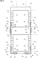
- Fig. 1 shows an embodiment of a car assembly 20 for a double-deck elevator 10.
- the car assembly 20 has a car frame 22, a first car 24, a second car 26, a push chain 30 and a drive device 40.
- the cars 24, 26 are arranged vertically one above the other in the car frame 22.
- the first cabin 24 is arranged below the second cabin 26.
- the first car 24 is accessible via a first entrance on a first floor 72
- the second car 26 is accessible via a second entrance on a second floor 74.
- a vertical distance between the cars 24, 26 can be adjusted using a control unit 70.
- the push chain 30 has a force-absorbing section 32, a first end 34 of the force-absorbing section 32, a second end 36 of the force-absorbing section 32 opposite the first end 34, and a remaining section 38.
- the push chain 30 can also be referred to as a first push chain 30.
- the force-absorbing section 32 can also be referred to as a first force-absorbing section 32.
- the push chain 30 has a plurality of connected chain links.
- the chain links When subjected to a compressive load, the chain links engage with one another in a form-fitting manner such that the force-absorbing section 32 is stable under the compressive load in a direction in which chain links of the push chain 30 can pivot relative to one another in the absence of a compressive load.
- the chain links can pivot relative to one another in a first lateral direction and are stable in directions perpendicular to the first lateral direction, in particular in a second lateral direction and a longitudinal direction of the push chain 30.
- the chain links Under the compressive load of the push chain 30, however, the chain links engage with one another in a form-fitting manner such that the push chain 30 is also stable in the first lateral direction in the region of the force-absorbing section 32.
- the remaining section 38 of the push chain 30 is arranged between the two cabins 24, 26.
- the remaining section 38 is arranged substantially horizontally.
- the remaining section 38 can, for example, rest on an upper side of the first cabin 24.
- the remaining section 38 is not subjected to pressure.
- the drive device 40 is coupled to the first cabin 24 and the push chain 32.
- the drive device 40 can also be referred to as the first drive device 40
- the drive device 40 has a motor and an output which is coupled to the push chain.
- the output is, for example, a gear that engages with the chain links of the push chain 30.
- the motor can be, for example, an electric motor.
- the drive device 40 has a housing. If necessary, the motor and/or the output can be arranged in or on the housing. Furthermore, a part of the force absorption section 32 and/or the remaining section 38 can be arranged in the housing and/or guided in the housing.
- Figure 1 In the embodiment shown, the drive device 40 is arranged on the first cabin 24. Alternatively, the drive device 40 can be arranged on the second cabin 26.
- the first car 24 has a plurality of fastening structures 41, via which it is firmly coupled to the car frame 22.
- the first car 24 is in the Figure 1
- the second car 26 is fixed relative to the car frame 22 by means of the fastening structures 41.
- the second car 26 has first brackets 42 that are fixedly connected to the rest of the second car 26.
- the second car 26 is coupled via the first brackets 42 to a first guide structure 44 arranged on the car frame 22 such that the second car 26 and in particular the first brackets 42 are movable in the vertical direction relative to the car frame 22.
- the weight of the second cabin 26 acts on the push chain 30.
- the second cabin 26 stands on the push chain 30. Due to the weight of the second cabin 26, the second cabin 26 exerts a compressive load on the push chain 30, in particular on the force-absorbing section 32. Due to this compressive load, the force-absorbing section 32 is stable in all directions, in particular in the first lateral direction.
- the compressive load is transmitted from the force-absorbing section 32 at the first end 34 to a first force-absorbing area 46.
- the drive device 40 in particular the output of the drive device 40, has the first force absorption region 46.
- the weight of the second cabin 26 is transmitted to the push chain 30 at the second end 36 in a second force absorption region 48.
- a floor of the second cabin 26 has the second force absorption area 48.
- the second car 26 can be displaced vertically relative to the first car 24 by means of the drive device 40 and the push chain 30.
- the drive device 40 can drive the push chain 30 such that the length of the force-absorbing section 32 changes, thereby changing the vertical position of the second car 26 relative to the first car 24.
- the push chain 30 can be used to push the second car 26 upwards or lowers relative to the car frame 22.
- the drive device 40 can have a control unit or be coupled to it, wherein the control unit is configured to control the drive device 40 depending on the vertical distance between the accesses of the corresponding floors. The control can be carried out by means of corresponding control signals.
- the drive device 40 can be configured such that, when the second car 26 is lowered relative to the car frame 20, the drive device 40 is driven by the push chain 30 as a generator and generates electrical energy.
- the potential energy released can be converted into electrical energy by means of the push chain 30 and the drive device 40 in generator mode.
- the electrical energy can be temporarily stored in an energy storage device (not shown in the figures) and reused at a later time, for example, to raise the second car 26.
- exactly one single push chain 30 is arranged.
- This single push chain 30 can, for example, be attached to the second cabin 26 in alignment with the center of gravity of the second cabin 26.
- two or more push chains for example four push chains, can be arranged to move the second cabin 26.
- the push chains can engage two diametrically opposite corner sections of the floor of the second cabin 26.
- corresponding second Force absorption areas 48 can be arranged at the diametrically opposite corner sections of the second cabin 26.
- Fig. 2 shows an embodiment of a car arrangement 20 which largely corresponds to that shown in Figure 1 Therefore, in order to avoid repetition, only the differences between the embodiment shown in Figure 2 shown embodiment and the one in Figure 1 shown embodiment.
- the elevator car assembly 20 has two push chains 30 and two drive devices 40.
- the elevator car assembly 20 can have more than two push chains 30 and corresponding drive devices 40.
- the push chains 30 are coupled at their respective first end 34 to the first force absorption region 46 and at their respective second end 36 to the second force absorption region 48, for example via the first brackets 42.
- the first force absorption region 46 is arranged on the elevator car frame 22 and the second force absorption region 48 is arranged on the second car 26, in particular on the first brackets 42.
- the drive devices 40 are arranged on the car frame 22. In this case, the drive devices 40 have the corresponding first force-absorbing regions 46.
- the drive devices 40 can be arranged on the second car 26, for example, on the first brackets 42. In this case, the drive devices 40 have the corresponding second force-absorbing regions 48.
- Fig. 3 shows an embodiment of a car assembly 20 which largely corresponds to one of the embodiments explained above. Therefore, in order to avoid repetition, only the differences between the embodiment shown in Figure 3 shown embodiment and the embodiments explained above.
- the first car 24, which is fixed with respect to the car frame 22, is arranged above the second car 26.
- the push chain 30 and the drive device 40 are arranged vertically between the car frame 22 and the second car 26.
- the first force absorption area 46 is arranged on the car frame 22, and the second force absorption area 48 is arranged on the second car 26.
- the drive device 40 is arranged on the second car 26 and has the second force-absorbing region 48.
- the drive device 40 can be arranged on the car frame 22 and have the first force-absorbing region 46.
- the remaining section 38 is guided horizontally along the second car 26, for example, in the housing of the drive device 40 (not shown in the figures).
- a single push chain 30 with a corresponding drive device 40 is arranged.
- two or more push chains 30 and corresponding drive devices 40 can be arranged vertically between the second car 26 and the car frame 22.
- the second force-absorbing region 48 is arranged on an underside of the second car 26.
- the second force-absorbing region(s) 48 can be arranged on the first brackets 42.
- Fig. 4 shows an embodiment of a car assembly 20 which largely corresponds to one of the embodiments explained above. Therefore, in order to avoid repetition, only the differences between the embodiment shown in Figure 4 shown embodiment and the embodiments explained above.
- the first car 24 is arranged above the second car 26 and coupled to the car frame 22 such that the first car 24 is displaceable in the vertical direction relative to the second car 26 and relative to the car frame 22.
- the first car 24 has second brackets 52 that are fixedly connected to the rest of the first car 24.
- the first car 24 is coupled via the second brackets 52 to a second guide structure 54 arranged on the car frame 22 such that the first car 24 is movable in the vertical direction relative to the car frame 22.
- Two additional push chains and two corresponding additional drive devices are arranged for vertically displacing the first cabin 24.
- the push chains 30 and drive devices 40 for vertically displacing the second cabin 26 can be designated as first push chains 30 and first drive devices 40, respectively.
- the further push chains and further drive devices for vertically displacing the first cabin 24 can be referred to as second push chains 60 and second drive devices 50, respectively.
- the second push chains 60 each have a second force-absorbing section 62, which engages a third force-absorbing region 56 at a first end 64 of the corresponding second force-absorbing section 62 and a fourth force-absorbing region 58 at a second end 66 of the corresponding second force-absorbing section 62.
- the fourth force-absorbing regions 58 are arranged on the first cabin 24, in particular on the second brackets 52.
- the fourth force-absorbing regions 58 can each be arranged on an underside of the first cabin 24.
- the third force-absorbing regions 56 can be arranged on the second cabin 26, for example on an upper side of the second cabin 26, for example such that the second push chains 60 and/or the second drive devices 50 are arranged in the vertical direction between the first cabin 24 and the second cabin 26.
- the second drive devices 50 are arranged on the car frame 22 and have the third force-absorbing regions 56.
- the second drive devices 50 can be arranged on the first car 24 and have the fourth force-absorbing regions 58.
- only one second push chain 60 and only one second drive device 50 or more than two second push chains 60 and correspondingly more second drive devices 50 can be arranged for vertically displacing the first cabin 24.
- the weight of the first cabin 24 acts on the second push chains 60.
- the first cabin 26 stands on the second push chains 60.
- the first cabin 24 exerts a compressive load on the second push chains 60, in particular on the second force-absorbing sections 62.
- the second force-absorbing sections 62 are stable in all directions, in particular in the first lateral direction.
- the compressive load is transmitted from the second force-absorbing sections 62 at the first ends 64 of the second force-absorbing sections 62 to the third force-absorbing regions 56.
- the invention is not limited to the given embodiments.
- the given embodiments can be combined with each other.
- the Figure 1 The embodiment shown is similar to that shown in Figure 2
- two or more push chains 30 and drive devices 40 can be arranged between the first cabin 24 and the second cabin 26.
- the drive device 40 can be arranged on the underside of the second cabin.
Landscapes
- Engineering & Computer Science (AREA)
- Civil Engineering (AREA)
- Mechanical Engineering (AREA)
- Structural Engineering (AREA)
- Cage And Drive Apparatuses For Elevators (AREA)
- Elevator Control (AREA)
- Maintenance And Inspection Apparatuses For Elevators (AREA)
Claims (12)
- Système de cabine d'ascenseur (20) pour un ascenseur à deux étages, dans lequel le système de cabine d'ascenseur (20) présente :- un cadre de cabine d'ascenseur (22) ;- une première cabine (24) qui est accouplée au cadre de cabine d'ascenseur (22) ;- une seconde cabine (26) qui est disposée sur le cadre de cabine d'ascenseur (22), au-dessus ou au-dessous de la première cabine (24), et qui est accouplée au cadre de cabine d'ascenseur (22) de sorte qu'elle peut être déplacée dans la direction verticale par rapport au cadre de cabine d'ascenseur (22) et par rapport à la première cabine (24),caractérisé en ce que
le système de cabine d'ascenseur (20) présente :- une chaîne de poussée (30) qui est accouplée par une première extrémité (34) d'une section d'absorption de force (32) de la chaîne de poussée (30) à la première cabine (24) ou au cadre de cabine d'ascenseur (22), est accouplée par une seconde extrémité (36) opposée de la section d'absorption de force (32) à la seconde cabine (26) et est disposée de sorte que la seconde cabine (26) exerce une charge de pression sur la section d'absorption de force (32) de la chaîne de poussée (30) en raison de la gravité ; et- un dispositif d'entraînement (40) qui est accouplé à la chaîne de poussée (30) et qui est réalisé pour déplacer la seconde cabine (26) dans la direction verticale par rapport à la première cabine (24) au moyen de la chaîne de poussée (30). - Système de cabine d'ascenseur (20) selon la revendication 1, dans lequel la chaîne de poussée (30) est réalisée de sorte que des maillons de chaîne de la chaîne de poussée (30) viennent en prise les uns dans les autres par complémentarité de forme sous une charge de pression, de telle sorte que la section d'absorption de force (32) de la chaîne de poussée (30) est stable sous la charge de pression dans une direction dans laquelle des maillons de chaîne de la chaîne de poussée (30) peuvent pivoter les uns par rapport aux autres en l'absence de charge de pression.
- Système de cabine d'ascenseur (20) selon l'une des revendications précédentes, dans lequel le dispositif d'entraînement (40) est réalisé et accouplé à la chaîne de poussée (30) de sorte que, lors d'un déplacement de la seconde cabine (26) en direction de la gravité, la chaîne de poussée (30) entraîne par générateur le dispositif d'entraînement (40).
- Système de cabine d'ascenseur (20) selon l'une des revendications précédentes, dans lequel le dispositif d'entraînement (40) présente un moteur et un entraînement qui est disposé sur un arbre du moteur et vient en prise avec la chaîne de poussée (30).
- Système de cabine d'ascenseur (20) selon l'une des revendications précédentes,dans lequel le dispositif d'entraînement (40) est disposé sur la seconde cabine (26) ; ou,le dispositif d'entraînement (40) est disposé sur la première cabine (24) et la chaîne de poussée (30) est accouplée à la première cabine (24) ; oule dispositif d'entraînement (40) est disposé sur le cadre de cabine d'ascenseur (22) et la chaîne de poussée (30) est accouplée au cadre de cabine d'ascenseur (22).
- Système de cabine d'ascenseur (20) selon l'une des revendications précédentes, dans lequel la chaîne de poussée (30) est disposée de sorte qu'une section résiduelle (38) de la chaîne de poussée (30), laquelle section résiduelle n'est pas la section d'absorption de force (32), est disposée entre les cabines (24 ; 26).
- Système de cabine d'ascenseur (20) selon la revendication 6, dans lequel la chaîne de poussée (30) est disposée de sorte que la section résiduelle (38) de la chaîne de poussée (30) s'étend au moins partiellement dans la direction horizontale.
- Système de cabine d'ascenseur (20) selon l'une des revendications précédentes, dans lequel, si la chaîne de poussée (30) est accouplée à la première cabine (24), la première cabine (24) présente une première zone d'absorption de force (46), ou, si la chaîne de poussée (30) est accouplée au cadre de cabine d'ascenseur (22), le cadre de cabine d'ascenseur (22) présente la première zone d'absorption de force (46) ;la seconde cabine (26) présente une seconde zone d'absorption de force (48) ;la chaîne de poussée (30) est accouplée par la première extrémité (34) de la section d'absorption de force (32) à la première zone d'absorption de force (46) et est accouplée par la seconde extrémité (36) de la section d'absorption de force (32) à la seconde zone d'absorption de force (48) ;la section d'absorption de force (32) s'étend de la première zone d'absorption de force (46) à la seconde zone d'absorption de force (48) ;une distance verticale entre les deux cabines (24 ; 26) dépend d'une longueur de la section d'absorption de force (32) ; etle dispositif d'entraînement (40) est réalisé pour déplacer la chaîne de poussée (30) pour le déplacement de la seconde cabine (26) dans la direction verticale, de sorte que la longueur de la section d'absorption de force (32) varie.
- Système de cabine d'ascenseur (20) selon l'une des revendications précédentes, dans lequel la première cabine (24) est accouplée au cadre de cabine d'ascenseur (22) de sorte qu'elle est disposée de manière à pouvoir se déplacer dans la direction verticale par rapport au cadre de cabine d'ascenseur (22),le système de cabine d'ascenseur (20) présente une autre chaîne de poussée (60) qui est accouplée à la première cabine (24) et au cadre de cabine d'ascenseur (22),le système de cabine d'ascenseur (20) présente un autre dispositif d'entraînement (50) qui est accouplé à l'autre chaîne de poussée (60), etl'autre dispositif d'entraînement (50) est réalisé pour déplacer la première cabine (24) dans la direction verticale par rapport au cadre de cabine d'ascenseur (22) au moyen de l'autre chaîne de poussée (60).
- Système de cabine d'ascenseur (20) selon l'une des revendications précédentes, dans lequel le système de cabine d'ascenseur (20) présente exactement une seule chaîne de poussée (30) pour le déplacement vertical de la seconde cabine (26).
- Système de cabine d'ascenseur (20) selon la revendication 10, dans lequel la chaîne de poussée (30) est fixée à la seconde cabine (26) de manière à être alignée avec le centre de gravité de la seconde cabine (26).
- Ascenseur à double cabine (10), présentant :un système de cabine d'ascenseur (20) selon l'une des revendications précédentes ; etun appareil de commande (70) qui est configuré pour commander le dispositif d'entraînement (40) du système de cabine d'ascenseur (20) en fonction d'une distance interétage entre un premier étage (72) et un second étage (74) de sorte que, dans la position d'arrêt du système de cabine d'ascenseur (20), la première cabine (24) est accessible par l'intermédiaire du premier étage (72) et la seconde cabine (26) est accessible par l'intermédiaire du second étage (74).
Applications Claiming Priority (2)
| Application Number | Priority Date | Filing Date | Title |
|---|---|---|---|
| EP21165085 | 2021-03-26 | ||
| PCT/EP2022/056023 WO2022200046A1 (fr) | 2021-03-26 | 2022-03-09 | Agencement de cabine d'ascenseur pour ascenseur à cabines superposées et ascenseur à cabines superposées |
Publications (2)
| Publication Number | Publication Date |
|---|---|
| EP4313833A1 EP4313833A1 (fr) | 2024-02-07 |
| EP4313833B1 true EP4313833B1 (fr) | 2025-04-30 |
Family
ID=75252337
Family Applications (1)
| Application Number | Title | Priority Date | Filing Date |
|---|---|---|---|
| EP22711242.2A Active EP4313833B1 (fr) | 2021-03-26 | 2022-03-09 | Agencement de cabine pour un ascenseur à double étage et ascenseur à double étage |
Country Status (6)
| Country | Link |
|---|---|
| US (1) | US12291426B2 (fr) |
| EP (1) | EP4313833B1 (fr) |
| CN (1) | CN117083237A (fr) |
| AU (1) | AU2022245073B2 (fr) |
| CA (1) | CA3214295A1 (fr) |
| WO (1) | WO2022200046A1 (fr) |
Family Cites Families (9)
| Publication number | Priority date | Publication date | Assignee | Title |
|---|---|---|---|---|
| JP4303842B2 (ja) * | 1999-08-10 | 2009-07-29 | 東芝エレベータ株式会社 | ダブルデッキエレベータ |
| CN1239376C (zh) * | 2000-11-08 | 2006-02-01 | 三菱电机株式会社 | 双层电梯的轿厢装置 |
| FI119240B (fi) * | 2005-12-29 | 2008-09-15 | Kone Corp | Hissijärjestelmä ja laitteisto kaksoiskorihissin korivälin säätämiseksi |
| EP2468674A1 (fr) * | 2010-12-22 | 2012-06-27 | Inventio AG | Installation d'ascenseur à biplan |
| DE102013110790A1 (de) | 2013-09-30 | 2015-04-02 | Thyssenkrupp Elevator Ag | Aufzuganlage |
| WO2016006056A1 (fr) * | 2014-07-09 | 2016-01-14 | 三菱電機株式会社 | Système d'ascenseur |
| CN104925622A (zh) * | 2015-06-23 | 2015-09-23 | 上海爱登堡电梯(宜昌)有限公司 | 可调式双层电梯 |
| FR3072374B1 (fr) | 2017-10-17 | 2022-12-30 | Serapid France | Dispositif elevatoire par poussee |
| US10899580B2 (en) | 2018-01-15 | 2021-01-26 | Otis Elevator Company | Elevator cab suspension assembly for a double deck elevator |
-
2022
- 2022-03-09 CN CN202280024565.6A patent/CN117083237A/zh active Pending
- 2022-03-09 US US18/551,199 patent/US12291426B2/en active Active
- 2022-03-09 CA CA3214295A patent/CA3214295A1/fr active Pending
- 2022-03-09 AU AU2022245073A patent/AU2022245073B2/en active Active
- 2022-03-09 WO PCT/EP2022/056023 patent/WO2022200046A1/fr not_active Ceased
- 2022-03-09 EP EP22711242.2A patent/EP4313833B1/fr active Active
Also Published As
| Publication number | Publication date |
|---|---|
| AU2022245073B2 (en) | 2025-06-05 |
| CN117083237A (zh) | 2023-11-17 |
| EP4313833A1 (fr) | 2024-02-07 |
| US20240300781A1 (en) | 2024-09-12 |
| US12291426B2 (en) | 2025-05-06 |
| AU2022245073A1 (en) | 2023-10-12 |
| WO2022200046A1 (fr) | 2022-09-29 |
| CA3214295A1 (fr) | 2022-09-29 |
Similar Documents
| Publication | Publication Date | Title |
|---|---|---|
| EP2150663B1 (fr) | Dispositif de rangement pour véhicules à moteur | |
| EP2398729B1 (fr) | Installation d'ascenseur présentant un mobile à plusieurs étages | |
| EP2185457B1 (fr) | Porte de cabine d'ascenseur mobile sur toute sa longueur verticale pour ouvrir la cabine au choix vers le haut ou vers le bas | |
| EP3668810B1 (fr) | Système élévateur | |
| EP1367018B1 (fr) | Ascenseur comprenant plusiers cabines auto-motrice et au moins trois gaines d'ascenseur disposé côte à côte | |
| DE4028484C2 (fr) | ||
| EP3550095A1 (fr) | Système de stationnement | |
| EP2512969B1 (fr) | Installation d'ascenseur à double cabine | |
| EP4038004B1 (fr) | Cabine pour un ascenseur à double étage | |
| EP3732124B1 (fr) | Dispositif pour le stationnement de véhicules | |
| DE3714053C2 (de) | Aufzug für Personentransport | |
| EP4313833B1 (fr) | Agencement de cabine pour un ascenseur à double étage et ascenseur à double étage | |
| EP3580111B1 (fr) | Suspension de châssis | |
| DE3720239C2 (fr) | ||
| DE102011018618B4 (de) | Einstieghilfe | |
| EP2468674A1 (fr) | Installation d'ascenseur à biplan | |
| EP3924285B1 (fr) | Système d'ascenseur | |
| EP1479636A1 (fr) | Amortisseur qui peut créer une zone d' inspection sûre pour ascenseur | |
| EP3621909B1 (fr) | Systeme d'ascenseure avec deux puits | |
| EP3645443B1 (fr) | Système d'ascenseur | |
| DE3221415A1 (de) | Aufzugseinrichtung | |
| DE69826819T2 (de) | Aufzug mit an Bord eingebauter Antriebseinrichtung | |
| DE102011109900B3 (de) | Schrägaufzug insbesondere für Rollstühle mit faltbarer Plattform | |
| DE2608343C2 (de) | Hebebühne | |
| EP1726560A1 (fr) | Table élévatrice à ciseaux |
Legal Events
| Date | Code | Title | Description |
|---|---|---|---|
| STAA | Information on the status of an ep patent application or granted ep patent |
Free format text: STATUS: UNKNOWN |
|
| STAA | Information on the status of an ep patent application or granted ep patent |
Free format text: STATUS: THE INTERNATIONAL PUBLICATION HAS BEEN MADE |
|
| PUAI | Public reference made under article 153(3) epc to a published international application that has entered the european phase |
Free format text: ORIGINAL CODE: 0009012 |
|
| STAA | Information on the status of an ep patent application or granted ep patent |
Free format text: STATUS: REQUEST FOR EXAMINATION WAS MADE |
|
| 17P | Request for examination filed |
Effective date: 20230830 |
|
| AK | Designated contracting states |
Kind code of ref document: A1 Designated state(s): AL AT BE BG CH CY CZ DE DK EE ES FI FR GB GR HR HU IE IS IT LI LT LU LV MC MK MT NL NO PL PT RO RS SE SI SK SM TR |
|
| DAV | Request for validation of the european patent (deleted) | ||
| DAX | Request for extension of the european patent (deleted) | ||
| GRAP | Despatch of communication of intention to grant a patent |
Free format text: ORIGINAL CODE: EPIDOSNIGR1 |
|
| STAA | Information on the status of an ep patent application or granted ep patent |
Free format text: STATUS: GRANT OF PATENT IS INTENDED |
|
| GRAS | Grant fee paid |
Free format text: ORIGINAL CODE: EPIDOSNIGR3 |
|
| INTG | Intention to grant announced |
Effective date: 20250109 |
|
| GRAA | (expected) grant |
Free format text: ORIGINAL CODE: 0009210 |
|
| STAA | Information on the status of an ep patent application or granted ep patent |
Free format text: STATUS: THE PATENT HAS BEEN GRANTED |
|
| AK | Designated contracting states |
Kind code of ref document: B1 Designated state(s): AL AT BE BG CH CY CZ DE DK EE ES FI FR GB GR HR HU IE IS IT LI LT LU LV MC MK MT NL NO PL PT RO RS SE SI SK SM TR |
|
| REG | Reference to a national code |
Ref country code: CH Ref legal event code: EP Ref country code: GB Ref legal event code: FG4D Free format text: NOT ENGLISH |
|
| REG | Reference to a national code |
Ref country code: IE Ref legal event code: FG4D Free format text: LANGUAGE OF EP DOCUMENT: GERMAN |
|
| REG | Reference to a national code |
Ref country code: DE Ref legal event code: R096 Ref document number: 502022003769 Country of ref document: DE |
|
| REG | Reference to a national code |
Ref country code: NL Ref legal event code: MP Effective date: 20250430 |
|
| PG25 | Lapsed in a contracting state [announced via postgrant information from national office to epo] |
Ref country code: PT Free format text: LAPSE BECAUSE OF FAILURE TO SUBMIT A TRANSLATION OF THE DESCRIPTION OR TO PAY THE FEE WITHIN THE PRESCRIBED TIME-LIMIT Effective date: 20250901 Ref country code: FI Free format text: LAPSE BECAUSE OF FAILURE TO SUBMIT A TRANSLATION OF THE DESCRIPTION OR TO PAY THE FEE WITHIN THE PRESCRIBED TIME-LIMIT Effective date: 20250430 Ref country code: ES Free format text: LAPSE BECAUSE OF FAILURE TO SUBMIT A TRANSLATION OF THE DESCRIPTION OR TO PAY THE FEE WITHIN THE PRESCRIBED TIME-LIMIT Effective date: 20250430 |
|
| REG | Reference to a national code |
Ref country code: LT Ref legal event code: MG9D |
|
| PG25 | Lapsed in a contracting state [announced via postgrant information from national office to epo] |
Ref country code: NO Free format text: LAPSE BECAUSE OF FAILURE TO SUBMIT A TRANSLATION OF THE DESCRIPTION OR TO PAY THE FEE WITHIN THE PRESCRIBED TIME-LIMIT Effective date: 20250730 Ref country code: GR Free format text: LAPSE BECAUSE OF FAILURE TO SUBMIT A TRANSLATION OF THE DESCRIPTION OR TO PAY THE FEE WITHIN THE PRESCRIBED TIME-LIMIT Effective date: 20250731 |
|
| PG25 | Lapsed in a contracting state [announced via postgrant information from national office to epo] |
Ref country code: NL Free format text: LAPSE BECAUSE OF FAILURE TO SUBMIT A TRANSLATION OF THE DESCRIPTION OR TO PAY THE FEE WITHIN THE PRESCRIBED TIME-LIMIT Effective date: 20250430 Ref country code: PL Free format text: LAPSE BECAUSE OF FAILURE TO SUBMIT A TRANSLATION OF THE DESCRIPTION OR TO PAY THE FEE WITHIN THE PRESCRIBED TIME-LIMIT Effective date: 20250430 |
|
| PG25 | Lapsed in a contracting state [announced via postgrant information from national office to epo] |
Ref country code: BG Free format text: LAPSE BECAUSE OF FAILURE TO SUBMIT A TRANSLATION OF THE DESCRIPTION OR TO PAY THE FEE WITHIN THE PRESCRIBED TIME-LIMIT Effective date: 20250430 |
|
| PG25 | Lapsed in a contracting state [announced via postgrant information from national office to epo] |
Ref country code: HR Free format text: LAPSE BECAUSE OF FAILURE TO SUBMIT A TRANSLATION OF THE DESCRIPTION OR TO PAY THE FEE WITHIN THE PRESCRIBED TIME-LIMIT Effective date: 20250430 |
|
| PG25 | Lapsed in a contracting state [announced via postgrant information from national office to epo] |
Ref country code: RS Free format text: LAPSE BECAUSE OF FAILURE TO SUBMIT A TRANSLATION OF THE DESCRIPTION OR TO PAY THE FEE WITHIN THE PRESCRIBED TIME-LIMIT Effective date: 20250731 |
|
| PG25 | Lapsed in a contracting state [announced via postgrant information from national office to epo] |
Ref country code: IS Free format text: LAPSE BECAUSE OF FAILURE TO SUBMIT A TRANSLATION OF THE DESCRIPTION OR TO PAY THE FEE WITHIN THE PRESCRIBED TIME-LIMIT Effective date: 20250830 |
|
| PG25 | Lapsed in a contracting state [announced via postgrant information from national office to epo] |
Ref country code: LV Free format text: LAPSE BECAUSE OF FAILURE TO SUBMIT A TRANSLATION OF THE DESCRIPTION OR TO PAY THE FEE WITHIN THE PRESCRIBED TIME-LIMIT Effective date: 20250430 |
|
| PG25 | Lapsed in a contracting state [announced via postgrant information from national office to epo] |
Ref country code: SM Free format text: LAPSE BECAUSE OF FAILURE TO SUBMIT A TRANSLATION OF THE DESCRIPTION OR TO PAY THE FEE WITHIN THE PRESCRIBED TIME-LIMIT Effective date: 20250430 Ref country code: DK Free format text: LAPSE BECAUSE OF FAILURE TO SUBMIT A TRANSLATION OF THE DESCRIPTION OR TO PAY THE FEE WITHIN THE PRESCRIBED TIME-LIMIT Effective date: 20250430 |
|
| PG25 | Lapsed in a contracting state [announced via postgrant information from national office to epo] |
Ref country code: CZ Free format text: LAPSE BECAUSE OF FAILURE TO SUBMIT A TRANSLATION OF THE DESCRIPTION OR TO PAY THE FEE WITHIN THE PRESCRIBED TIME-LIMIT Effective date: 20250430 |
|
| PG25 | Lapsed in a contracting state [announced via postgrant information from national office to epo] |
Ref country code: EE Free format text: LAPSE BECAUSE OF FAILURE TO SUBMIT A TRANSLATION OF THE DESCRIPTION OR TO PAY THE FEE WITHIN THE PRESCRIBED TIME-LIMIT Effective date: 20250430 |
|
| PG25 | Lapsed in a contracting state [announced via postgrant information from national office to epo] |
Ref country code: SK Free format text: LAPSE BECAUSE OF FAILURE TO SUBMIT A TRANSLATION OF THE DESCRIPTION OR TO PAY THE FEE WITHIN THE PRESCRIBED TIME-LIMIT Effective date: 20250430 |
|
| PG25 | Lapsed in a contracting state [announced via postgrant information from national office to epo] |
Ref country code: IT Free format text: LAPSE BECAUSE OF FAILURE TO SUBMIT A TRANSLATION OF THE DESCRIPTION OR TO PAY THE FEE WITHIN THE PRESCRIBED TIME-LIMIT Effective date: 20250430 |
|
| REG | Reference to a national code |
Ref country code: DE Ref legal event code: R097 Ref document number: 502022003769 Country of ref document: DE |
|
| PLBE | No opposition filed within time limit |
Free format text: ORIGINAL CODE: 0009261 |
|
| STAA | Information on the status of an ep patent application or granted ep patent |
Free format text: STATUS: NO OPPOSITION FILED WITHIN TIME LIMIT |
|
| REG | Reference to a national code |
Ref country code: CH Ref legal event code: L10 Free format text: ST27 STATUS EVENT CODE: U-0-0-L10-L00 (AS PROVIDED BY THE NATIONAL OFFICE) Effective date: 20260311 |
|
| 26N | No opposition filed |
Effective date: 20260202 |
|
| PGFP | Annual fee paid to national office [announced via postgrant information from national office to epo] |
Ref country code: AT Payment date: 20260301 Year of fee payment: 5 |