EP4314475B1 - Grössenbestimmung eines axialen gewindespiels - Google Patents
Grössenbestimmung eines axialen gewindespiels Download PDFInfo
- Publication number
- EP4314475B1 EP4314475B1 EP22715127.1A EP22715127A EP4314475B1 EP 4314475 B1 EP4314475 B1 EP 4314475B1 EP 22715127 A EP22715127 A EP 22715127A EP 4314475 B1 EP4314475 B1 EP 4314475B1
- Authority
- EP
- European Patent Office
- Prior art keywords
- male
- female
- threaded
- epcoat
- thread
- Prior art date
- Legal status (The legal status is an assumption and is not a legal conclusion. Google has not performed a legal analysis and makes no representation as to the accuracy of the status listed.)
- Active
Links
Images

Classifications
-
- E—FIXED CONSTRUCTIONS
- E21—EARTH OR ROCK DRILLING; MINING
- E21B—EARTH OR ROCK DRILLING; OBTAINING OIL, GAS, WATER, SOLUBLE OR MELTABLE MATERIALS OR A SLURRY OF MINERALS FROM WELLS
- E21B17/00—Drilling rods or pipes; Flexible drill strings; Kellies; Drill collars; Sucker rods; Cables; Casings; Tubings
- E21B17/02—Couplings; joints
- E21B17/04—Couplings; joints between rod or the like and bit or between rod and rod or the like
- E21B17/042—Threaded
-
- F—MECHANICAL ENGINEERING; LIGHTING; HEATING; WEAPONS; BLASTING
- F16—ENGINEERING ELEMENTS AND UNITS; GENERAL MEASURES FOR PRODUCING AND MAINTAINING EFFECTIVE FUNCTIONING OF MACHINES OR INSTALLATIONS; THERMAL INSULATION IN GENERAL
- F16L—PIPES; JOINTS OR FITTINGS FOR PIPES; SUPPORTS FOR PIPES, CABLES OR PROTECTIVE TUBING; MEANS FOR THERMAL INSULATION IN GENERAL
- F16L15/00—Screw-threaded joints; Forms of screw-threads for such joints
- F16L15/006—Screw-threaded joints; Forms of screw-threads for such joints with straight threads
- F16L15/009—Screw-threaded joints; Forms of screw-threads for such joints with straight threads with axial sealings having at least one plastically deformable sealing surface
-
- F—MECHANICAL ENGINEERING; LIGHTING; HEATING; WEAPONS; BLASTING
- F16—ENGINEERING ELEMENTS AND UNITS; GENERAL MEASURES FOR PRODUCING AND MAINTAINING EFFECTIVE FUNCTIONING OF MACHINES OR INSTALLATIONS; THERMAL INSULATION IN GENERAL
- F16L—PIPES; JOINTS OR FITTINGS FOR PIPES; SUPPORTS FOR PIPES, CABLES OR PROTECTIVE TUBING; MEANS FOR THERMAL INSULATION IN GENERAL
- F16L15/00—Screw-threaded joints; Forms of screw-threads for such joints
- F16L15/08—Screw-threaded joints; Forms of screw-threads for such joints with supplementary elements
-
- F—MECHANICAL ENGINEERING; LIGHTING; HEATING; WEAPONS; BLASTING
- F16—ENGINEERING ELEMENTS AND UNITS; GENERAL MEASURES FOR PRODUCING AND MAINTAINING EFFECTIVE FUNCTIONING OF MACHINES OR INSTALLATIONS; THERMAL INSULATION IN GENERAL
- F16L—PIPES; JOINTS OR FITTINGS FOR PIPES; SUPPORTS FOR PIPES, CABLES OR PROTECTIVE TUBING; MEANS FOR THERMAL INSULATION IN GENERAL
- F16L58/00—Protection of pipes or pipe fittings against corrosion or incrustation
- F16L58/02—Protection of pipes or pipe fittings against corrosion or incrustation by means of internal or external coatings
- F16L58/04—Coatings characterised by the materials used
- F16L58/08—Coatings characterised by the materials used by metal
-
- F—MECHANICAL ENGINEERING; LIGHTING; HEATING; WEAPONS; BLASTING
- F16—ENGINEERING ELEMENTS AND UNITS; GENERAL MEASURES FOR PRODUCING AND MAINTAINING EFFECTIVE FUNCTIONING OF MACHINES OR INSTALLATIONS; THERMAL INSULATION IN GENERAL
- F16L—PIPES; JOINTS OR FITTINGS FOR PIPES; SUPPORTS FOR PIPES, CABLES OR PROTECTIVE TUBING; MEANS FOR THERMAL INSULATION IN GENERAL
- F16L15/00—Screw-threaded joints; Forms of screw-threads for such joints
- F16L15/001—Screw-threaded joints; Forms of screw-threads for such joints with conical threads
-
- F—MECHANICAL ENGINEERING; LIGHTING; HEATING; WEAPONS; BLASTING
- F16—ENGINEERING ELEMENTS AND UNITS; GENERAL MEASURES FOR PRODUCING AND MAINTAINING EFFECTIVE FUNCTIONING OF MACHINES OR INSTALLATIONS; THERMAL INSULATION IN GENERAL
- F16L—PIPES; JOINTS OR FITTINGS FOR PIPES; SUPPORTS FOR PIPES, CABLES OR PROTECTIVE TUBING; MEANS FOR THERMAL INSULATION IN GENERAL
- F16L15/00—Screw-threaded joints; Forms of screw-threads for such joints
- F16L15/06—Screw-threaded joints; Forms of screw-threads for such joints characterised by the shape of the screw-thread
Definitions
- the invention relates to steel components or conduits in the field of oil and gas, energy or storage, for use such as the exploitation of wells or the transport of hydrocarbons, the transport or storage of hydrogen, geothermal energy or carbon capture.
- component means any element, accessory or conduit, used to drill or exploit a well and comprising at least one connection or connector or even a threaded end, and intended to be assembled by a thread to another component to constitute with this other component a threaded joint.
- the component can be for example a tube or a tubular element of relatively great length (in particular around ten meters in length), for example a tube, or a tubular sleeve of a few tens of centimeters in length, or even a accessory for these tubular elements (suspension device or “hanger”, section change piece or “cross-over”, safety valve, connector for drilling rod or “tool joint”, “sub”, and the like).
- Components or conduits have threaded ends. These threaded ends are complementary allowing the connection of two male (“Pin”) and female (“Box”) tubular elements between them. So there is a male threaded end and a female threaded end. So-called premium or semi-premium threaded ends generally have at least one abutment surface.
- a first stop can be formed by two surfaces of two threaded ends, oriented in a substantially radial manner, configured so as to be in contact with one another after screwing the threaded ends together or during load stresses. compression. The stops generally have negative angles to the main axis of the connections. Intermediate stops are also known on joints comprising at least two thread stages.
- the threaded end, the surface of stop as well as a sealing surface can form an assembly called a lip.
- a lip with a thread oriented towards the outside of the tube, that is to say a male lip, and a lip with a thread oriented towards the inside of the tube, that is to say a female lip.
- Machining a tube to produce its thread implies the existence of a thread pitch.
- the notion of thread pitch must be understood in light of ISO 5408:2009 which concerns the definition of threads.
- the thread pitch must be controlled in order to avoid assembly problems and use of a joint, between the male thread and the corresponding female thread.
- the applicant was able to identify and establish in a surprising manner that the accumulation of pitch errors which may be individually acceptable, can contribute to an offset of the thread flanks over the entire thread.
- This accumulation and/or this shift when it exceeds a certain threshold and when it is opposed on a male and female tubular element creates a pitch mismatch, the latter has the consequence of generating axial interference or a docking problem between thread flanks.
- This axial interference or docking problem can cause excessive stress on one or more places on the thread due to the compression of two male and female thread teeth.
- This excessive constraint is capable of generating docking between threads at too high a number of screwing turns, to the detriment of screwing for which it is no longer possible to ensure the correct positioning of the male part with respect to the female part.
- a leak can cause considerable economic or even environmental consequences, for example when a leak occurs in a hydrocarbon well during its operation.
- FR2952993 A1 discloses a threaded joint comprising respectively male and female threads having an axial play remaining in the connected state between the engagement flanks of the male and female threads, and the distal surface of the male end and/or the female end being brought into axial abutment contact against a corresponding abutment surface.
- the document discloses axial clearance in the range of 0.002 mm to 1 mm, where the choice of axial clearance in the connected state can be guided by the desired grease volume, flank angle and machining tolerances.
- the invention makes it possible to resolve all of the problems mentioned above.
- the invention proposes a configuration capable of overcoming the consequences of pitch errors and in particular their accumulation in the thread, while ensuring an absence of axial interference or docking problems as well as a waterproofing.
- a joint according to the invention has an axial thread clearance (TAG) which respects a minimum threshold from which it is ensured to compensate for the effect of any offset of the thread resulting from an accumulation of error of not.
- TAG axial thread clearance
- axial thread clearance or “Threaded Axial Gap” (TAG) is meant the distance separating an engagement flank of a male thread tooth and an engagement flank of a female thread tooth facing the flank of the thread. engagement of the male thread tooth, which can be expressed in mm. This axial thread clearance is measured at half the height of the male tooth.
- pitch error we mean the offset which results from the comparison between a real pitch, that is to say the pitch measured on a produced part and a pitch on the plan, that is to say the pitch initially defined on the product plan.
- pitch error means any pitch error per thread that is sufficiently small and tolerable to be validated when checking the thread after machining, the reference values being defined on a drawing and/or by standard.
- pitch separation we mean the difference between the cumulative pitch error on the male thread and the cumulative pitch error on the female thread.
- this equation also makes it possible to ensure a controlled level of screwing.
- the value of the pitch separation tolerance is between 0.040 and 0.080 mm, preferably between 0.048 and 0.072 mm.
- the step error can be measured by a conventional control device, for example described in API 5B1. Indeed, below the tolerance we will be forced to use more expensive devices whose measurement results are not necessarily assured. It is not desirable to have a tolerance value greater than 0.080 mm.
- sealing performance we mean the resistance of the connection to combined external/internal pressure and traction/compression stresses. Sealing can be liquid or gas.
- a joint according to the invention is more robust under stresses which require compression.
- the axial thread clearance TAG is between two values TAGmin and TAGmax such that: TAGmin ⁇ TAGmax
- the tubular threaded joint (1) is characterized in that at least one of the male threaded portions (4) or female threaded portions (5) comprises an anti-corrosive and/or lubricating coating and in that the value of the thickness of the anticorrosive and/or lubricating coating (10) Epcoat is greater than zero.
- a solid anti-corrosive and/or lubricating coating to the thread increases the risk of unwanted axial interference.
- the thickness of a solid coating can contribute to increasing the contact pressure on the sides of a thread, increasing the risk of weakening or plasticization. The invention then allows screwing without risk of weakening or additional plasticization of a connection due to a coating in a thread.
- the tubular threaded joint is characterized in that the maximum value of the thickness of an anticorrosive and/or lubricating coating Epcoat max is equal to 0.0075 mm.
- the configuration can integrate a wide variety of solid anti-corrosive and/or lubricating coatings, which eliminates a risk linked to pitch separation up to a maximum value of 0.0075 mm.
- the anticorrosive and/or lubricating coating comprises a layer comprising Zinc and Nickel.
- FIG. 1 describes a tubular threaded joint (1) according to the invention comprising a male tubular element (2) comprising a male threaded portion (4), a male sealing surface (28) as well as a male stop (24), and a female tubular element (3) comprising a female threaded portion (5), a female sealing surface (29) and a female stop (25).
- Said male (4) and female (5) threaded portions respectively comprising several male (6) and female (7) thread teeth coming from the same threading helix.
- the definition of a thread helix is given in ISO 5408.
- a male thread tooth (6) comprises a male engaging flank (14) and a male carrying flank (12).
- a female thread tooth (7) includes a female engagement flank (15) and a female carrying flank (13).
- the joint of the figure 1 is shown during its use during a tensile effort, for example subjected to the weight of the column in vertical tension, in the direction of the arrow.
- it is the male (12) and female (13) supporting sides which are in contact.
- the male (14) and female (15) engagement flanks are not necessarily in contact and delimit a space which consists of an axial clearance of “TAG” threads.
- the stops and the sealing surfaces can be in contact.
- TAG thread axial clearance
- FIG. 2 describes a tubular threaded joint (1) according to the invention during aggravated use, for example when there is a temperature difference which induces compressive forces at the level of the threaded joint.
- the connection will tend to deform under the action of said compressive forces.
- it is the male engagement flanks (14) which are in contact with the female engagement flanks (15).
- the stress on the male (28) and female (29) sealing surfaces and the male (24) and female (25) stops which were already in contact will increase. There is increased interference at the male (28) and female (29) sealing surfaces and the male (24) and female (25) stops.
- TAG thread axial clearance
- TAGmin corresponds to a minimum threshold value from which the effect of any thread offset resulting from an accumulation of pitch error is canceled, this accumulation can also come from several individually acceptable pitch errors.
- the accumulation of step errors and the resulting aggravation is illustrated in the Figure 12 .
- the minimum clearance TAGmin is determined according to the minimum value of the pitch separation tolerance ITmin, the minimum value of the axial length of male thread LFpinmin, the minimum value of the axial length of female thread LFboxmin, the minimum value of the distance of the male pitch tolerance Dpinmin, and finally the minimum value of the distance of the female pitch tolerance Dboxmin.
- the threaded joint may include a coating on the threads and therefore the additional parameter of Epcoat coating thickness must be taken into account. In the case of the Figure 3 there is no coating and therefore Epcoat is 0.
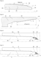
- axial length of male thread LFpinmin or female LFboxmin we mean the total length of the thread along the thread axis of the tube. This total thread length is measured from the root of the first tooth to the root of the last tooth, as shown in figures 4 and 5 .
- the distance of the male pitch tolerance Dpinmin or female Dboxmin we mean the length over which the pitch is controlled, that is to say the total length of the perfect threads.
- a perfect net can be defined as opposed to an imperfect net, that is to say a net whose height is not complete. We also speak of a vanishing net for an imperfect net.
- the tolerance of a pitch error means the acceptable deviations of pitch error from the nominal plane.
- pitch unmarrying tolerance we mean the difference between the male pitch error tolerance and the female pitch error tolerance.
- pitch we mean the distance between two successive load-bearing flanks as defined by ISO 5408.
- the value of the pitch separation tolerance ITmin can be between 0.040 and 0.080 mm, preferably between 0.048 and 0.072 mm.
- the pitch error can be measured by a conventional control device, for example described in API 5B1. Indeed, below the minimum value it is necessary to resort to more expensive devices whose measurement result is not necessarily assured. Above the maximum value, the minimum value of the TAG min thread axial clearance is too large.
- TAGmin value depends indirectly on the axial thread length.
- FIG. 4 shows a male end (20) according to the invention in a longitudinal sectional view, comprising a male lip (22) and a metal body (18).
- Said male lip comprises a male threaded portion (4), a male abutment surface (24) as well as a male sealing surface (28).
- the male threaded portion (4) comprises several male thread teeth (6) which extend successively along a thread root line Y.
- the thread axis is parallel to the axis X which extends longitudinally .
- the male or female pitch tolerance distance corresponds to the length over which the pitch is controlled, i.e. the total length of the perfect threads.
- a perfect net can be defined in opposition to an imperfect net, that is to say a net whose height is not complete. We also speak of a vanishing net for an imperfect net.
- the pitch tolerance distance is defined by Dpinmin.
- FIG. 5 describes a female end (21) according to the invention in a longitudinal sectional view comprising a female lip (23) and a metal body (18).
- Said female lip comprises a female threaded portion (5), a female abutment surface (25) as well as a female sealing surface (29).
- the female threaded portion (5) comprises several thread teeth (7) which extend successively along and from a thread root line Y.
- the thread axis is parallel to the axis extends longitudinally.
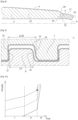
- FIG. 6 shows schematically, in a longitudinal sectional view, a tubular threaded joint (61) according to the state of the art with representation of constraints by finite element analysis (FEA).
- the tubular threaded joint (61) comprises a male tubular element (62) comprising a male threaded portion (64), a male sealing surface (28) as well as a male stop (24), and a female tubular element (63 ) comprising a female threaded portion (65), a female sealing surface (29) as well as a female stop (25).
- the joint includes an axial thread clearance i.e. a TAG of 0.250 mm for a connection with an outside diameter (OD) of 139.7 mm. Referring to table 2 below, a clearance of 0.250mm is greater than the TAGmax value indicated for a connection of 139.7mm nominal external diameter.
- the dark areas of the Figure 6 correspond to zones of plasticization resulting from mechanical compressions as could be visualized on a finite element analysis (FEA). It can be observed on the Figure 6 two distinct plasticization zones, the first being that of the male sealing surface (28) and the second that of the two male (24) and female (25) stops. Plasticization of the stops can be considered normal and expected. The plasticization of the male sealing surface (28), on the other hand, is not acceptable unlike that of the stops and constitutes a major risk of leakage or failure.
- FEA finite element analysis
- FIG. 7 describes schematically, in a longitudinal sectional view, a tubular threaded joint (1) according to the invention resulting from a finite element analysis.
- THE tubular threaded joint (1) comprises a male tubular element (2) comprising a male threaded portion (4), a male sealing surface (28) as well as a male stop (24), and a female tubular element (3) comprising a female threaded portion (5), a female sealing surface (29) as well as a female stop (25).
- the joint of the Figure 7 is different from the joint of the Figure 6 at the level of the threads, arranged so that the axial clearance of the TAG thread of the joint of the Figure 7 is 0.120 mm, i.e. less than the TAGmax of the connection.
- Finite element analysis reveals an absence of plasticization of the male sealing surface (28).
- the axial thread play TAG is sufficiently small so that the engagement flank of the male and female thread teeth are in contact with each other without reaching the stage of plasticization of the surfaces seals. Under these conditions, the thread is in sufficient contact not to interfere while slowing down or compensating the compression forces. The sealing is therefore improved. The thread therefore plays a supporting role without being damaged and solves the problem of aggravation addressed in the figure 2 .
- FIG 8 shows a male tubular element (2) according to the invention, having a longitudinal axis X, comprising a male lip (22), a male threaded portion (4) and a male stop (24).
- the surface of the cross section (A) of the male lip (22) we mean the surface delimited by the male stop (24) on one side, the profile of the external surface or the side of the thread (31), an interior surface profile (32) opposite the exterior surface and finally delimited by a radially oriented segment (34) and passing through a midpoint of the male sealing surface (28).
- the maximum clearance TAGmax is determined in relation to the dimensions of the male tubular element (2) or its male threaded end (20), taking into consideration that the female tubular element (3) or its female threaded end (21) corresponding is dimensioned so that the sealing surfaces are in contact after assembly of the male threaded end (20) with the female threaded end (21).
- a is the value of the slope of the correlation and “b” the value of the intercept of the line representing TAGmax as a function of PinLipSurface.
- TAGmin and TAGmax may differ from one connection to another.
- the axial thread clearance TAG is between two values TAGmin and TAGmax and such that: TAGmin ⁇ TAGmax
- Epcoat coating thickness is multiplied by a factor 4 which takes into consideration the 4 coating thicknesses present on two male (14) and female (15) engagement flanks and two male (12) and female (13).
- the 4*Epcoat parameter in the equation contributes to having a larger TAGmin.
- Epcoat is an average of the thicknesses on the male (12) and female (13) supporting flanks and male (14) and female (15) engagement taken in combination, but the invention can also provide for Epcoat thicknesses, different depending on the engagement or carrier flanks concerned.
- the Epcoat coating thickness is an average thickness of coatings on thread flanks.
- the thickness of a solid coating can contribute to increasing the contact pressure on the sides of a thread, thereby increasing the risk of embrittlement or plasticization.
- the invention allows screwing without risk of weakening or additional plasticization of a connection due to the presence of such a coating.
- the maximum value of the thickness of an anticorrosive and/or lubricating coating (10) Epcoat max is equal to 0.0075 mm.
- the coating (10) has a thickness of between 0.0010 and 0.0075 mm.
- the configuration can integrate a wide variety of solid anti-corrosive and/or lubricating coatings, which guarantees to absorb any risk of step separation up to a maximum thickness of 0.0075 mm.
- the anticorrosive and/or lubricating coating (10) may comprise a layer comprising Zinc and Nickel which has excellent anticorrosive and lubricating properties.
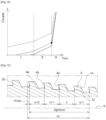
- FIG. 10 shows a screwing curve for a tube according to the state of the art including an accumulation of unabsorbed pitch error.
- One method used to ensure that connections are assembled correctly is to monitor the torque applied by a collet in relation to the number of turns.
- tightening pliers we mean a large capacity self-locking wrench used to grip the male and female components of the connection and apply a tightening/loosening torque.
- a graph can be drawn showing the torque on the vertical axis and the number of revolutions on the horizontal axis as shown in the Figure 10 ,
- the first part “I” corresponds to the tightening step where there is contact between the threads, more particularly at least contact between respective engagement flanks of a male (20) and female (21) threaded end. At this point there is little resistance for the first few turns until the respective threads begin to interfere radially.
- the second part “II” corresponds to the contact between the male and female sealing surfaces and which results in a first strong increase in the curve.
- the last part “III” corresponds to the meeting of the abutment surfaces of the male and female tubular threaded elements, which generates a sudden increase in torque over small amplitudes of relative rotation of the male and female components relative to each other. the other.
- FIG. 11 shows a screwing curve in broken lines for the assembly of a joint according to the invention, comprising an accumulation of absorbed pitch error.
- the thread axial clearance is large enough to absorb any accumulation of pitch error. There is therefore an absence of offset and consequently the curve is well within the acceptable window represented by the two solid line screwing curves.
- FIG. 12 shows in superposition a first male threaded end (20) and a second male threaded end (40), each comprising a male threaded portion (4a) and (4b).
- Each male thread tooth (6) comprises a male carrying flank (12) and engagement (14).
- the portion (4a) of the first male threaded end (20) shown in solid line does not include any pitch error, corresponding to the value on the plan or the theoretical value of the minimum value of the distance of the male pitch tolerance in mm Dpinmin.
- Each of the first (20) and second (40) male threaded ends includes a plurality of thread "steps" corresponding to an increasing or decreasing position level “n" shown on the Figure 12 by “n-1”, “n”, “n+1” etc...
- pitch we mean the distance between two successive supporting flanks, male or female, as defined by ISO 5408.
- the steps are defined by the successive male supporting sides.
- the theoretical value Dpinmin corresponds to the plane value of the total steps considered.
- Vr the theoretical value of the tolerance of the step separation ITmin.
Landscapes
- Engineering & Computer Science (AREA)
- General Engineering & Computer Science (AREA)
- Mechanical Engineering (AREA)
- Mining & Mineral Resources (AREA)
- Geology (AREA)
- Life Sciences & Earth Sciences (AREA)
- Geochemistry & Mineralogy (AREA)
- Fluid Mechanics (AREA)
- Physics & Mathematics (AREA)
- General Life Sciences & Earth Sciences (AREA)
- Environmental & Geological Engineering (AREA)
- Non-Disconnectible Joints And Screw-Threaded Joints (AREA)
- Earth Drilling (AREA)
- Yarns And Mechanical Finishing Of Yarns Or Ropes (AREA)
- Ropes Or Cables (AREA)
- Electrical Discharge Machining, Electrochemical Machining, And Combined Machining (AREA)
- Gasket Seals (AREA)
Claims (7)
- Rohrförmige Gewindeverbindung (1) für die Bohrung und den Betrieb von Kohlenwasserstoffbohrlöchern, den Transport von Öl und Gas, den Transport oder die Lagerung von Wasserstoff, Kohlenstoffabscheidung oder Geothermie, umfassend ein männliches rohrförmiges Element (2) und ein weibliches rohrförmiges Element (3), wobei das männliche (2) und das weibliche Element (3) einen männlichen Gewindeabschnitt (4) bzw. einen weiblichen Gewindeabschnitt (5) umfassen, wobei der eine oder der andere des männlichen (4) oder weiblichen Gewindeabschnitts (5) optional eine feste korrosionshemmende und/oder schmierende Beschichtung (10) umfasst, wobei der männliche Gewindeabschnitt (4) und der weibliche Gewindeabschnitt (5) mindestens einen männlichen (6) bzw. einen weiblichen Gewindezahn (5) und ein axiales Gewindespiel TAG (8) umfassen, das im montierten Zustand einen Abstand zwischen einer Eingriffsflanke (14) des männlichen Gewindezahns und einer Tragflanke (15) des weiblichen (7) Gewindezahn gewährleistet, dadurch gekennzeichnet, dass das axiale Gewindespiel TAG größer als oder so groß wie ein Mindestspiel TAGmin ist, so dass:
 mit:
mit: wobei:TAGmin Mindestwert des axialen Gewindespiels in mm ITmin Mindesttoleranzwert der Steigungsabweichung in mmLFpinmin Mindestwert der axialen Länge des männlichen Gewindes in mmLFboxmin Mindestwert der axialen Länge des weiblichen Gewindes in mmDpinmin Mindestwert des Abstands der männlichen Steigungstoleranz in mmDboxmin Mindestwert des Abstands der weiblichen Steigungstoleranz in mmEpcoat Wert der Dicke einer korrosionshemmenden und/oder schmierenden Beschichtung in mm Epcoat max Maximalwert der Dicke einer korrosionshemmenden und/oder schmierenden Beschichtung.
 - Rohrförmige Gewindeverbindung (1) nach Anspruch 1, dadurch gekennzeichnet, dass der Toleranzwert der Steigungsabweichung zwischen 0,040 und 0,080 mm, vorzugsweise zwischen 0,048 und 0,072 mm, beträgt.
- Rohrförmige Gewindeverbindung (1) nach einem der vorangehenden Ansprüche, dadurch gekennzeichnet, dass das axiale Gewindespiel TAG kleiner als oder so groß wie ein Maximalspiel TAGmax ist, so dass:
 mit:
mit: a = 0,00053b = 0,14wobei:
PinLipSurface Wert der Querschnittsfläche der männlichen Lippe zwischen der Dichtfläche und der Anschlagsfläche in mm2a Wert der Steigung der Korrelationb Wert der Ordinate am Ursprung. - Rohrförmige Gewindeverbindung (1) nach Anspruch 3, dadurch gekennzeichnet, dass das axiale Gewindespiel TAG (8) zwischen zwei Werten, TAGmin und TAGmax, liegt, so dass: TAGmin < TAGmax.
- Rohrförmige Gewindeverbindung (1) nach einem der vorangehenden Ansprüche, dadurch gekennzeichnet, dass mindestens einer des männlichen Gewindeabschnitts (4) und des weiblichen Gewindeabschnitts (5) eine korrosionshemmende und/oder schmierende Beschichtung umfasst und dass der Wert der Dicke der korrosionshemmenden und/oder schmierenden Beschichtung (10) Epcoat größer als Null ist.
- Rohrförmige Gewindeverbindung (1) nach Anspruch 5, dadurch gekennzeichnet, dass die korrosionshemmende und/oder schmierende Beschichtung eine Dicke mit einem Maximalwert Epcoat max von 0,0075 mm aufweist.
- Rohrförmige Gewindeverbindung (1) nach einem der vorangehenden Ansprüche, dadurch gekennzeichnet, dass die korrosionshemmende und/oder schmierende Beschichtung (10) eine Zink und Nickel umfassende Schicht umfasst.
Applications Claiming Priority (2)
| Application Number | Priority Date | Filing Date | Title |
|---|---|---|---|
| FR2103327A FR3121492B1 (fr) | 2021-03-31 | 2021-03-31 | Dimensionnement d’un jeu axial de filetage |
| PCT/FR2022/050508 WO2022207995A1 (fr) | 2021-03-31 | 2022-03-21 | Dimensionnement d'un jeu axial de filetage |
Publications (3)
| Publication Number | Publication Date |
|---|---|
| EP4314475A1 EP4314475A1 (de) | 2024-02-07 |
| EP4314475C0 EP4314475C0 (de) | 2024-06-26 |
| EP4314475B1 true EP4314475B1 (de) | 2024-06-26 |
Family
ID=76375192
Family Applications (1)
| Application Number | Title | Priority Date | Filing Date |
|---|---|---|---|
| EP22715127.1A Active EP4314475B1 (de) | 2021-03-31 | 2022-03-21 | Grössenbestimmung eines axialen gewindespiels |
Country Status (14)
| Country | Link |
|---|---|
| US (1) | US12286841B2 (de) |
| EP (1) | EP4314475B1 (de) |
| JP (1) | JP7514404B2 (de) |
| CN (1) | CN117062964A (de) |
| AR (1) | AR125618A1 (de) |
| AU (1) | AU2022251025B2 (de) |
| BR (1) | BR112023017681A2 (de) |
| CA (1) | CA3214589A1 (de) |
| FR (1) | FR3121492B1 (de) |
| MX (1) | MX2023011652A (de) |
| PL (1) | PL4314475T3 (de) |
| SA (1) | SA523450768B1 (de) |
| UA (1) | UA129641C2 (de) |
| WO (1) | WO2022207995A1 (de) |
Families Citing this family (2)
| Publication number | Priority date | Publication date | Assignee | Title |
|---|---|---|---|---|
| EP4215716B1 (de) | 2022-01-19 | 2024-07-31 | Tenaris Connections B.V. | Rohrschraubverbindung |
| FR3141715B1 (fr) * | 2022-11-07 | 2024-09-27 | Vallourec Oil & Gas France | Connexion tubulaire filetée |
Family Cites Families (20)
| Publication number | Priority date | Publication date | Assignee | Title |
|---|---|---|---|---|
| GB8323348D0 (en) * | 1983-08-31 | 1983-10-05 | Hunting Oilfield Services Ltd | Pipe connectors |
| CA1322773C (en) * | 1989-07-28 | 1993-10-05 | Erich F. Klementich | Threaded tubular connection |
| CA2132767C (en) * | 1994-09-23 | 1998-06-02 | Miyuki Yamamoto | Threaded joint for oil well pipes |
| EP0703396B1 (de) * | 1994-09-23 | 2000-04-05 | Sumitomo Metal Industries, Ltd. | Schraubverbindung für Ölförderrohre |
| CA2163282C (en) * | 1994-11-22 | 2002-08-13 | Miyuki Yamamoto | Threaded joint for oil well pipes |
| JP3700108B2 (ja) * | 1998-04-13 | 2005-09-28 | 株式会社メタルワン | 油井管用ネジ継手 |
| JP3714199B2 (ja) * | 2000-06-07 | 2005-11-09 | 住友金属工業株式会社 | テーパねじ継手 |
| WO2001094831A1 (en) * | 2000-06-07 | 2001-12-13 | Sumitomo Metal Industries, Ltd. | Taper threaded joint |
| FR2833335B1 (fr) * | 2001-12-07 | 2007-05-18 | Vallourec Mannesmann Oil & Gas | Joint filete tubulaire superieur contenant au moins un element filete avec levre d'extremite |
| ITRM20020274A1 (it) * | 2002-05-16 | 2003-11-17 | Tenaris Connections Bv | Giunzione filettata per tubi. |
| EP2002165B1 (de) | 2006-03-31 | 2017-09-06 | Nippon Steel & Sumitomo Metal Corporation | Rohrförmige gewindeverbindung |
| FR2939861B1 (fr) * | 2008-12-16 | 2010-12-24 | Vallourec Mannesmann Oil & Gas France | Joint tubulaire a filetage autobloquant utilise dans l'industrie du petrole |
| FR2952993B1 (fr) * | 2009-11-20 | 2011-12-16 | Vallourec Mannesmann Oil & Gas | Joint filete |
| FR2953272B1 (fr) | 2009-11-30 | 2011-12-16 | Vallourec Mannesmann Oil & Gas | Joint filete |
| JP4930647B1 (ja) * | 2010-06-30 | 2012-05-16 | Jfeスチール株式会社 | 管用ねじ継手 |
| JP2014013052A (ja) * | 2012-07-04 | 2014-01-23 | Jfe Steel Corp | 管のねじ継手 |
| FR3030668B1 (fr) * | 2014-12-19 | 2016-12-16 | Vallourec Oil & Gas France | Joint filete |
| MX2018011701A (es) * | 2016-06-08 | 2019-02-18 | Nippon Steel & Sumitomo Metal Corp | Conexion roscada para tubo de acero. |
| FR3098878B1 (fr) * | 2019-07-19 | 2021-07-30 | Vallourec Oil & Gas France | Joint fileté pour colonne de cuvelage de puits de pétrole |
| FR3098879B1 (fr) * | 2019-07-19 | 2021-07-30 | Vallourec Oil & Gas France | Joint fileté à profil hélicoïdal dissymétrique |
-
2021
- 2021-03-31 FR FR2103327A patent/FR3121492B1/fr active Active
-
2022
- 2022-03-21 EP EP22715127.1A patent/EP4314475B1/de active Active
- 2022-03-21 AU AU2022251025A patent/AU2022251025B2/en active Active
- 2022-03-21 BR BR112023017681A patent/BR112023017681A2/pt active Search and Examination
- 2022-03-21 CA CA3214589A patent/CA3214589A1/fr active Pending
- 2022-03-21 MX MX2023011652A patent/MX2023011652A/es unknown
- 2022-03-21 US US18/552,288 patent/US12286841B2/en active Active
- 2022-03-21 PL PL22715127.1T patent/PL4314475T3/pl unknown
- 2022-03-21 CN CN202280021500.6A patent/CN117062964A/zh active Pending
- 2022-03-21 UA UAA202304324A patent/UA129641C2/uk unknown
- 2022-03-21 JP JP2023558284A patent/JP7514404B2/ja active Active
- 2022-03-21 WO PCT/FR2022/050508 patent/WO2022207995A1/fr not_active Ceased
- 2022-03-30 AR ARP220100779A patent/AR125618A1/es active IP Right Grant
-
2023
- 2023-09-30 SA SA523450768A patent/SA523450768B1/ar unknown
Also Published As
| Publication number | Publication date |
|---|---|
| EP4314475C0 (de) | 2024-06-26 |
| AR125618A1 (es) | 2023-08-02 |
| AU2022251025B2 (en) | 2024-10-17 |
| CN117062964A (zh) | 2023-11-14 |
| EP4314475A1 (de) | 2024-02-07 |
| UA129641C2 (uk) | 2025-06-18 |
| MX2023011652A (es) | 2023-11-24 |
| US20240159113A1 (en) | 2024-05-16 |
| PL4314475T3 (pl) | 2024-09-02 |
| WO2022207995A1 (fr) | 2022-10-06 |
| SA523450768B1 (ar) | 2025-05-18 |
| JP2024510772A (ja) | 2024-03-11 |
| FR3121492A1 (fr) | 2022-10-07 |
| CA3214589A1 (fr) | 2022-10-06 |
| AU2022251025A1 (en) | 2023-09-21 |
| BR112023017681A2 (pt) | 2023-10-10 |
| US12286841B2 (en) | 2025-04-29 |
| JP7514404B2 (ja) | 2024-07-10 |
| FR3121492B1 (fr) | 2023-02-24 |
Similar Documents
| Publication | Publication Date | Title |
|---|---|---|
| EP3555412B1 (de) | Gewindeverbindung für rohrförmige komponente | |
| EP4314475B1 (de) | Grössenbestimmung eines axialen gewindespiels | |
| EP1295007B1 (de) | Gewindeverbindiung mit verstärktem anschlag | |
| FR2952993A1 (fr) | Joint filete | |
| FR2923283A1 (fr) | Joint filete comprenant au moins un element filete avec levre d'extremite pour tube metallique. | |
| FR2820806A1 (fr) | Joint filete tubulaire avec face de filet bombee convexe | |
| FR3030668A1 (fr) | Joint filete | |
| FR2969738A1 (fr) | Joint filete pour le forage et l'exploitation des puits d'hydrocarbures | |
| EP3994382A1 (de) | Schraubverbindung mit durch generative fertigung hergestellter schulter | |
| FR3027338A1 (fr) | Connexion polyvalente etanche a double butee | |
| EP4616042B1 (de) | Rohrgewindeanschluss | |
| FR2961576A1 (fr) | Joint filete et procede de realisation | |
| OA21327A (en) | Dimensioning of a threaded axial gap. | |
| EP4499974B1 (de) | Rohrförmige schraubverbindung | |
| FR3137735A1 (fr) | Ensemble tubulaire amélioré destiné à être raccordé à un deuxième tube | |
| EA046028B1 (ru) | Определение размеров резьбового осевого промежутка | |
| WO2021123571A1 (fr) | Connexion à capteur intégré | |
| WO2022184993A1 (fr) | Elément tubulaire fileté à segment | |
| FR2818728A1 (fr) | Joint filete tubulaire avec butee renforcee | |
| EP4399385A1 (de) | Festes schmiermittel für zn-ni-beschichtung auf einem gewinderohrelement | |
| OA19096A (fr) | Joint fileté pour composant tubulaire. |
Legal Events
| Date | Code | Title | Description |
|---|---|---|---|
| STAA | Information on the status of an ep patent application or granted ep patent |
Free format text: STATUS: UNKNOWN |
|
| STAA | Information on the status of an ep patent application or granted ep patent |
Free format text: STATUS: THE INTERNATIONAL PUBLICATION HAS BEEN MADE |
|
| PUAI | Public reference made under article 153(3) epc to a published international application that has entered the european phase |
Free format text: ORIGINAL CODE: 0009012 |
|
| STAA | Information on the status of an ep patent application or granted ep patent |
Free format text: STATUS: REQUEST FOR EXAMINATION WAS MADE |
|
| 17P | Request for examination filed |
Effective date: 20230904 |
|
| AK | Designated contracting states |
Kind code of ref document: A1 Designated state(s): AL AT BE BG CH CY CZ DE DK EE ES FI FR GB GR HR HU IE IS IT LI LT LU LV MC MK MT NL NO PL PT RO RS SE SI SK SM TR |
|
| GRAP | Despatch of communication of intention to grant a patent |
Free format text: ORIGINAL CODE: EPIDOSNIGR1 |
|
| STAA | Information on the status of an ep patent application or granted ep patent |
Free format text: STATUS: GRANT OF PATENT IS INTENDED |
|
| RIC1 | Information provided on ipc code assigned before grant |
Ipc: F16L 15/00 20060101ALI20240208BHEP Ipc: F16L 58/08 20060101ALI20240208BHEP Ipc: F16L 15/08 20060101ALI20240208BHEP Ipc: F16L 15/06 20060101ALI20240208BHEP Ipc: E21B 17/042 20060101AFI20240208BHEP |
|
| DAV | Request for validation of the european patent (deleted) | ||
| DAX | Request for extension of the european patent (deleted) | ||
| INTG | Intention to grant announced |
Effective date: 20240307 |
|
| GRAS | Grant fee paid |
Free format text: ORIGINAL CODE: EPIDOSNIGR3 |
|
| GRAA | (expected) grant |
Free format text: ORIGINAL CODE: 0009210 |
|
| STAA | Information on the status of an ep patent application or granted ep patent |
Free format text: STATUS: THE PATENT HAS BEEN GRANTED |
|
| AK | Designated contracting states |
Kind code of ref document: B1 Designated state(s): AL AT BE BG CH CY CZ DE DK EE ES FI FR GB GR HR HU IE IS IT LI LT LU LV MC MK MT NL NO PL PT RO RS SE SI SK SM TR |
|
| REG | Reference to a national code |
Ref country code: GB Ref legal event code: FG4D Free format text: NOT ENGLISH |
|
| REG | Reference to a national code |
Ref country code: CH Ref legal event code: EP |
|
| REG | Reference to a national code |
Ref country code: DE Ref legal event code: R096 Ref document number: 602022004188 Country of ref document: DE |
|
| U01 | Request for unitary effect filed |
Effective date: 20240705 |
|
| U07 | Unitary effect registered |
Designated state(s): AT BE BG DE DK EE FI FR IT LT LU LV MT NL PT RO SE SI Effective date: 20240902 |
|
| PG25 | Lapsed in a contracting state [announced via postgrant information from national office to epo] |
Ref country code: HR Free format text: LAPSE BECAUSE OF FAILURE TO SUBMIT A TRANSLATION OF THE DESCRIPTION OR TO PAY THE FEE WITHIN THE PRESCRIBED TIME-LIMIT Effective date: 20240626 |
|
| PG25 | Lapsed in a contracting state [announced via postgrant information from national office to epo] |
Ref country code: GR Free format text: LAPSE BECAUSE OF FAILURE TO SUBMIT A TRANSLATION OF THE DESCRIPTION OR TO PAY THE FEE WITHIN THE PRESCRIBED TIME-LIMIT Effective date: 20240927 |
|
| PG25 | Lapsed in a contracting state [announced via postgrant information from national office to epo] |
Ref country code: HR Free format text: LAPSE BECAUSE OF FAILURE TO SUBMIT A TRANSLATION OF THE DESCRIPTION OR TO PAY THE FEE WITHIN THE PRESCRIBED TIME-LIMIT Effective date: 20240626 Ref country code: GR Free format text: LAPSE BECAUSE OF FAILURE TO SUBMIT A TRANSLATION OF THE DESCRIPTION OR TO PAY THE FEE WITHIN THE PRESCRIBED TIME-LIMIT Effective date: 20240927 Ref country code: RS Free format text: LAPSE BECAUSE OF FAILURE TO SUBMIT A TRANSLATION OF THE DESCRIPTION OR TO PAY THE FEE WITHIN THE PRESCRIBED TIME-LIMIT Effective date: 20240926 |
|
| PG25 | Lapsed in a contracting state [announced via postgrant information from national office to epo] |
Ref country code: IS Free format text: LAPSE BECAUSE OF FAILURE TO SUBMIT A TRANSLATION OF THE DESCRIPTION OR TO PAY THE FEE WITHIN THE PRESCRIBED TIME-LIMIT Effective date: 20241026 |
|
| PG25 | Lapsed in a contracting state [announced via postgrant information from national office to epo] |
Ref country code: SK Free format text: LAPSE BECAUSE OF FAILURE TO SUBMIT A TRANSLATION OF THE DESCRIPTION OR TO PAY THE FEE WITHIN THE PRESCRIBED TIME-LIMIT Effective date: 20240626 |
|
| PG25 | Lapsed in a contracting state [announced via postgrant information from national office to epo] |
Ref country code: ES Free format text: LAPSE BECAUSE OF FAILURE TO SUBMIT A TRANSLATION OF THE DESCRIPTION OR TO PAY THE FEE WITHIN THE PRESCRIBED TIME-LIMIT Effective date: 20240626 Ref country code: SM Free format text: LAPSE BECAUSE OF FAILURE TO SUBMIT A TRANSLATION OF THE DESCRIPTION OR TO PAY THE FEE WITHIN THE PRESCRIBED TIME-LIMIT Effective date: 20240626 |
|
| PG25 | Lapsed in a contracting state [announced via postgrant information from national office to epo] |
Ref country code: SM Free format text: LAPSE BECAUSE OF FAILURE TO SUBMIT A TRANSLATION OF THE DESCRIPTION OR TO PAY THE FEE WITHIN THE PRESCRIBED TIME-LIMIT Effective date: 20240626 Ref country code: SK Free format text: LAPSE BECAUSE OF FAILURE TO SUBMIT A TRANSLATION OF THE DESCRIPTION OR TO PAY THE FEE WITHIN THE PRESCRIBED TIME-LIMIT Effective date: 20240626 Ref country code: IS Free format text: LAPSE BECAUSE OF FAILURE TO SUBMIT A TRANSLATION OF THE DESCRIPTION OR TO PAY THE FEE WITHIN THE PRESCRIBED TIME-LIMIT Effective date: 20241026 Ref country code: ES Free format text: LAPSE BECAUSE OF FAILURE TO SUBMIT A TRANSLATION OF THE DESCRIPTION OR TO PAY THE FEE WITHIN THE PRESCRIBED TIME-LIMIT Effective date: 20240626 |
|
| U20 | Renewal fee for the european patent with unitary effect paid |
Year of fee payment: 4 Effective date: 20250210 |
|
| PLBE | No opposition filed within time limit |
Free format text: ORIGINAL CODE: 0009261 |
|
| STAA | Information on the status of an ep patent application or granted ep patent |
Free format text: STATUS: NO OPPOSITION FILED WITHIN TIME LIMIT |
|
| 26N | No opposition filed |
Effective date: 20250327 |
|
| PG25 | Lapsed in a contracting state [announced via postgrant information from national office to epo] |
Ref country code: MC Free format text: LAPSE BECAUSE OF FAILURE TO SUBMIT A TRANSLATION OF THE DESCRIPTION OR TO PAY THE FEE WITHIN THE PRESCRIBED TIME-LIMIT Effective date: 20240626 |
|
| REG | Reference to a national code |
Ref country code: CH Ref legal event code: H13 Free format text: ST27 STATUS EVENT CODE: U-0-0-H10-H13 (AS PROVIDED BY THE NATIONAL OFFICE) Effective date: 20251023 |
|
| PG25 | Lapsed in a contracting state [announced via postgrant information from national office to epo] |
Ref country code: CH Free format text: LAPSE BECAUSE OF NON-PAYMENT OF DUE FEES Effective date: 20250331 |
|
| PG25 | Lapsed in a contracting state [announced via postgrant information from national office to epo] |
Ref country code: IE Free format text: LAPSE BECAUSE OF NON-PAYMENT OF DUE FEES Effective date: 20250321 |
|
| U20 | Renewal fee for the european patent with unitary effect paid |
Year of fee payment: 5 Effective date: 20260219 |
|
| PGFP | Annual fee paid to national office [announced via postgrant information from national office to epo] |
Ref country code: GB Payment date: 20260220 Year of fee payment: 5 |
|
| PGFP | Annual fee paid to national office [announced via postgrant information from national office to epo] |
Ref country code: NO Payment date: 20260223 Year of fee payment: 5 |
|
| PGFP | Annual fee paid to national office [announced via postgrant information from national office to epo] |
Ref country code: CZ Payment date: 20260302 Year of fee payment: 5 |
|
| PGFP | Annual fee paid to national office [announced via postgrant information from national office to epo] |
Ref country code: PL Payment date: 20260219 Year of fee payment: 5 |