EP4314517B1 - Tube d'ejection integre a un tube central de ventilation - Google Patents
Tube d'ejection integre a un tube central de ventilation Download PDFInfo
- Publication number
- EP4314517B1 EP4314517B1 EP22715143.8A EP22715143A EP4314517B1 EP 4314517 B1 EP4314517 B1 EP 4314517B1 EP 22715143 A EP22715143 A EP 22715143A EP 4314517 B1 EP4314517 B1 EP 4314517B1
- Authority
- EP
- European Patent Office
- Prior art keywords
- tube
- tubular structure
- air
- upstream
- internal tubular
- Prior art date
- Legal status (The legal status is an assumption and is not a legal conclusion. Google has not performed a legal analysis and makes no representation as to the accuracy of the status listed.)
- Active
Links
Images


Classifications
-
- F—MECHANICAL ENGINEERING; LIGHTING; HEATING; WEAPONS; BLASTING
- F01—MACHINES OR ENGINES IN GENERAL; ENGINE PLANTS IN GENERAL; STEAM ENGINES
- F01D—NON-POSITIVE DISPLACEMENT MACHINES OR ENGINES, e.g. STEAM TURBINES
- F01D25/00—Component parts, details, or accessories, not provided for in, or of interest apart from, other groups
- F01D25/18—Lubricating arrangements
-
- F—MECHANICAL ENGINEERING; LIGHTING; HEATING; WEAPONS; BLASTING
- F01—MACHINES OR ENGINES IN GENERAL; ENGINE PLANTS IN GENERAL; STEAM ENGINES
- F01D—NON-POSITIVE DISPLACEMENT MACHINES OR ENGINES, e.g. STEAM TURBINES
- F01D25/00—Component parts, details, or accessories, not provided for in, or of interest apart from, other groups
- F01D25/30—Exhaust heads, chambers, or the like
-
- F—MECHANICAL ENGINEERING; LIGHTING; HEATING; WEAPONS; BLASTING
- F02—COMBUSTION ENGINES; HOT-GAS OR COMBUSTION-PRODUCT ENGINE PLANTS
- F02C—GAS-TURBINE PLANTS; AIR INTAKES FOR JET-PROPULSION PLANTS; CONTROLLING FUEL SUPPLY IN AIR-BREATHING JET-PROPULSION PLANTS
- F02C7/00—Features, components parts, details or accessories, not provided for in, or of interest apart form groups F02C1/00 - F02C6/00; Air intakes for jet-propulsion plants
- F02C7/06—Arrangements of bearings; Lubricating
-
- B—PERFORMING OPERATIONS; TRANSPORTING
- B33—ADDITIVE MANUFACTURING TECHNOLOGY
- B33Y—ADDITIVE MANUFACTURING, i.e. MANUFACTURING OF THREE-DIMENSIONAL [3D] OBJECTS BY ADDITIVE DEPOSITION, ADDITIVE AGGLOMERATION OR ADDITIVE LAYERING, e.g. BY 3D PRINTING, STEREOLITHOGRAPHY OR SELECTIVE LASER SINTERING
- B33Y10/00—Processes of additive manufacturing
-
- F—MECHANICAL ENGINEERING; LIGHTING; HEATING; WEAPONS; BLASTING
- F05—INDEXING SCHEMES RELATING TO ENGINES OR PUMPS IN VARIOUS SUBCLASSES OF CLASSES F01-F04
- F05D—INDEXING SCHEME FOR ASPECTS RELATING TO NON-POSITIVE-DISPLACEMENT MACHINES OR ENGINES, GAS-TURBINES OR JET-PROPULSION PLANTS
- F05D2230/00—Manufacture
- F05D2230/20—Manufacture essentially without removing material
- F05D2230/23—Manufacture essentially without removing material by permanently joining parts together
- F05D2230/232—Manufacture essentially without removing material by permanently joining parts together by welding
- F05D2230/234—Laser welding
-
- F—MECHANICAL ENGINEERING; LIGHTING; HEATING; WEAPONS; BLASTING
- F05—INDEXING SCHEMES RELATING TO ENGINES OR PUMPS IN VARIOUS SUBCLASSES OF CLASSES F01-F04
- F05D—INDEXING SCHEME FOR ASPECTS RELATING TO NON-POSITIVE-DISPLACEMENT MACHINES OR ENGINES, GAS-TURBINES OR JET-PROPULSION PLANTS
- F05D2230/00—Manufacture
- F05D2230/30—Manufacture with deposition of material
-
- F—MECHANICAL ENGINEERING; LIGHTING; HEATING; WEAPONS; BLASTING
- F05—INDEXING SCHEMES RELATING TO ENGINES OR PUMPS IN VARIOUS SUBCLASSES OF CLASSES F01-F04
- F05D—INDEXING SCHEME FOR ASPECTS RELATING TO NON-POSITIVE-DISPLACEMENT MACHINES OR ENGINES, GAS-TURBINES OR JET-PROPULSION PLANTS
- F05D2230/00—Manufacture
- F05D2230/30—Manufacture with deposition of material
- F05D2230/31—Layer deposition
-
- F—MECHANICAL ENGINEERING; LIGHTING; HEATING; WEAPONS; BLASTING
- F05—INDEXING SCHEMES RELATING TO ENGINES OR PUMPS IN VARIOUS SUBCLASSES OF CLASSES F01-F04
- F05D—INDEXING SCHEME FOR ASPECTS RELATING TO NON-POSITIVE-DISPLACEMENT MACHINES OR ENGINES, GAS-TURBINES OR JET-PROPULSION PLANTS
- F05D2230/00—Manufacture
- F05D2230/50—Building or constructing in particular ways
- F05D2230/53—Building or constructing in particular ways by integrally manufacturing a component, e.g. by milling from a billet or one piece construction
-
- F—MECHANICAL ENGINEERING; LIGHTING; HEATING; WEAPONS; BLASTING
- F05—INDEXING SCHEMES RELATING TO ENGINES OR PUMPS IN VARIOUS SUBCLASSES OF CLASSES F01-F04
- F05D—INDEXING SCHEME FOR ASPECTS RELATING TO NON-POSITIVE-DISPLACEMENT MACHINES OR ENGINES, GAS-TURBINES OR JET-PROPULSION PLANTS
- F05D2260/00—Function
- F05D2260/60—Fluid transfer
- F05D2260/601—Fluid transfer using an ejector or a jet pump
-
- F—MECHANICAL ENGINEERING; LIGHTING; HEATING; WEAPONS; BLASTING
- F05—INDEXING SCHEMES RELATING TO ENGINES OR PUMPS IN VARIOUS SUBCLASSES OF CLASSES F01-F04
- F05D—INDEXING SCHEME FOR ASPECTS RELATING TO NON-POSITIVE-DISPLACEMENT MACHINES OR ENGINES, GAS-TURBINES OR JET-PROPULSION PLANTS
- F05D2260/00—Function
- F05D2260/60—Fluid transfer
- F05D2260/605—Venting into the ambient atmosphere or the like
-
- F—MECHANICAL ENGINEERING; LIGHTING; HEATING; WEAPONS; BLASTING
- F05—INDEXING SCHEMES RELATING TO ENGINES OR PUMPS IN VARIOUS SUBCLASSES OF CLASSES F01-F04
- F05D—INDEXING SCHEME FOR ASPECTS RELATING TO NON-POSITIVE-DISPLACEMENT MACHINES OR ENGINES, GAS-TURBINES OR JET-PROPULSION PLANTS
- F05D2260/00—Function
- F05D2260/60—Fluid transfer
- F05D2260/609—Deoiling or demisting
Definitions
- the present invention relates to a central ventilation tube of a turbomachine.
- a turbomachine such as a turbojet, may include an exhaust system configured to extract and channel pressurizing air from the bearing housings and eject it to the atmosphere.
- the exhaust system typically includes a central vent tube, within which is positioned an inner tubular structure that forms a constriction within the central vent tube.
- the tube and the inner tubular structure are two independent parts that are in contact. Static and vibration stresses can lead to cracking of the inner tubular structure in the area of contact with the central ventilation tube, resulting in damage to the exhaust system.
- the present invention therefore provides an air exhaust system with improved integration of the inner tubular structure within the central ventilation tube as well as a method of manufacturing the system.
- the proposed exhaust system integrates the central ventilation tube and the inner tubular structure into a single part.
- Said upstream portion may comprise a free space (90) being formed between the tube (70) and the inner tubular structure (10) such that the tube and the inner tubular structure are connected only at the downstream end, the tube and the inner tubular structure preferably being connected only along a circumference of the downstream end.
- said tube and the inner tubular structure may be separated by an annular slot (100) at the upstream end such that the inner tubular structure is freely suspended at the upstream end, the annular slot preferably having a size of 1.5 mm or more.
- a wall (110) of the tube may include at least one opening (120) configured to allow removal of unmelted powder located between the tube and the interior tubular structure.
- Said tube (70) may have a cylindrical shape, with a longitudinal axis (220) and a first angle (140) between a wall of the inner tubular structure (10) and the longitudinal axis may be 50° or less.
- a wall thickness (150) of the pipe and the inner tubular structure may be between 0.8 mm and 1.2 mm.
- the extension pipe may comprise a material different from the material of the upstream part.
- the present invention also relates to a turbomachine with a device (200) for evacuating air from the bearing enclosures, the air being conducted to the outside of the turbomachine by an air evacuation system as presented above.
- the invention also relates to a method of manufacturing an upstream part of an air evacuation system as presented previously, by laser fusion on a powder bed.
- laser melting may take place from the upstream end to the downstream end.
- the invention also relates to a method of manufacturing the air evacuation system presented above, the method comprising the steps presented above and a step of assembling the extension pipe to the upstream part by a welding method.
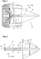
- FIG. 1 shows a turbomachine comprising a device (200) for evacuating air from the bearing enclosures.
- a turbomachine for example a turbojet, comprises an air inlet comprising a fan whose outlet air flow is divided into an air flow which enters the engine and forms a hot flow or primary flow, and into an air flow which flows around the engine and which forms a cold flow or secondary flow.
- the engine typically comprises, from upstream to downstream, in the direction of gas flow, at least one compressor, a combustion chamber, at least one turbine, and an ejection device in which the combustion gases leaving the turbine and forming the primary flow are mixed with the secondary flow.
- the turbomachine At its downstream end, the turbomachine comprises an ejection cone (190) for the primary flow, or even for the primary flow-secondary flow mixture.
- This cone has an elongated shape, the upstream end of larger diameter of which is fixed to an element of the turbomachine, such as a casing.
- a central ventilation tube (20) longitudinally passes through the ejection cone (190).
- the function of this central ventilation tube (20) is to extract and channel the air discharged from the oil by the oil separators of the turbomachine and to eject it to the atmosphere via the downstream end of the tube (20), located substantially at the downstream end of the ejection cone (190).
- air from the bearing enclosures of the turbomachine is conducted to the outside via the central ventilation tube (20).
- the central ventilation tube contains an inner tubular structure (10), which has a constriction (170), or in other words a reduced diameter section (170), in order to cause a Venturi effect for the air flowing through the inner tubular structure.
- a nozzle (300) brings purge air to this constriction (170), which creates a low pressure suction by the Venturi effect, drawing the purge air from the nozzle and then ejecting it to the outside.
- the direction of the air flow, from upstream to downstream in the turbomachine in operation is indicated by an arrow 230.
- FIG. 2 shows the central ventilation tube (20) located inside the ejection cone (190).
- This tube comprises an upstream part (40) followed, downstream, by an extension tube (160), the inlet of which is indicated by the arrow 280.
- the upstream part (40) itself comprises an upstream end (50) and a downstream end (60).
- the upstream portion comprises a tube (70), preferably cylindrical in shape, having a longitudinal axis (220).
- the inner tubular structure (10) is located inside this tube (70) and forms the narrowing (170) there.
- the extension tube (160) is bonded to the downstream end (60) of the upstream portion (40) to form an extension of the tube (70).
- the extension tube may be bonded to the upstream portion (40) by a weld (180).
- the extension tube may comprise a material different from the material of the upstream portion.
- the latter may comprise a material particularly well suited for manufacturing by laser powder bed fusion or another additive manufacturing process.
- the extension tube may comprise a material suitable for manufacturing by other methods.
- upstream part and the extension tube in one piece, for example by a laser powder bed fusion process or another additive manufacturing process.
- FIG. 3a shows a section, in a plane which contains the longitudinal axis (220) of the tube (70), of the upstream part (40) of the central ventilation tube (20) of the figure 2 .
- the end (280) of the extension tube is also seen as well as the upstream part (40), comprising the tube (70) between the upstream end (50) and the downstream end (60).
- the tube can have a diameter of 78 mm.
- the inner tubular structure (10) forms the narrowing (170) inside (80) of the tube. In other words, air entering through the upstream end (50) to exit through the downstream end must pass through a passage whose section, relative to the diameter of the tube, first contracts to expand further.
- the narrowing (170) is asymmetrical with respect to the longitudinal axis (220) of the tube, more precisely the narrowing is eccentric with respect to the longitudinal axis (220).
- the air entering through the upstream end (50) is deflected from the longitudinal axis (220) by the asymmetrical constriction.
- the asymmetrical shape has the advantage of avoiding oil retention upstream of the constriction area, which ensures a permanent flow of oil to the outside.
- FIG. 3c shows an enlargement of the downstream end (60) of the inner tubular structure and the tube.
- the inner tubular structure is integral with the tube at the downstream end (60).
- first part and the second part are made integrally and in a single piece.
- the inner tubular structure and the tube are made integrally, or else, at the downstream end, there is a continuity of material between a wall of the tube and a wall of the inner tubular structure.
- the inner tubular structure is integral with the tube over an entire circumference at the downstream end. In this way, the inner tubular structure and the tube are connected in a reliable and durable manner and the service life of the central ventilation tube is ensured.
- FIG 3b shows an enlargement of the upstream end (40) of the central ventilation tube.
- the inner tubular structure is freely suspended at this end.
- the inner tubular structure is not bonded to the tube.
- the tube and the inner tubular structure are bonded only at the downstream end so as to leave a free space (90) between a wall (110) of the tube and the inner tubular structure.
- the tube and the inner tubular structure can be bonded only along the circumference of the downstream end.
- At the upstream end there is a space of a size d between the inner tubular structure and the tube, as illustrated in Figures 3a and 3b . This space may form an annular slot (100) at the upstream end so that the inner tubular structure is freely suspended therein.
- the annular slot may have a size of 1.5 mm or more.
- the free space (90) is in communication with the outside by the space left between the inner tubular structure and the tube or by the annular slot (100).
- the upstream portion (40) is, in this way, particularly well suited to a one-piece manufacture by a laser powder bed fusion process. Following this formation of the upstream portion, the free space (90) is filled with powder which has not been fused to form the walls (110) and the like. parts of this upstream part (40). This powder can be discharged outside through the space of size d, or the annular slot (100), as illustrated in Figures 3a and 3b .
- the tube and the inner tubular structure which are integrally formed at the downstream end and free at the upstream end are thus particularly well suited to single-piece manufacturing, by laser fusion on a powder bed.
- the wall (110) of the tube may comprise one or more lateral opening(s) (120) configured to allow removal of unmelted or unfused powder.
- the thickness (150) of the wall (110) of the tube and the inner tubular structure may be 0.8 mm or 1 mm or 1.2 mm. It is also possible to have a thickness that varies between 0.8 mm and 1 mm or between 1 mm and 1.2 mm or between 0.8 mm and 1.2 mm. It is thus possible to choose one or more thicknesses for the upstream part of the central ventilation tube. A thickness between 0.8 mm and 1.2 mm is particularly well suited for manufacturing by laser powder bed fusion.
- the length (130) of the upstream part (40) of the central ventilation tube may be 600 mm or less, which is compatible with easy manufacturing on a large number of laser powder bed fusion installations.
- FIGS. 4a and 4b show a section along the same plane as the Figure 3a . These figures also show a powder (250), located between the tube and the inner tubular structure, as well as a manufacturing support (260), which is not part of the central ventilation tube.
- Reference 140 designates a first angle (140) of orientation of the wall of the inner tubular structure relative to the longitudinal axis (220).
- Reference 240 designates an angle of orientation of the wall of the inner tubular structure relative to an axis perpendicular to the longitudinal axis (220).
- the manufacturing support (260) can be flat and support the manufacturing of a flange (90) at the upstream end of the tube. During the formation of the flange, by powder fusion, the support provides support to the material forming the flange, until it stiffens. Generally, the support (260) facilitates the start of the construction of the part.
- the support (260) can be in material continuity with the part. In this case, the first grains of powder which form the flange are fused with the material of the support (260). In this case, the support must be separated from the part in the end, for example by machining.
- the first angle (140) between the wall and the longitudinal axis is 50° or less.
- the second angle between the wall and a vertical axis is 40° or more.
- a first or second wall angle within this range of values is particularly well suited for laser powder bed fusion manufacturing. Said range of values is advantageous because a wall having a first angle of 50° or less with the longitudinal axis can be manufactured without an addition of material (270) between the part and the support (260), as shown in FIG. Figure 4b .
- the material addition (270) becomes necessary for a first angle of more than 50°. It is formed on the air inlet side and stabilizes the part or wall during powder melting. The material addition is then machined to form the wall.
- This block of material forming the material addition (270) can be manufactured in material addition manufacturing, such as by powder melting.
- the material addition can have parameters different from those of the part, such as for example a lower density. The lower density of the material addition compared to the part facilitates machining, for example to form the wall.
- the entire part can be manufactured in one piece, including the additions of material.
- the manufacturing support (260) allowing the entire part to be supported from the start of manufacturing and the addition(s) of material (270) which may be necessary for the manufacture of certain parts of the part because the manufacturing angle is too small.
- the manufacturing method comprises manufacturing the upstream part (40) in a single piece by laser powder bed fusion.
- this additive manufacturing by laser fusion begins with the formation of the upstream end and ends with the manufacturing of the downstream end.
- the flange (90) can thus be easily manufactured at the beginning of the process, by resting on the support (260).
- the manufacturing can take place from the downstream end (60) towards the upstream end (50).
- powder (250) remains in the free space (90) and must be removed. This is powder not used for the formation of the walls. This powder can be removed (210) through the space provided between the tube and the inner tubular structure, located at the upstream end. The unmelted powder can be removed through the annular slot (100). Advantageously, powder can also exit through the opening(s) (120) in the wall (110) of the tube.
- the tube and the inner tubular structure are thus manufactured in one piece by an additive process, preferably laser powder bed fusion as described above.
- the upstream part by laser powder bed fusion can be made of "Inconel 718" (registered trademark).
- Iconel 718 can comprise, in mass percentage, 50-55% Ni, 17-21% Cr, 15-21% Fe, 4.75-5.5% Nb, 2.8-3.3% Mo, 0.65-1.15% Ti and 0.2-0.8% Al. This material is particularly well suited for manufacturing by laser powder bed fusion.
- the extension tube may also be made of Inconel 718.
- the extension tube may be made of "Inconel 625" (registered trademark).
- Iconel 625 may comprise, in mass percentage, Ni 58% or more, Cr 20-23%, Fe 5% or less, Mo 8-10%, Nb 3.15-4.15, Co 1% or less, Mn 0.5% or less, Al 0.4% or less, Ti 0.4% or less, Si 0.5% or less, C 0.1% or less, S 0.015% or less and P 0.015% or less.
Landscapes
- Engineering & Computer Science (AREA)
- Mechanical Engineering (AREA)
- General Engineering & Computer Science (AREA)
- Chemical & Material Sciences (AREA)
- Combustion & Propulsion (AREA)
- Powder Metallurgy (AREA)
- Laser Beam Processing (AREA)
- Jet Pumps And Other Pumps (AREA)
Description
- La présente invention se rapporte à un tube central de ventilation d'une turbomachine.
- Une turbomachine, par exemple un turboréacteur, peut comprendre un système d'évacuation configuré pour extraire et canaliser de l'air de pressurisation des enceintes de palier et l'éjecter à l'atmosphère. Le système d'évacuation comprend habituellement un tube central de ventilation, dans lequel est positionnée une structure tubulaire intérieure qui forme un rétrécissement à l'intérieur du tube central de ventilation.
- Des vibrations et des différences d'échauffement peuvent causer des fissures entre le tube central et la structure tubulaire intérieure, résultant en un endommagement du système d'évacuation. Le tube et la structure tubulaire intérieure sont deux pièces indépendantes qui sont en contact. Des sollicitations statiques et vibratoires peuvent conduire à la fissuration de la structure tubulaire intérieure dans la zone de contact avec le tube central de ventilation, résultant en un endommagement du système d'évacuation.
- Les documents
FR 2995634 A1 US 2011/146224 A1 présentent des systèmes de l'art antérieur. - La présente invention propose par conséquent un système d'évacuation d'air avec une intégration améliorée de la structure tubulaire intérieure au sein du tube central de ventilation ainsi qu'une méthode de fabrication du système. Le système d'évacuation proposé intègre le tube central de ventilation et la structure tubulaire intérieure dans une pièce unique.
- C'est par conséquent un but de la présente invention d'offrir une partie amont (40) d'un système d'évacuation d'air (20) pour une turbomachine (30), comprenant :
- un tube (70) avec une extrémité amont (50) et une extrémité aval (60),
- une structure tubulaire intérieure (10) située à l'intérieur (80) dudit tube (70) et configurée pour y former un rétrécissement de sa section (170),
la structure tubulaire intérieure (10) étant venue de matière avec le tube (10) à l'extrémité aval (60) du tube et librement suspendue à l'extrémité amont (50) du tube. - Ladite partie amont peut comprendre un espace libre (90) étant formé entre le tube (70) et la structure tubulaire intérieure (10) de façon à ce que le tube et la structure tubulaire intérieure sont liés uniquement à l'extrémité aval, le tube et la structure tubulaire intérieure étant de préférence liés uniquement le long d'une circonférence de l'extrémité aval.
- Selon une variante, ledit tube et la structure tubulaire intérieure peuvent être séparés par une fente annulaire (100) à l'extrémité amont de façon à ce que la structure tubulaire intérieure soit librement suspendue à l'extrémité amont, la fente annulaire ayant de préférence une taille de 1.5 mm ou plus.
- Une paroi (110) du tube peut comprendre au moins une ouverture (120) configurée pour permettre d'enlever une poudre non fondue, située entre le tube et la structure tubulaire intérieure.
- Ledit tube (70) peut avoir une forme cylindrique, avec un axe longitudinal (220) et un premier angle (140) entre une paroi de la structure tubulaire intérieure (10) et l'axe longitudinal peut être de 50° ou moins.
- Une épaisseur (150) de paroi (110) du tuyau et de la structure tubulaire intérieure peut être comprise entre 0.8 mm et 1.2 mm.
- L'invention concerne également un système d'évacuation de l'air comprenant
- ladite partie amont et
- un tube d'extension (160),
- le tube d'extension étant lié à l'extrémité aval du tube (70) de façon à en former une prolongation et à former une partie aval du système d'évacuation de l'air,
- le tube d'extension étant lié à au tube (70) de préférence par une soudure (180).
- Dans ledit système d'évacuation de l'air le tuyau d'extension peut comprendre un matériau différent du matériau de la partie amont.
- La présente invention concerne aussi une turbomachine avec un dispositif d'évacuation (200) de l'air des enceintes de paliers,
l'air étant conduit vers l'extérieur de la turbomachine par un système d'évacuation de l'air tel que présenté ci-dessus. - L'invention concerne également un procédé de fabrication d'une partie amont d'un système d'évacuation d'air tel que présenté auparavant, par fusion laser sur lit de poudre.
- Pendant ledit procédé de fabrication, la fusion laser peut avoir lieu depuis l'extrémité amont vers l'extrémité aval.
- L'invention concerne aussi un procédé de fabrication du système d'évacuation de l'air présenté auparavant, le procédé comprenant les étapes présentées ci-dessus et une étape d'assemblage du tuyau d'extension à la partie amont par un procédé de soudage.
- La présente invention sera mieux comprise sur la base de la description qui va suivre et des dessins en annexe sur lesquels :
- la
figure 1 montre une turbomachine comprenant un dispositif d'évacuation (200) de l'air des enceintes de paliers, - la
figure 2 montre un tube central de ventilation situé à l'intérieur du cône d'éjection, - les
figures 3a, 3b et 3c montrent une coupe de la partie amont du tube central de ventilation, - les
figures 4a et 4b montrent une coupe de la partie amont du tube central de ventilation avec un support de fabrication. - La
figure 1 montre une turbomachine comprenant un dispositif d'évacuation (200) de l'air des enceintes de paliers. - Une turbomachine, par exemple un turboréacteur à double flux, comprend une entrée d'air comportant une soufflante dont le flux d'air en sortie se divise en un flux d'air qui pénètre dans le moteur et forme un flux chaud ou flux primaire, et en un flux d'air qui s'écoule autour du moteur et qui forme un flux froid ou flux secondaire.
- Le moteur comprend typiquement, d'amont en aval, dans le sens d'écoulement des gaz, au moins un compresseur, une chambre de combustion, au moins une turbine, et un dispositif d'éjection dans lequel les gaz de combustion sortant de la turbine et formant le flux primaire sont mélangés au flux secondaire.
- A son extrémité aval, la turbomachine comprend un cône d'éjection (190) du flux primaire, voire du mélange flux primaire-flux secondaire. Ce cône a une forme allongée dont l'extrémité amont de plus grand diamètre est fixée à un élément de la turbomachine, tel qu'un carter.
- Un tube central de ventilation (20) traverse longitudinalement le cône d'éjection (190). Ce tube central de ventilation (20) a pour fonction d'extraire et de canaliser l'air déchargé d'huile par les déshuileurs de la turbomachine et de l'éjecter vers l'atmosphère par l'extrémité aval du tube (20), située sensiblement au niveau de l'extrémité aval du cône d'éjection (190). Ainsi, de l'air des enceintes de paliers de la turbomachine est conduit vers l'extérieur par le tube central de ventilation (20).
- Le tube central de ventilation contient une structure tubulaire intérieure (10), laquelle comporte un rétrécissement (170), ou autrement dit une section à diamètre réduit (170), afin de provoquer un effet Venturi pour l'air circulant dans la structure tubulaire intérieure. Une buse (300) amène de l'air de purge vers ce rétrécissement (170), qui crée une aspiration à basse pression par l'effet Venturi, tirant l'air de purge de la buse pour ensuite l'éjecter vers l'extérieur. Sur cette figure, comme en
figure 2 , la direction du flux d''air, d'amont en aval dans la turbomachine en fonctionnement, est indiquée par une flèche 230. - La
figure 2 montre le tube central de ventilation (20) situé à l'intérieur du cône d'éjection (190). Ce tube comprend une partie amont (40) suivie, en aval, d'un tube d'extension (160), dont l'entrée est indiquée par la flèche 280. La partie amont (40) comprend elle-même une extrémité amont (50) et une extrémité aval (60). - La partie amont comprend un tube (70), de préférence de forme cylindrique, ayant un axe longitudinal (220). La structure tubulaire intérieure (10) est située à l'intérieur de ce tube (70) et y forme le rétrécissement (170).
- Le tube d'extension (160) est lié à l'extrémité aval (60) de la partie amont (40) de façon à former une prolongation du tube (70). Le tube d'extension peut être lié à la partie amont (40) par une soudure (180). Dans ce cas, le tube d'extension peut comprendre un matériau différent du matériau de la partie amont. Par exemple, cette dernière peut comprendre un matériau particulièrement bien adapté à une fabrication par fusion laser sur lit de poudre ou à un autre procédé de fabrication additive. Le tube d'extension peut comprendre un matériau adapté à une fabrication par d'autres méthodes.
- Il est également envisageable de fabriquer la partie amont et le tube d'extension d'un seul tenant, par exemple par un procédé de fusion laser sur lit de poudre ou un autre procédé de fabrication additive.
- La
figure 3a montre une coupe, dans un plan qui contient l'axe longitudinal (220) du tube (70), de la partie amont (40) du tube central de ventilation (20) de lafigure 2 . Sur cette figure, on voit également l'extrémité (280) du tube d'extension ainsi que la partie amont (40), comprenant le tube (70) entre l'extrémité amont (50) et l'extrémité aval (60). Le tube peut avoir un diamètre de 78 mm. La structure tubulaire intérieure (10) forme le rétrécissement (170) à l'intérieur (80) du tube. Autrement dit, de l'air qui entre par l'extrémité amont (50) pour sortir par l'extrémité aval doit traverser un passage dont la section, par rapport au diamètre du tube, se contracte d'abord pour s'élargir plus loin. De façon avantageuse, comme illustré enfigure 3a , le rétrécissement (170) est asymétrique par rapport à l'axe longitudinal (220) du tube, plus précisément le rétrécissement est excentré par rapport à l'axe longitudinal (220). Autrement dit, l'air qui entre par l'extrémité amont (50) est dévié de l'axe longitudinal (220) par le rétrécissement asymétrique. La forme asymétrique a l'avantage d'éviter une rétention d'huile en amont de la zone du rétrécissement, ce qui assure en permanence un écoulement de l'huile vers l'extérieur. - La
figure 3c montre un agrandissement de l'extrémité aval (60) de la structure tubulaire intérieure et du tube. La structure tubulaire intérieure est venue de matière avec le tube à l'extrémité aval (60). De façon générale, par une première pièce « venue » de matière avec une deuxième pièce on comprend que la première pièce et la deuxième pièce sont réalisées de manière intégrale et en une seule pièce. Autrement dit, la structure tubulaire intérieure et le tube sont réalisés de manière intégrale, ou bien encore, à l'extrémité aval, il existe une continuité de matière entre une paroi du tube et une paroi de la structure tubulaire intérieure. De préférence, la structure tubulaire intérieure est venue de matière avec le tube sur toute une circonférence à l'extrémité aval. De cette façon, la structure tubulaire intérieure et le tube sont liés de façon fiable et durable et la durée de vie du tube central de ventilation est assurée. - La
figure 3b montre un agrandissement de l'extrémité amont (40) du tube central de ventilation. La structure tubulaire intérieure est librement suspendue à cette extrémité. Autrement dit, à l'extrémité amont, la structure tubulaire intérieure n'est pas liée au tube. Le tube et la structure tubulaire intérieure sont uniquement liés à l'extrémité aval de façon à laisser un espace libre (90) entre une paroi (110) du tube et la structure tubulaire intérieure. Le tube et la structure tubulaire intérieure peuvent être liés uniquement le long de la circonférence de l'extrémité aval. A l'extrémité amont se trouve un espace d'une taille d entre la structure tubulaire intérieure et le tube, comme illustré enfigures 3a et 3b . Cet espace peut former une fente annulaire (100) à l'extrémité amont de façon à ce que la structure tubulaire intérieure y soit librement suspendue. La fente annulaire peut avoir une taille de 1.5 mm ou plus. L'espace libre (90) est en communication avec l'extérieur par l'espace laissé entre la structure tubulaire intérieure et le tube ou par la fente annulaire (100). La partie amont (40) est, de cette façon, particulièrement bien adaptée à une fabrication d'un seul tenant par un procédé de fusion laser sur lit de poudre. Suite à cette formation de la partie amont, l'espace libre (90) est rempli de poudre qui n'a pas été fusionnée pour former les parois (110) et autres parties de cette partie amont (40). Cette poudre peut être évacuée à l'extérieur par l'espace de taille d, ou la fente annulaire (100), comme illustré enfigures 3a et 3b . Le tube et la structure tubulaire intérieure qui sont venus de matière à l'extrémité aval et libres à l'extrémité amont sont ainsi particulièrement bien adaptés à une fabrication d'un seul tenant, par une fusion laser sur lit de poudre. De façon avantageuse, la paroi (110) du tube peut comprendre une ou plusieurs ouverture(s) latérale(s) (120) configurée(s) pour permettre d'enlever la poudre non fondue ou non fusionnée. - L'épaisseur (150) de la paroi (110) du tube et de la structure tubulaire intérieure peut être de 0.8 mm ou de 1 mm ou de 1.2 mm. Il est également envisageable d'avoir une épaisseur qui varie entre 0.8mm et 1 mm ou entre 1 mm et 1.2 mm ou entre 0.8 mm et 1.2 mm. Il est ainsi possible de choisir une épaisseur ou plusieurs épaisseurs pour la partie amont du tube central de ventilation. Une épaisseur entre 0.8 mm et 1.2 mm est particulièrement bien adaptée pour une fabrication par fusion laser sur lit de poudre. La longueur (130) de la partie amont (40) du tube central de ventilation peut être de 600 mm ou d'une longueur inférieure, ce qui est compatible avec une fabrication aisée sur un grand nombre d'installations de fusion laser sur lit de poudre.
- Les
figures 4a et 4b montrent une coupe selon le même plan que lafigure 3a . Ces figures montrent également une poudre (250), située entre le tube et la structure tubulaire intérieure, ainsi qu'un support de fabrication (260), lequel ne fait pas partie du tube central de ventilation. La référence 140 désigne un premier angle (140) d'orientation de la paroi de la structure tubulaire intérieure par rapport à l'axe longitudinal (220). La référence 240 désigne un angle d'orientation de la paroi de la structure tubulaire intérieure par rapport à un axe perpendiculaire à l'axe longitudinal (220). - Le support de fabrication (260) peut être plat et supporter la fabrication d'une bride (90) à l'extrémité amont du tube. Durant la formation de la bride, par fusion de poudre, le support fournit un appui au matériau formant la bride, jusqu'à sa rigidification. De façon générale, le support (260) facilite le démarrage de la construction de la pièce. Le support (260) peut être en continuité de matière avec la pièce. Dans ce cas, les premiers grains de poudre qui forment la bride sont fusionnés avec la matière du support (260). Dans ce cas, le support doit être séparé de la pièce en final, par exemple par usinage.
- De préférence, le premier angle (140) entre la paroi et l'axe longitudinal est de 50° ou moins. Autrement dit, la somme du premier angle et du deuxième angle étant de 90°, le deuxième angle entre la paroi et un axe vertical est de 40° ou plus. Un premier angle ou un deuxième angle de paroi compris dans cette plage de valeurs est particulièrement bien adapté pour la fabrication par fusion laser sur lit de poudre Ladite plage de valeurs est avantageuse parce qu'une paroi ayant un premier angle de 50° ou moins avec l'axe longitudinal peut être fabriquée sans un ajout de matière (270) entre la pièce et le support (260), tel qu'il est montré sur la
figure 4b . - L'ajout de matière (270) devient nécessaire pour un premier angle de plus de 50°. Il est formé du côté de l'entrée de l'air et stabilise la pièce ou la paroi durant la fusion de poudre. L'ajout de matière est ensuite usiné pour former la paroi. Ce bloc de matériau formant l'ajout de matière (270) peut être fabriqué en fabrication d'ajout de matière, comme par fusion de poudre. L'ajout de matière peut présenter des paramètres différents de celles de la pièce, comme par exemple une densité moindre. La densité moindre de l'ajout de matière par rapport à la pièce facilite l'usinage, par exemple pour former la paroi.
- Ainsi toute la pièce peut être fabriquée d'un seul tenant, y compris les ajouts de matière. En résumé, il faut distinguer le support de fabrication (260) permettant de supporter l'ensemble de la pièce dès le début de la fabrication et le ou les ajout de matière (270) qui peuvent être nécessaires à la fabrication de certaines parties de la pièce parce que l'angle de fabrication est trop faible.
- Le procédé de fabrication comprend la fabrication de la partie amont (40) en un seul tenant par fusion laser sur lit de poudre. De façon avantageuse, cette fabrication additive par fusion laser débute par la formation de l'extrémité amont et se termine par la fabrication de l'extrémité aval. La bride (90) peut ainsi être facilement fabriquée au début du procédé, en prenant appui sur le support (260). De façon alternative, la fabrication peut avoir lieu de l'extrémité aval (60) vers l'extrémité amont (50).
- En fin de procédé de fusion laser, de la poudre (250) reste dans l'espace libre (90) et doit être enlevée. Il s'agit de poudre non utilisée pour la formation des parois. Cette poudre peut être enlevée (210) par l'espace prévu entre le tube et la structure tubulaire intérieure, situé à l'extrémité amont. La poudre non fondue peut être enlevée par la fente annulaire (100). De façon avantageuse, de la poudre peut également sortir par la ou les ouvertures (120) dans la paroi (110) du tube.
- Le tube et la structure tubulaire intérieure sont ainsi fabriqués d'un seul tenant par un procédé additif, de préférence de fusion laser sur lit de poudre comme décrit avant.
- La partie amont par fusion laser sur lit de poudre peut être réalisée en "Inconel 718" (marque déposée). Sous une forme particulière, l'Iconel 718 peut comprendre, en pourcentage massique, 50-55% Ni, 17-21% Cr, 15-21% Fe, 4.75-5.5% Nb, 2.8-3.3% Mo, 0.65-1.15% Ti et 0.2-0.8% Al. Ce matériau est particulièrement bien adapté pour une fabrication par fusion laser sur lit de poudre.
- Le tube d'extension peut aussi être réalisé en Inconel 718. De façon alternative, le tube d'extension peut être réalisé en "Inconel 625" (marque déposée). Sous une forme particulière, l'Iconel 625 peut comprendre, en pourcentage massique, Ni 58% ou plus, Cr 20-23%, Fe 5% ou moins, Mo 8-10%, Nb 3.15-4.15, Co 1% ou moins, Mn 0.5% ou moins, Al 0.4% ou moins, Ti 0.4% ou moins, Si 0.5% ou moins, C 0.1% ou moins, S 0.015% ou moins et P 0.015% ou moins.
Claims (12)
- Partie amont (40) d'un système d'évacuation d'air (20) pour une turbomachine (30), comprenant :- un tube (70) avec une extrémité amont (50) et une extrémité aval (60),- une structure tubulaire intérieure (10) située à l'intérieur (80) dudit tube (70) et configurée pour y former un rétrécissement de sa section (170),
caractérisé en ce que la structure tubulaire intérieure (10) est venue de matière avec le tube (70) à l'extrémité aval (60) du tube et librement suspendue à l'extrémité amont (50) du tube. - Partie amont selon la revendication 1 dans lequelun espace libre (90) est formé entre le tube (70) et la structure tubulaire intérieure (10) de façon à ce que le tube et la structure tubulaire intérieure sont liés uniquement à l'extrémité aval,le tube et la structure tubulaire intérieure étant de préférence liés uniquement le long d'une circonférence de l'extrémité aval.
- Partie amont selon la revendication 1 ou 2 dans lequel
le tube et la structure tubulaire intérieure sont séparés par une fente annulaire (100) à l'extrémité amont de façon à ce que la structure tubulaire intérieure soit librement suspendue à l'extrémité amont, la fente annulaire ayant de préférence une taille de 1.5 mm ou plus. - Partie amont selon l'une des revendications 1 à 3 dans lequel
une paroi (110) du tube comprend au moins une ouverture (120) configurée pour permettre d'enlever une poudre non fondue, située entre le tube et la structure tubulaire intérieure. - Partie amont selon l'une des revendications 1 à 4 dans lequel- le tube (70) a une forme cylindrique, avec un axe longitudinal (220) et- un premier angle (140) entre une paroi de la structure tubulaire intérieure (10) et l'axe longitudinal est de 50° ou moins.
- Partie amont selon l'une des revendications 1à 5 dans lequel
une épaisseur (150) de paroi (110) du tube et de la structure tubulaire intérieure est comprise entre 0.8 mm et 1.2 mm. - Système d'évacuation de l'air comprenant- une partie amont selon l'une des revendications 1 à 6 et- un tube d'extension (160),le tube d'extension étant lié à l'extrémité aval du tube (70) de façon à en former une prolongation et à former une partie aval du système d'évacuation de l'air,le tube d'extension étant lié à au tube (70) de préférence par une soudure (180).
- Système d'évacuation de l'air selon la revendication 7 dans lequel
le tube d'extension comprend un matériau différent du matériau de la partie amont. - Turbomachine avec un dispositif d'évacuation (200) de l'air des enceintes de paliers,
l'air étant conduit vers l'extérieur de la turbomachine par un système d'évacuation de l'air selon l'une des revendications 7 ou 8. - Procédé de fabrication d'une partie amont d'un système d'évacuation d'air selon l'une des revendications 1 à 6, par fusion laser sur lit de poudre.
- Procédé de fabrication selon la revendication 10, la fusion laser ayant lieu depuis l'extrémité amont vers l'extrémité aval.
- Procédé de fabrication d'un système d'évacuation de l'air selon la revendication 7 ou 8, le procédé comprenant les étapes selon l'une des revendications 10 ou 11 et une étape d'assemblage du tube d'extension à la partie amont par un procédé de soudage.
Applications Claiming Priority (2)
| Application Number | Priority Date | Filing Date | Title |
|---|---|---|---|
| FR2103109A FR3121180B1 (fr) | 2021-03-26 | 2021-03-26 | Tube d’ejection integre a un tube central de ventilation |
| PCT/FR2022/050526 WO2022200729A1 (fr) | 2021-03-26 | 2022-03-22 | Tube d'ejection integre a un tube central de ventilation |
Publications (2)
| Publication Number | Publication Date |
|---|---|
| EP4314517A1 EP4314517A1 (fr) | 2024-02-07 |
| EP4314517B1 true EP4314517B1 (fr) | 2025-02-12 |
Family
ID=75690582
Family Applications (1)
| Application Number | Title | Priority Date | Filing Date |
|---|---|---|---|
| EP22715143.8A Active EP4314517B1 (fr) | 2021-03-26 | 2022-03-22 | Tube d'ejection integre a un tube central de ventilation |
Country Status (5)
| Country | Link |
|---|---|
| US (1) | US12060805B2 (fr) |
| EP (1) | EP4314517B1 (fr) |
| CN (1) | CN117062974A (fr) |
| FR (1) | FR3121180B1 (fr) |
| WO (1) | WO2022200729A1 (fr) |
Family Cites Families (5)
| Publication number | Priority date | Publication date | Assignee | Title |
|---|---|---|---|---|
| DE3605619A1 (de) * | 1986-02-21 | 1987-08-27 | Mtu Muenchen Gmbh | Stroemungsmaschine mit versorgungseinrichtung fuer schmiermittel |
| DE102009059019A1 (de) * | 2009-12-21 | 2011-06-22 | Rolls-Royce Deutschland Ltd & Co KG, 15827 | Anordnung zum Abführen von Ölentlüftungsluft bei einem Gasturbinentriebwerk |
| FR2995634B1 (fr) * | 2012-09-19 | 2018-04-20 | Safran Aircraft Engines | Tube d'echappement pour un tube de degazage d'une turbomachine |
| FR2997996B1 (fr) * | 2012-11-12 | 2015-01-09 | Snecma | Support de tube d'evacuation d'air dans une turbomachine |
| US10823057B2 (en) * | 2017-03-08 | 2020-11-03 | Rohr, Inc. | Outlet tube vent with flow energizing features |
-
2021
- 2021-03-26 FR FR2103109A patent/FR3121180B1/fr active Active
-
2022
- 2022-03-22 EP EP22715143.8A patent/EP4314517B1/fr active Active
- 2022-03-22 US US18/551,906 patent/US12060805B2/en active Active
- 2022-03-22 WO PCT/FR2022/050526 patent/WO2022200729A1/fr not_active Ceased
- 2022-03-22 CN CN202280024703.0A patent/CN117062974A/zh active Pending
Also Published As
| Publication number | Publication date |
|---|---|
| WO2022200729A1 (fr) | 2022-09-29 |
| US20240175378A1 (en) | 2024-05-30 |
| CN117062974A (zh) | 2023-11-14 |
| FR3121180B1 (fr) | 2023-02-24 |
| FR3121180A1 (fr) | 2022-09-30 |
| US12060805B2 (en) | 2024-08-13 |
| EP4314517A1 (fr) | 2024-02-07 |
Similar Documents
| Publication | Publication Date | Title |
|---|---|---|
| EP2012061B2 (fr) | Chambre de combustion d'un moteur à turbine à gaz | |
| CA2908855C (fr) | Dispositif de degivrage d'un bec de separation de turbomachine aeronautique | |
| EP1881179A2 (fr) | Système de ventilation de paroi de chambre de combustion dans une turbomachine | |
| EP3705686B1 (fr) | Carter de turbomachine | |
| WO2017182740A1 (fr) | Dispositif de refroidissement par jets d'air d'un carter de turbine | |
| EP1956281B1 (fr) | Dispositif d'atténuation des bruits pour circuit d'admission de fluide gazeux | |
| EP3569929A1 (fr) | Ensemble pour une chambre de combustion de turbomachine | |
| FR3098247A1 (fr) | Trompe a jet pour turbomachine | |
| EP3530908B1 (fr) | Chambre de combustion comportant deux types d'injecteurs dans lesquels les organes d'étanchéité ont un seuil d'ouverture différent | |
| EP4314517B1 (fr) | Tube d'ejection integre a un tube central de ventilation | |
| EP2050930B1 (fr) | Aube refroidie de turbomachine | |
| WO2023209285A1 (fr) | Collecteur d'un liquide draine pour turbomachine d'aeronef et turbomachine associee | |
| EP3942156A1 (fr) | Insert tubulaire de refroidissement par impact pour un distributeur de turbomachine | |
| CA3141179A1 (fr) | Procede de fabrication d'un tube a flamme pour une turbomachine | |
| EP0713044B1 (fr) | Elément tubulaire soudé pour un conduit de gaz chaud, et son procédé de réalisation | |
| EP4515084A1 (fr) | Collecteur d'un liquide draine pour turbomachine d'aeronef et turbomachine associee | |
| FR3123092A1 (fr) | Dispositif d’entrainement d’un flux d’air principal pour une turbomachine d’aeronef | |
| WO2022096832A1 (fr) | Fixation d'un cône d'éjection dans une turbine de turbomachine | |
| EP3645944B1 (fr) | Injecteur de carburant a jet plat pour une turbomachine d'aeronef | |
| CA3110912A1 (fr) | Boitier d'alimentation en air sous pression d'un dispositif de refroidissement par jets d'air | |
| EP2166285B1 (fr) | Mélangeur pour chaudière | |
| FR3089544A1 (fr) | Dispositif de refroidissement d’un carter de turbomachine | |
| FR3087829A1 (fr) | Carter intermediaire de turbomachine avec un dispositif de mesure de parametre aerodynamique, module de turbine comprenant un tel carter intermediaire et turbomachine equipee d'un tel module | |
| EP3555436B1 (fr) | Ligne d'échappement de véhicule automobile comportant des moyens de limitation du bruit | |
| FR3121181A1 (fr) | Tube d’ejection comportant des pattes circonferentielles |
Legal Events
| Date | Code | Title | Description |
|---|---|---|---|
| STAA | Information on the status of an ep patent application or granted ep patent |
Free format text: STATUS: UNKNOWN |
|
| STAA | Information on the status of an ep patent application or granted ep patent |
Free format text: STATUS: THE INTERNATIONAL PUBLICATION HAS BEEN MADE |
|
| PUAI | Public reference made under article 153(3) epc to a published international application that has entered the european phase |
Free format text: ORIGINAL CODE: 0009012 |
|
| STAA | Information on the status of an ep patent application or granted ep patent |
Free format text: STATUS: REQUEST FOR EXAMINATION WAS MADE |
|
| 17P | Request for examination filed |
Effective date: 20231002 |
|
| AK | Designated contracting states |
Kind code of ref document: A1 Designated state(s): AL AT BE BG CH CY CZ DE DK EE ES FI FR GB GR HR HU IE IS IT LI LT LU LV MC MK MT NL NO PL PT RO RS SE SI SK SM TR |
|
| DAV | Request for validation of the european patent (deleted) | ||
| DAX | Request for extension of the european patent (deleted) | ||
| GRAP | Despatch of communication of intention to grant a patent |
Free format text: ORIGINAL CODE: EPIDOSNIGR1 |
|
| STAA | Information on the status of an ep patent application or granted ep patent |
Free format text: STATUS: GRANT OF PATENT IS INTENDED |
|
| INTG | Intention to grant announced |
Effective date: 20241125 |
|
| GRAS | Grant fee paid |
Free format text: ORIGINAL CODE: EPIDOSNIGR3 |
|
| GRAA | (expected) grant |
Free format text: ORIGINAL CODE: 0009210 |
|
| STAA | Information on the status of an ep patent application or granted ep patent |
Free format text: STATUS: THE PATENT HAS BEEN GRANTED |
|
| AK | Designated contracting states |
Kind code of ref document: B1 Designated state(s): AL AT BE BG CH CY CZ DE DK EE ES FI FR GB GR HR HU IE IS IT LI LT LU LV MC MK MT NL NO PL PT RO RS SE SI SK SM TR |
|
| REG | Reference to a national code |
Ref country code: GB Ref legal event code: FG4D Free format text: NOT ENGLISH |
|
| REG | Reference to a national code |
Ref country code: CH Ref legal event code: EP |
|
| REG | Reference to a national code |
Ref country code: DE Ref legal event code: R096 Ref document number: 602022010519 Country of ref document: DE |
|
| REG | Reference to a national code |
Ref country code: IE Ref legal event code: FG4D Free format text: LANGUAGE OF EP DOCUMENT: FRENCH |
|
| PGFP | Annual fee paid to national office [announced via postgrant information from national office to epo] |
Ref country code: AT Payment date: 20250417 Year of fee payment: 4 |
|
| REG | Reference to a national code |
Ref country code: NL Ref legal event code: MP Effective date: 20250212 |
|
| PG25 | Lapsed in a contracting state [announced via postgrant information from national office to epo] |
Ref country code: RS Free format text: LAPSE BECAUSE OF FAILURE TO SUBMIT A TRANSLATION OF THE DESCRIPTION OR TO PAY THE FEE WITHIN THE PRESCRIBED TIME-LIMIT Effective date: 20250512 |
|
| PG25 | Lapsed in a contracting state [announced via postgrant information from national office to epo] |
Ref country code: FI Free format text: LAPSE BECAUSE OF FAILURE TO SUBMIT A TRANSLATION OF THE DESCRIPTION OR TO PAY THE FEE WITHIN THE PRESCRIBED TIME-LIMIT Effective date: 20250212 |
|
| PG25 | Lapsed in a contracting state [announced via postgrant information from national office to epo] |
Ref country code: PL Free format text: LAPSE BECAUSE OF FAILURE TO SUBMIT A TRANSLATION OF THE DESCRIPTION OR TO PAY THE FEE WITHIN THE PRESCRIBED TIME-LIMIT Effective date: 20250212 |
|
| PG25 | Lapsed in a contracting state [announced via postgrant information from national office to epo] |
Ref country code: ES Free format text: LAPSE BECAUSE OF FAILURE TO SUBMIT A TRANSLATION OF THE DESCRIPTION OR TO PAY THE FEE WITHIN THE PRESCRIBED TIME-LIMIT Effective date: 20250212 |
|
| REG | Reference to a national code |
Ref country code: LT Ref legal event code: MG9D |
|
| PG25 | Lapsed in a contracting state [announced via postgrant information from national office to epo] |
Ref country code: NO Free format text: LAPSE BECAUSE OF FAILURE TO SUBMIT A TRANSLATION OF THE DESCRIPTION OR TO PAY THE FEE WITHIN THE PRESCRIBED TIME-LIMIT Effective date: 20250512 Ref country code: IS Free format text: LAPSE BECAUSE OF FAILURE TO SUBMIT A TRANSLATION OF THE DESCRIPTION OR TO PAY THE FEE WITHIN THE PRESCRIBED TIME-LIMIT Effective date: 20250612 |
|
| PG25 | Lapsed in a contracting state [announced via postgrant information from national office to epo] |
Ref country code: NL Free format text: LAPSE BECAUSE OF FAILURE TO SUBMIT A TRANSLATION OF THE DESCRIPTION OR TO PAY THE FEE WITHIN THE PRESCRIBED TIME-LIMIT Effective date: 20250212 |
|
| PG25 | Lapsed in a contracting state [announced via postgrant information from national office to epo] |
Ref country code: HR Free format text: LAPSE BECAUSE OF FAILURE TO SUBMIT A TRANSLATION OF THE DESCRIPTION OR TO PAY THE FEE WITHIN THE PRESCRIBED TIME-LIMIT Effective date: 20250212 |
|
| PG25 | Lapsed in a contracting state [announced via postgrant information from national office to epo] |
Ref country code: LV Free format text: LAPSE BECAUSE OF FAILURE TO SUBMIT A TRANSLATION OF THE DESCRIPTION OR TO PAY THE FEE WITHIN THE PRESCRIBED TIME-LIMIT Effective date: 20250212 Ref country code: PT Free format text: LAPSE BECAUSE OF FAILURE TO SUBMIT A TRANSLATION OF THE DESCRIPTION OR TO PAY THE FEE WITHIN THE PRESCRIBED TIME-LIMIT Effective date: 20250612 |
|
| PG25 | Lapsed in a contracting state [announced via postgrant information from national office to epo] |
Ref country code: BG Free format text: LAPSE BECAUSE OF FAILURE TO SUBMIT A TRANSLATION OF THE DESCRIPTION OR TO PAY THE FEE WITHIN THE PRESCRIBED TIME-LIMIT Effective date: 20250212 Ref country code: GR Free format text: LAPSE BECAUSE OF FAILURE TO SUBMIT A TRANSLATION OF THE DESCRIPTION OR TO PAY THE FEE WITHIN THE PRESCRIBED TIME-LIMIT Effective date: 20250513 |
|
| PG25 | Lapsed in a contracting state [announced via postgrant information from national office to epo] |
Ref country code: AT Free format text: LAPSE BECAUSE OF FAILURE TO SUBMIT A TRANSLATION OF THE DESCRIPTION OR TO PAY THE FEE WITHIN THE PRESCRIBED TIME-LIMIT Effective date: 20250212 |
|
| REG | Reference to a national code |
Ref country code: AT Ref legal event code: MK05 Ref document number: 1766227 Country of ref document: AT Kind code of ref document: T Effective date: 20250212 |
|
| PG25 | Lapsed in a contracting state [announced via postgrant information from national office to epo] |
Ref country code: SE Free format text: LAPSE BECAUSE OF FAILURE TO SUBMIT A TRANSLATION OF THE DESCRIPTION OR TO PAY THE FEE WITHIN THE PRESCRIBED TIME-LIMIT Effective date: 20250212 |
|
| PG25 | Lapsed in a contracting state [announced via postgrant information from national office to epo] |
Ref country code: SM Free format text: LAPSE BECAUSE OF FAILURE TO SUBMIT A TRANSLATION OF THE DESCRIPTION OR TO PAY THE FEE WITHIN THE PRESCRIBED TIME-LIMIT Effective date: 20250212 |
|
| PG25 | Lapsed in a contracting state [announced via postgrant information from national office to epo] |
Ref country code: DK Free format text: LAPSE BECAUSE OF FAILURE TO SUBMIT A TRANSLATION OF THE DESCRIPTION OR TO PAY THE FEE WITHIN THE PRESCRIBED TIME-LIMIT Effective date: 20250212 |
|
| PG25 | Lapsed in a contracting state [announced via postgrant information from national office to epo] |
Ref country code: IT Free format text: LAPSE BECAUSE OF FAILURE TO SUBMIT A TRANSLATION OF THE DESCRIPTION OR TO PAY THE FEE WITHIN THE PRESCRIBED TIME-LIMIT Effective date: 20250212 |
|
| PG25 | Lapsed in a contracting state [announced via postgrant information from national office to epo] |
Ref country code: CZ Free format text: LAPSE BECAUSE OF FAILURE TO SUBMIT A TRANSLATION OF THE DESCRIPTION OR TO PAY THE FEE WITHIN THE PRESCRIBED TIME-LIMIT Effective date: 20250212 Ref country code: EE Free format text: LAPSE BECAUSE OF FAILURE TO SUBMIT A TRANSLATION OF THE DESCRIPTION OR TO PAY THE FEE WITHIN THE PRESCRIBED TIME-LIMIT Effective date: 20250212 |
|
| PG25 | Lapsed in a contracting state [announced via postgrant information from national office to epo] |
Ref country code: RO Free format text: LAPSE BECAUSE OF FAILURE TO SUBMIT A TRANSLATION OF THE DESCRIPTION OR TO PAY THE FEE WITHIN THE PRESCRIBED TIME-LIMIT Effective date: 20250212 |
|
| REG | Reference to a national code |
Ref country code: CH Ref legal event code: H13 Free format text: ST27 STATUS EVENT CODE: U-0-0-H10-H13 (AS PROVIDED BY THE NATIONAL OFFICE) Effective date: 20251023 |
|
| PG25 | Lapsed in a contracting state [announced via postgrant information from national office to epo] |
Ref country code: SK Free format text: LAPSE BECAUSE OF FAILURE TO SUBMIT A TRANSLATION OF THE DESCRIPTION OR TO PAY THE FEE WITHIN THE PRESCRIBED TIME-LIMIT Effective date: 20250212 |
|
| REG | Reference to a national code |
Ref country code: DE Ref legal event code: R097 Ref document number: 602022010519 Country of ref document: DE |
|
| PG25 | Lapsed in a contracting state [announced via postgrant information from national office to epo] |
Ref country code: LU Free format text: LAPSE BECAUSE OF NON-PAYMENT OF DUE FEES Effective date: 20250322 |
|
| REG | Reference to a national code |
Ref country code: BE Ref legal event code: MM Effective date: 20250331 |
|
| PLBE | No opposition filed within time limit |
Free format text: ORIGINAL CODE: 0009261 |
|
| STAA | Information on the status of an ep patent application or granted ep patent |
Free format text: STATUS: NO OPPOSITION FILED WITHIN TIME LIMIT |
|
| PG25 | Lapsed in a contracting state [announced via postgrant information from national office to epo] |
Ref country code: MC Free format text: LAPSE BECAUSE OF FAILURE TO SUBMIT A TRANSLATION OF THE DESCRIPTION OR TO PAY THE FEE WITHIN THE PRESCRIBED TIME-LIMIT Effective date: 20250212 |
|
| PG25 | Lapsed in a contracting state [announced via postgrant information from national office to epo] |
Ref country code: BE Free format text: LAPSE BECAUSE OF NON-PAYMENT OF DUE FEES Effective date: 20250331 |
|
| PG25 | Lapsed in a contracting state [announced via postgrant information from national office to epo] |
Ref country code: CH Free format text: LAPSE BECAUSE OF NON-PAYMENT OF DUE FEES Effective date: 20250331 |
|
| PG25 | Lapsed in a contracting state [announced via postgrant information from national office to epo] |
Ref country code: IE Free format text: LAPSE BECAUSE OF NON-PAYMENT OF DUE FEES Effective date: 20250322 |
|
| 26N | No opposition filed |
Effective date: 20251113 |
|
| PGFP | Annual fee paid to national office [announced via postgrant information from national office to epo] |
Ref country code: GB Payment date: 20260324 Year of fee payment: 5 |
|
| PGFP | Annual fee paid to national office [announced via postgrant information from national office to epo] |
Ref country code: DE Payment date: 20260320 Year of fee payment: 5 |
|
| PGFP | Annual fee paid to national office [announced via postgrant information from national office to epo] |
Ref country code: FR Payment date: 20260324 Year of fee payment: 5 |