EP4314637B1 - Dispositif électroluminescent pour créer des effets d'éclairage naturel dynamique - Google Patents
Dispositif électroluminescent pour créer des effets d'éclairage naturel dynamique Download PDFInfo
- Publication number
- EP4314637B1 EP4314637B1 EP22718696.2A EP22718696A EP4314637B1 EP 4314637 B1 EP4314637 B1 EP 4314637B1 EP 22718696 A EP22718696 A EP 22718696A EP 4314637 B1 EP4314637 B1 EP 4314637B1
- Authority
- EP
- European Patent Office
- Prior art keywords
- lens
- light source
- light
- emitting device
- light emitting
- Prior art date
- Legal status (The legal status is an assumption and is not a legal conclusion. Google has not performed a legal analysis and makes no representation as to the accuracy of the status listed.)
- Active
Links
Images




Classifications
-
- F—MECHANICAL ENGINEERING; LIGHTING; HEATING; WEAPONS; BLASTING
- F21—LIGHTING
- F21V—FUNCTIONAL FEATURES OR DETAILS OF LIGHTING DEVICES OR SYSTEMS THEREOF; STRUCTURAL COMBINATIONS OF LIGHTING DEVICES WITH OTHER ARTICLES, NOT OTHERWISE PROVIDED FOR
- F21V5/00—Refractors for light sources
- F21V5/007—Array of lenses or refractors for a cluster of light sources, e.g. for arrangement of multiple light sources in one plane
-
- F—MECHANICAL ENGINEERING; LIGHTING; HEATING; WEAPONS; BLASTING
- F21—LIGHTING
- F21V—FUNCTIONAL FEATURES OR DETAILS OF LIGHTING DEVICES OR SYSTEMS THEREOF; STRUCTURAL COMBINATIONS OF LIGHTING DEVICES WITH OTHER ARTICLES, NOT OTHERWISE PROVIDED FOR
- F21V5/00—Refractors for light sources
- F21V5/08—Refractors for light sources producing an asymmetric light distribution
-
- F—MECHANICAL ENGINEERING; LIGHTING; HEATING; WEAPONS; BLASTING
- F21—LIGHTING
- F21Y—INDEXING SCHEME ASSOCIATED WITH SUBCLASSES F21K, F21L, F21S and F21V, RELATING TO THE FORM OR THE KIND OF THE LIGHT SOURCES OR OF THE COLOUR OF THE LIGHT EMITTED
- F21Y2105/00—Planar light sources
- F21Y2105/10—Planar light sources comprising a two-dimensional [2D] array of point-like light-generating elements
- F21Y2105/12—Planar light sources comprising a two-dimensional [2D] array of point-like light-generating elements characterised by the geometrical disposition of the light-generating elements, e.g. arranging light-generating elements in differing patterns or densities
-
- F—MECHANICAL ENGINEERING; LIGHTING; HEATING; WEAPONS; BLASTING
- F21—LIGHTING
- F21Y—INDEXING SCHEME ASSOCIATED WITH SUBCLASSES F21K, F21L, F21S and F21V, RELATING TO THE FORM OR THE KIND OF THE LIGHT SOURCES OR OF THE COLOUR OF THE LIGHT EMITTED
- F21Y2113/00—Combination of light sources
- F21Y2113/10—Combination of light sources of different colours
- F21Y2113/13—Combination of light sources of different colours comprising an assembly of point-like light sources
-
- F—MECHANICAL ENGINEERING; LIGHTING; HEATING; WEAPONS; BLASTING
- F21—LIGHTING
- F21Y—INDEXING SCHEME ASSOCIATED WITH SUBCLASSES F21K, F21L, F21S and F21V, RELATING TO THE FORM OR THE KIND OF THE LIGHT SOURCES OR OF THE COLOUR OF THE LIGHT EMITTED
- F21Y2115/00—Light-generating elements of semiconductor light sources
- F21Y2115/10—Light-emitting diodes [LED]
Definitions
- the present invention relates to a light emitting device adapted for creating natural dynamic lighting effects. More particularly, the present invention relates to a light emitting device comprising at least a first light source and a second light source, the first light source and the second light source being adapted for, in operation, emitting light, at least one first lens associated with the first light source, and at least one second lens associated with the second light source.
- Positive aspects of natural light such as outdoor light or sun light, are e.g. dappled light created by sunlight shining through the leaves of trees or the reflected light from a water surface on the wall of a house. These dynamic light effects can be applied indoors to create a more attractive, lively atmosphere.
- a known way to apply dynamic lighting is to project specific content on a wall.
- the projection of visual content on a wall has been investigated for at least a century.
- a relatively new way of projection is the use of ultra-short throw (UST) LCD projectors which can be used at a fairly close distance (less than 1 m) to the wall. These projectors give a crisp image on the wall, however at a high cost.
- Another disadvantage is noise generated by a fan needed to cool the device.
- US 2016/227618 A1 describes a lighting system with an array of lighting elements which provide light in different directions.
- the intensity of the lighting elements is controlled by means of a controller in dependence on a time-varying parameter related to at least one of a position of a light emitting or light reflecting body, and an intensity, color or color temperature of the light emitted or reflected by the body, such that the system can simulate directional sunlight.
- a light emitting device comprising at least one cluster of light sources and lenses, the at least one cluster comprising at least a first light source and a second light source, the first light source and the second light source being adapted for, in operation, emitting first respectively second light, at least one first lens associated with the first light source, and at least one second lens associated with the second light source, where the first lens is configured to create a first illuminance pattern in a plane P and the second lens is configured to create a second illuminance pattern in the plane P, where the first light source and the first lens and the second light source and the second lens, respectively, are arranged in a predefined distance D from the plane P, the predefined distance D being measured in a direction extending perpendicular to the plane P, where the first light source and the first lens are arranged such that during operation an average emission direction of the first light is along a first axis, and the second light source and the second lens are arranged such that during
- the plurality of first areas is at least three, but preferably is more than three, such as four, five, ten, or more than twenty.
- the plurality of second areas is at least three, but preferably is more than three such as four, five, ten, or more than twenty.
- First and second color are to be understood as also comprising first and second color temperature and correllated color temperature.
- the average emission direction of a (first and second) light beam is to be understood as the direction towards the center of the whole area, comprising both first and second areas, illuminated by said light beam.
- the first lens is configured to create a first illuminance pattern in a plane P and the second lens is configured to create a second illuminance pattern in the plane P, as well as by providing that the first light source and the first lens and the second light source and the second lens, respectively, are arranged as described above, a light emitting device of the type with which natural dynamic lighting effects of a high quality as perceived by a viewer may be created, which light emitting device is structurally extremely simple and comprises very few components as compared to the prior art solutions. Such a light emitting device is cheap to produce and further does not produce noise when in operation.
- each illuminance pattern comprises at least one first area surrounded by at least three second areas and at least one second area surrounded by at least three first areas.
- first light source and the first lens and the second light source and the second lens are arranged in the distance D, and that the first axis and the second axis extend at an angle ⁇ , as described above, it is enabled that such a light emitting device may be used at a fairly close distance to a surface to be illuminated, and is still capable of providing a high-quality image on the surface to be illuminated.
- the size of at least one of the first lens and the second lens is chosen in dependence of the size of a light emitting area of at least one of the first light source and the second light source.
- the angle ⁇ is an acute angle with the plane H extending in parallel with and in the predefined distance D from the plane P.
- the light emitting device may be used at a particularly close distance to a surface to be illuminated and that it is still capable of providing a high-quality image on the surface to be illuminated.
- the predefined distance D is equal to or less than one meter.
- the first light source and the second light source are configured to, in operation, emitting light of mutually different colors.
- a light emitting device is provided with which a wider range of visual effects may be obtained as compared to if the first light source and the second light source were configured to emit light of the same or similar color.
- the first light source and the second light source are configured to be tunable with respect to any one or more of color, color temperature, light intensity and light flux.
- a light emitting device is provided with which a particularly wide range of visual effects may be obtained. For instance, by tuning color and flux of the first light source and the second light source, visual effects may be obtained where colors appear and disappear in time and the illuminance uniformity can vary between highly non-uniform to almost perfectly uniform. Also, by tuning color and flux as a function of time, visual effects similar to, e.g., a cloudy sky where clouds disappear and appear may be obtained.
- the first light source and the second light source are any one of point light sources, an LED, an LED having a light emitting area with a size of 0.1 ⁇ 0.1 mm, an LED having a light emitting area with a size of 0.15 x 0.15 mm, a plurality of LEDs, an RGB package of LEDs or an RBGW package of LEDs.
- point light sources are preferred for enabling obtaining a particularly sharp pattern.
- an LED having a square light emitting area SL with a size of 0.1 ⁇ 0.1 mm is preferred for enabling, for a give lens, obtaining a sharper pattern as compared to, e.g., an LED having a light emitting area with a size of 0.15 x 0.15 mm, which in turn nevertheless still gives an acceptably sharp pattern.
- a plurality of LEDs, an RGB package of LEDs or an RBGW package of LEDs are all preferred for enabling patterns composed of several - or indeed all - different colors, and thus enabling complex and highly detailed patterns.
- the mutually different first illuminance pattern and second illuminance pattern comprise randomly generated illuminance patterns and mutually complementary illuminance patterns.
- Mutually different illuminance patterns or random illuminance patterns provide for a wide range of visual effects which may change over time.
- Mutually complementary illuminance patterns are particularly preferred for also enabling a constant illuminance pattern in case both the first and second light source is on.
- Complementary in this respect means that where a first illuminance pattern has first and second areas, the second illuminance pattern is inversed in color and/or brightness, i.e.
- the first areas of the first illuminance pattern that have a first color and/or are dark are areas with a second color and/or are bright areas in the second illuminance pattern
- the second areas of the first illuminance pattern that have a second color and/or are bright are areas with a first color and/or are dark areas in the second illuminance pattern.
- the first lens and the second lens are made of any one of optical grade PMMA and polycarbonate.
- At least a part of a light exit surface of at least one of the first lens and the second lens comprises any one of optical microstructures and an optical foil.
- the light emitting device further comprises at least one light mixing element arranged and configured to mix light emitted from at least one of the first light source and the second light source.
- a light emitting device is provided with which the light emitted from one or both of the first light source and the second light source may be mixed in order to provide an improved uniformity of the light output.
- At least a part of a light exit surface of the at least one light mixing element comprises any one of optical microstructures and an optical foil.
- the optical microstructures comprise any one or more of lenslets and surface roughnesses.
- a light emitting device is provided with which an improved uniformity and smoothness of the light output may be obtained in a structurally very simple and easy to manufacture manner.
- the at least one cluster further comprises at least one further light source adapted for, in operation, emitting at least one further light and at least one further lens associated with the at least one further light source, where the first light source and the first lens, the second light source and the second lens and the at least one further light source and the at least one further lens, respectively, are arranged in a predefined distance D from the plane P, the predefined distance D being measured in a direction extending perpendicular to the plane P, wherein the first light source and the first lens are arranged such that during operation the average emission direction of the first light is along the first axis, and the second light source and the second lens are arranged such that during operation the average emission direction of the second light is along the second axis, and the at least one further light source and the at least one further lens are arranged such that during operation the emission direction of at least one further light is along at least one further axis, where the first light source and the first lens, the second light source and the second lens and the at least one further light source and the at least one further
- a light emitting device which has a further degree of freedom in designing the resulting image in the plane P, and which is thus more versatile, especially in terms of use possibilities and complexity of the resulting total image in the plane P.
- each cluster comprises N first lenses, M second lenses and, where provided, Q further lenses, where N, M and Q each are an integer being 1 or more, and where N, M and Q may be the same or different.
- a light emitting device which has several degrees of freedom in designing the resulting image in the plane P, and which is thus much more versatile, especially in terms of use possibilities.
- the first lenses, the second lenses and, where provided, the further lenses are mutually different lenses.
- a light emitting device which has a further degree of freedom in designing the resulting image in the plane P, especially as two or more different images may be used to form the resulting total image in the plane P.
- the light emitting device further comprises at least two clusters of light sources and lenses.
- the light emitting device further comprises an array of clusters of light sources and lenses.
- a light emitting device is provided with which a larger area, such as a whole wall or a broad section of a wall, may be illuminated. Furthermore, such a light emitting device allows for varying the density and illuminance of the pixels forming the resulting image in the plane P with position, for instance such as to obtain a more natural transition between various settings.
- the two or more clusters are arranged with a pitch p seen along the straight line extending in parallel with the plane P and perpendicular to the direction in which the distance D is measured, where the pitch p is chosen to be smaller than the size in the direction of the said straight line of the areas illuminated by the respective cluster of the two or more clusters.
- the invention further relates to a luminaire or a lamp comprising a housing at least partly accommodating a light emitting device according to the invention.
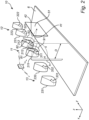
- Fig. 1 shows a perspective view of a first embodiment of a light emitting device 1 according to the invention.
- the light emitting device 1 according to the invention comprises a first light source 21 and a first lens 31 as well as a second light source 22 and a second lens 32. This applies for all embodiments of the invention.
- the first light source 21 and the first lens 31 are arranged on a first axis 41.
- the second light source 22 and the second lens 32 are arranged on a second axis 42.
- the first axis 41 and the second axis 42 intersect at a target surface 5.
- the target surface 5 is a surface which it is desired to illuminate with the light emitting device 1.
- the target surface 5 may for instance be a wall (as shown on Fig. 1 ), a ceiling or a floor.
- the first light source 21 and the second light source 22 are arranged in a distance D from a plane P in which the target surface 5 is arranged.
- the distance D is measured perpendicular to the plane P, i.e. in the direction x illustrated by the coordinate system shown in Fig. 1 .
- the distance D is thus the shortest distance between the respective light source 21, 22 and the plane P.
- the distance D is generally less than one meter.
- the first light source 21 and the first lens 31 and the second light source 22 and the second lens 32 are further arranged in a height h above a surface 6 extending perpendicular to the plane P.
- the height h is measured in the direction z illustrated by the coordinate system shown in Fig. 1 .
- the surface 6 may be a floor surface.
- the first axis 41 and the second axis 42 extend at an angle ⁇ with a plane H extending in parallel with and in the predefined distance D from the plane P.
- the angle ⁇ may be an acute angle with the plane H.
- the first axis 41 and the second axis 42 further intersect at or in the plane P.
- the first light source 21 and the first lens 31 and the second light source 22 and the second lens 32 are further arranged on a straight line extending in the direction y illustrated by the coordinate system shown in Fig. 1 , and thus in parallel with the plane P and the target surface 5.
- the first light source 21 and the first lens 31 and the second light source 22 and the second lens 32, respectively, are more particularly arranged beside one another in the direction y.
- the distance or free space in the direction y between the first lens 31 and the second lens 32 is generally less than 25 mm, such as between 5 and 25 mm.
- the diameter of the first lens 31 and the second lens 32 may be between 10 mm and 50 mm.
- the first light source 21 and the second light source 22 may be point light sources, or light sources having a light emitting area with, e.g., a size of 0.1 ⁇ 0.1 mm or 0.15 x 0.15 mm.
- the first light source 21 and the second light source 22 may be an LED or a plurality of LEDs, such as an RGB or an RBGW package of LEDs.
- the first light source 21 and the second light source 22 may be adapted for, in operation, emitting first light respectively second light, said first and second light being of mutually different colors.
- the light emitting device 1 comprising at least the combination of the first light source 21 with the first lens 31 for providing first light and the combination of the second light source 22 with the second lens 32 for providing second light, said combinations together may be configured to provide any suitable or desired dynamic pattern on the target surface 5, including a random pattern.
- the size of the first lens 31 and the second lens 32 may be chosen in dependence of the size of a light emitting area of at least one of the first light source 21 and the second light source 22.
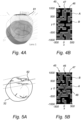
- the first lens 31 and the second lens 32 may be made of optical grade PMMA or polycarbonate or another suitable material. An example of a first lens 31 and a second lens 32 are shown in more detail in Fig. 4A and 5A , respectively.
- the first lens 31 and the second lens 32 are freeform lenses and are configured to provide mutually complementary illumination patterns on the target surface 5.
- Such complementary illumination patterns are illustrated in Figs. 4B and 5B , illustrating an exemplary illumination pattern of the respective lenses 31, 32 of Figs. 4A and 4B .
- the lens 31 provides an illumination pattern ( Fig. 4B ) having some parts/areas with a first color and/or brightness A and some parts/areas with a second color and/or brightness B
- the lens 32 provides an identical illumination pattern ( Fig. 5B ), albeit where the parts having the color and/or brightness A in Fig. 4B have the color and/or brightness B and vice versa in Fig. 5B .
- the first lens 31 and the second lens 32 may be configured to provide mutually different or even random illumination patterns.
- the brightness of bright areas is about six times higher than the brightness of dark areas.
- the illuminance pattern covers a whole illuminated area 45 and comprises a plurality of over ten of first areas 46 and a plurality of over ten of second areas 47.
- the center 48 of the whole rectangular illuminated area 45 is indicated, i.e. in this case being the intersection of the two diagonals of the rectangular illuminated area 45. Said center 48 indicates the average emission direction of a light source.
- the first lens 31 and the second lens 32 comprises a light exit surface.
- a part or all of the light exit surface of the first lens 31 and the second lens 32 may comprise an optical element 81, 82 (cf. Fig. 2 ) such as optical microstructures, e.g. lenslets, surface roughnesses or the like, or an optical foil.
- the light emitting device 1 also comprises a further (third) light source 23 adapted for, in operation, emitting light and a further (third) lens 33 associated with the further light source 23.
- the further light source 23 and the further lens 33 are optional features. More than one further light source and associated lens may in principle also be provided.
- the further light source 23 and the further lens 33 may be of any of the respective types of light sources and lenses described above.
- the further light source 23 may be of a type emitting light of a color differing from both the first light source 21 and the second light source 22 or being the same as one of the first light source 21 and the second light source 22.
- the further lens 33 may be different from, both the first lens 31 and the second lens 32.
- the further light source 23 and the further lens 33 are arranged on a further axis 43.
- the further light source 23 and the further lens 33 are oriented such that the further axis 43 intersects the first axis 41 and the second axis 42 at the target surface 5.
- the further light source 23 and the further lens 33 are arranged in a distance D from the plane P and thus from the target surface 5.
- the distance D is generally equal to or less than 1 meter.
- the further light source 23 and the further lens 33 are further arranged in a height h, for instance a height h above a floor surface 6.
- the height h is typically equal to or less than 2.5 m.
- the further axis 43 extends at an angle ⁇ , such as an acute angle ⁇ , with respect to the plane H.
- the further light source 23 and the further lens 33 are arranged beside the first light source 21 and the first lens 31 and the second light source 22 and the second lens 32, respectively, in the direction y extending in parallel with the plane P and thus with target surface 5.
- the distance or free space in the direction y between the further lens 33 and the first lens 31 and the second lens 32, respectively, is generally less than 25 mm, such as between 5 and 25 mm.
- the diameter of the further lens 33 may be between 10 mm and 50 mm.
- Fig. 2 a perspective view of a second embodiment of a light emitting device 10 according to the invention is shown.
- the light emitting device 10 differs from that described above in relation to Fig. 1 in virtue of the following features.
- the light emitting device 10 comprises three clusters 11, 12, 13 of lenses. Each cluster 11, 12, and 13 comprises two light sources and two lenses.
- the first cluster 11 comprises a first light source 211 and a first lens 311 as well as and a second light source 212 and a second lens 312.
- the second cluster 12 comprises a first light source 221 and a first lens 321 as well as and a second light source 222 and a second lens 332.
- the third cluster 11 comprises a first light source 231 and a first lens 331 as well as and a second light source 232 and a second lens 332.
- the light emitting device 1 according to Fig. 1 thus comprises only one cluster 11.
- each cluster 11, 12, 13 is in principle identical.
- each cluster comprises N first lenses, being lenses of a first type, and M second lenses, being lenses of a second type, where N is an integer being 1 or more and where M is an integer being 1 or more, and where N and M may be the same or different.
- each cluster may further comprise Q further lenses, e.g. being lenses of a further type different from the first and second type, where Q is an integer being 1 or more, and where Q may be the same as or different from one or both of N and M.
- the light emitting device 10 comprises a light mixing element 91 arranged and configured to mix light emitted from the first light source 211 of the first cluster 11 and a light mixing element 92 arranged and configured to mix light emitted from the second light source 222 of the first cluster.
- the light mixing elements 91, 92 may be arranged between the respective light source 211, 212 and lens 311, 312 or (as shown on Fig. 2 ) in front of the respective lens 311, 312.
- the light mixing elements 91, 92 each comprise a light exit surface. A part of or all of the light exit surface one or both light mixing elements 91, 92 may comprise optical microstructures, e.g. lenslets, surface roughnesses or the like, or an optical foil. Similar light mixing elements may be provided to the second cluster 12 and/or to the third cluster 13.
- the first light sources 211, 221 and 231 and the second light sources 212, 222 and 232 of each of the three clusters 11, 12 and 13 are in this embodiment configured to be tunable with respect to color, color temperature, light intensity, light flux or any combination thereof.
- the light emitting device 10 comprises a controller 7 configured to control the tunable parameter or parameters of the light sources 211, 221, 231, 212, 222 and 232.
- the controller 7 is thus in a signal transferring relationship with the respective light sources 211, 221, 231, 212, 222 and 232, for instance by use of a wired or wireless connection.
- a light emitting device according to the invention with more than three clusters. It is also feasible to provide at least one cluster of a light emitting device according to the invention with more than pairs, such as four, five or six pairs, of light sources and lenses.
- a light emitting device may also comprise an array of clusters such as the clusters 11, 12, 13 shown in Fig. 2 .
- the light emitting device 10 thus comprises an array of 1x3 clusters.
- a second row of three clusters similar to the clusters shown in Fig. 2 may be provided at another position in the Z-direction such as to provide an array of 2x3 clusters.
- any suitable size of array is possible.
- Fig. 3 a perspective view of the light emitting device 10 according to Fig. 2 and seen from another angle of view making all illuminated areas visible is shown.
- the lenses and light sources of each cluster are not shown explicitly on Fig. 3 .
- the first cluster 11 illuminates a first target area 51
- the second cluster 12 illuminates a second target area 52
- the third cluster 13 illuminates a third target area 53.
- the first and second target areas 51 and 52 are arranged with an overlap
- the second and third target areas 52 and 53 are arranged with an overlap.
- the clusters 11, 12, 13 are arranged with a pitch p seen along the direction y, where the pitch p is smaller than the size of the illuminated areas 51, 52, 53 measured in the direction y.
- Fig. 6 shows plots illustrating the irradiance created on a target surface 5 by using a light emitting device 1 according to Fig. 1 , where the optional third light source and lens are omitted, and where the first light source 21 and the second light source 22 are provided as point light sources.
- Fig. 7 shows plots similar to those of Fig. 6 and illustrating the irradiance created on a target surface 5 by using a light emitting device 1 according to Fig. 1 , where the first light source 21 and the second light source 22 are provided with a light emitting surface area of 0.1 ⁇ 0.1 mm.
- the first lens 31 and the second lens 32 used in these two examples were identical.
- the use of light sources 21 and 22 with a light emitting surface area of 0.1 ⁇ 0.1 mm provides a more uniform image with a higher irradiance level as compared to the use of point light sources 21 and 22.
- the use of point light sources 21 and 22 provides a considerably sharper image with a higher quality as compared to the use of light sources 21 and 22 with a light emitting surface area of 0.1 ⁇ 0.1 mm.
- Fig. 8 shows a circular plot illustrating the direction of the irradiance created by using a light emitting device 1 according to Fig. 1 , where the optional third light source and lens are omitted, and where the first light source 21 and the second light source 22 are provided with a light emitting surface area of 0.1 ⁇ 0.1 mm.
- Fig. 9 shows a spherical plot illustrating the spatial direction of the irradiance created by using the same light emitting device as used to produce the result illustrated in Fig. 8 .
- the use of light sources 21 and 22 with a light emitting surface area of 0.1 ⁇ 0.1 mm provides an output with a very well defined directionality, and thus provides for a particularly sharp pattern and thus resulting image on the target area 5.
- Fig. 10 shows a plot illustrating the irradiance created on a target surface 5 by using a light emitting device 1 according to Fig. 1 , where the optional third light source and lens are omitted, and where the first light source 21 and the second light source 22 are point light sources.
- Fig. 11 shows a plot similar to that of Fig. 10 and illustrating the irradiance created on a target surface 5 by using a light emitting device 1 according to Fig. 1 , where the optional third light source and lens are omitted, and where the first light source 21 and the second light source 22 have a light emitting surface area of 0.1 ⁇ 0.1 mm.
- FIG. 12 shows a plot illustrating the irradiance created on a target surface 5 by using a light emitting device 1 according to Fig. 1 , where the optional third light source and lens are omitted, and where the first light source 21 and the second light source 22 have a light emitting surface area of 0.15 x 0.15 mm.
- identical lenses 31 and 32 were used.
- Fig. 10-12 it applies that the lighter the gray tone on the plot, the higher the irradiance.
- the use of light sources 21 and 22 with a light emitting surface area of 0.1 ⁇ 0.1 mm provides a more uniform image with a higher irradiance level as compared to the use of point light sources.
- the use of point light sources 21 and 22 provides a considerably sharper image with a higher quality as compared to the use of light sources 21 and 22 with a light emitting surface area of 0.1 ⁇ 0.1 mm.
- the use of light sources 21 and 22 with a light emitting surface area of 0.1 ⁇ 0.1 mm provides a considerably sharper image with a higher quality as compared to the use of light sources 21 and 22 with a light emitting surface area of 0.15 x 0.15 mm.
- the use of light sources 21 and 22 with a light emitting surface area of 0.15 x 0.15 mm is seen to still yield a sharp image with a high quality.
Landscapes
- Engineering & Computer Science (AREA)
- General Engineering & Computer Science (AREA)
- Non-Portable Lighting Devices Or Systems Thereof (AREA)
Claims (15)
- Dispositif électroluminescent comprenant au moins une grappe (11) de sources de lumière et de lentilles, l'au moins une grappe comprenant :au moins une première source de lumière (21) et une seconde source de lumière (22), la première source de lumière et la seconde source de lumière étant conçues pour, en fonctionnement, émettre respectivement une première et une seconde lumière,au moins une première lentille (31) associée à la première source de lumière, etau moins une seconde lentille (32) associée à la seconde source de lumière, dans lequella première lentille est configurée pour créer un premier motif d'éclairement dans un plan P et la seconde lentille est configurée pour créer un second motif d'éclairement dans le plan P, dans lequella première source de lumière et la première lentille et la seconde source de lumière et la seconde lentille, respectivement, sont agencées à une distance prédéfinie D du plan P, la distance prédéfinie D étant mesurée dans une direction s'étendant perpendiculairement au plan P, dans lequella première source de lumière et la première lentille sont agencées de telle sorte que pendant le fonctionnement, une direction d'émission moyenne de la première lumière se situe le long d'un premier axe (41), et la seconde source de lumière et la seconde lentille sont agencées de telle sorte que pendant le fonctionnement, une direction d'émission moyenne de la seconde lumière se situe le long d'un second axe (42), dans lequella première source de lumière et la première lentille et la seconde source de lumière et la seconde lentille, respectivement, sont orientées de telle sorte que le premier axe et le second axe s'étendent à un angle φ avec un plan H s'étendant parallèlement et à la distance prédéfinie D du plan P et que le premier axe et le second axe se croisent au niveau ou dans le plan P, dans lequella première source de lumière et la première lentille et la seconde source de lumière et la seconde lentille, respectivement, sont en outre agencés sur une ligne droite s'étendant parallèlement au plan P et perpendiculairement à la direction dans laquelle la distance D est mesurée,dans lequel la première lentille et la seconde lentille sont des lentilles de forme libre, etdans lequel le premier motif d'éclairement et le second motif d'éclairement sont des motifs d'éclairement mutuellement différents, chaque motif d'éclairement comprenant au moins trois premières zones et au moins trois secondes zones, dans lequel les premières zones ont une première couleur et les secondes zones ont une seconde couleur différente de la première couleur et/ou les premières zones comprennent une zone la plus claire ayant une luminosité Bb et les secondes zones sont des zones sombres d'une luminosité Bd, et où Bd <= 0,25 * Bb, de préférence Bd <=0,15 * Bb, tel que Bd <= 0,1 * Bb.
- Dispositif électroluminescent selon la revendication 1, dans lequel chaque motif d'éclairement comprend au moins une première zone entourée par au moins trois secondes zones et au moins une seconde zone entourée par au moins trois premières zones.
- Dispositif électroluminescent selon l'une quelconque des revendications précédentes, dans lequel l'angle φ est un angle aigu avec le plan H s'étendant parallèlement et à la distance prédéfinie D du plan P.
- Dispositif électroluminescent selon l'une quelconque des revendications précédentes, dans lequel la première source de lumière (21) et la seconde source de lumière (22) sont l'un quelconque ou plusieurs parmi :configurées pour, en fonctionnement, émettre une lumière de couleurs mutuellement différentes,configurées pour être réglables relativement à l'un quelconque ou plusieurs parmi la couleur, la température de couleur, l'intensité lumineuse et le flux lumineux, etdes sources lumineuses ponctuelles, une DEL, une DEL ayant une zone électroluminescente carrée SL avec une taille comprise dans la plage de 0,1 x 0,1 mm <= SL <= 0,15 x 0,15 mm, une pluralité de DEL, un ensemble RVB de DEL ou un ensemble RBGW de DEL.
- Dispositif électroluminescent selon l'une quelconque des revendications précédentes, dans lequel le premier motif d'éclairement et le second motif d'éclairement mutuellement différents comprennent des motifs d'éclairement générés de manière aléatoire et des motifs d'éclairement mutuellement complémentaires.
- Dispositif électroluminescent selon l'une quelconque des revendications précédentes, dans lequel la distance prédéfinie D est égale ou inférieure à un mètre.
- Dispositif électroluminescent selon l'une quelconque des revendications précédentes, dans lequel au moins une partie d'une surface de sortie de lumière d'au moins l'une parmi la première lentille et la seconde lentille comprend l'un quelconque parmi des microstructures optiques et une feuille optique (81, 82).
- Dispositif électroluminescent selon l'une quelconque des revendications précédentes, et comprenant en outre au moins un élément de mélange de lumière (91, 92) agencé et configuré pour mélanger la lumière émise par au moins l'une parmi la première source de lumière et la seconde source de lumière.
- Dispositif électroluminescent selon la revendication 8, dans lequel au moins une partie d'une surface de sortie de lumière de l'au moins un élément de mélange de lumière (91, 92) comprend l'un quelconque parmi des microstructures optiques et une feuille optique.
- Dispositif électroluminescent selon la revendication 7 ou 9, dans lequel les microstructures optiques ou la feuille optique comprennent l'un quelconque ou plusieurs parmi des microlentilles et des rugosités de surface.
- Dispositif électroluminescent selon l'une quelconque des revendications précédentes, dans lequel l'au moins une grappe (11) comprend en outre :au moins une autre source de lumière (23) conçue pour, en fonctionnement, émettre au moins une autre lumière et au moins une autre lentille (33) associée à l'au moins une autre source de lumière, dans lequella première source de lumière et la première lentille, la seconde source de lumière et la seconde lentille et l'au moins une autre source de lumière et l'au moins une autre lentille, respectivement, sont agencées à une distance prédéfinie D du plan P, la distance prédéfinie D étant mesurée dans une direction s'étendant perpendiculairement au plan P, dans lequella première source de lumière et la première lentille sont agencées de telle sorte que, pendant le fonctionnement, la direction d'émission moyenne de la première lumière se situe le long du premier axe (41), et la seconde source de lumière et la seconde lentille sont agencées de telle sorte que, pendant le fonctionnement, la direction d'émission moyenne de la seconde lumière se situe le long du second axe (42), et l'au moins une autre source de lumière et l'au moins une autre lentille sont agencées de telle sorte que, pendant le fonctionnement, la direction d'émission de l'au moins une autre lumière se situe le long d'au moins un autre axe, dans lequella première source de lumière et la première lentille, la seconde source de lumière et la seconde lentille et l'au moins une autre source de lumière et l'au moins une autre lentille sont orientées de telle sorte que le premier axe, le second axe et l'au moins un autre axe s'étendent à un angle φ avec un plan H s'étendant parallèlement et à la distance prédéfinie D du plan P, et que le premier axe, le second axe et l'au moins un autre axe se croisent au niveau ou dans le plan P, et dans lequella première source de lumière et la première lentille, la seconde source de lumière et la seconde lentille et l'au moins une autre source de lumière et l'au moins une autre lentille, respectivement, sont en outre agencées sur une ligne droite s'étendant parallèlement au plan P et perpendiculairement à la direction dans laquelle la distance D est mesurée.
- Dispositif électroluminescent selon l'une quelconque des revendications précédentes, dans lequel l'au moins une grappe (11) comprend N premières lentilles, M secondes lentilles et, le cas échéant, Q autres lentilles, où N, M et Q sont chacun un nombre entier de 1 ou plus, et où N, M et Q peuvent être identiques ou différents.
- Dispositif électroluminescent selon l'une quelconque des revendications précédentes, dans lequel l'au moins une première lentille (31), l'au moins une seconde lentille (32) et, le cas échéant, l'au moins une autre lentille (33) sont des lentilles mutuellement différentes.
- Dispositif électroluminescent selon l'une quelconque des revendications précédentes, et comprenant en outre au moins deux grappes (11, 12, 13) de sources de lumière et de lentilles, ou comprenant en outre un réseau de grappes de sources de lumière et de lentilles.
- Luminaire comprenant un boîtier recevant au moins en partie un dispositif électroluminescent selon l'une quelconque des revendications précédentes.
Applications Claiming Priority (2)
| Application Number | Priority Date | Filing Date | Title |
|---|---|---|---|
| EP21166731 | 2021-04-01 | ||
| PCT/EP2022/058143 WO2022207562A1 (fr) | 2021-04-01 | 2022-03-28 | Dispositif électroluminescent pour créer des effets d'éclairage naturels dynamiques |
Publications (2)
| Publication Number | Publication Date |
|---|---|
| EP4314637A1 EP4314637A1 (fr) | 2024-02-07 |
| EP4314637B1 true EP4314637B1 (fr) | 2024-10-09 |
Family
ID=75362514
Family Applications (1)
| Application Number | Title | Priority Date | Filing Date |
|---|---|---|---|
| EP22718696.2A Active EP4314637B1 (fr) | 2021-04-01 | 2022-03-28 | Dispositif électroluminescent pour créer des effets d'éclairage naturel dynamique |
Country Status (4)
| Country | Link |
|---|---|
| US (1) | US12038169B2 (fr) |
| EP (1) | EP4314637B1 (fr) |
| CN (1) | CN117321336A (fr) |
| WO (1) | WO2022207562A1 (fr) |
Family Cites Families (13)
| Publication number | Priority date | Publication date | Assignee | Title |
|---|---|---|---|---|
| DE10051464B4 (de) * | 2000-10-17 | 2011-08-11 | OSRAM Opto Semiconductors GmbH, 93055 | Stufenlinse |
| US7458700B2 (en) * | 2005-03-01 | 2008-12-02 | Musco Corporation | Elective lighting fixture visors to improve playability for aerial sports |
| US7500764B2 (en) * | 2005-04-19 | 2009-03-10 | Musco Corporation | Method, apparatus, and system of aiming lighting fixtures |
| KR20080036195A (ko) * | 2005-07-13 | 2008-04-25 | 코닌클리즈케 필립스 일렉트로닉스 엔.브이. | 조명 시스템 |
| WO2009081382A1 (fr) * | 2007-12-22 | 2009-07-02 | Philips Solid-State Lighting Solutions Inc. | Luminaires à led destinés à l'éclairage architectural de grande envergure |
| US9631795B2 (en) * | 2011-06-02 | 2017-04-25 | Musco Corporation | Apparatus, method, and system for independent aiming and cutoff steps in illuminating a target area |
| DK2721656T3 (da) * | 2011-06-17 | 2019-12-16 | Signify Holding Bv | Led-lyskilde |
| WO2014045178A1 (fr) * | 2012-09-20 | 2014-03-27 | Koninklijke Philips N.V. | Dispositif d'éclairage, lentille, système et procédé associés |
| WO2015049146A1 (fr) | 2013-10-02 | 2015-04-09 | Koninklijke Philips N.V. | Système d'éclairage et méthode de commande d'un système d'éclairage |
| US10502391B2 (en) * | 2013-12-05 | 2019-12-10 | Harman Professional Denmark Aps | Light collector with a plurality of lenslets packed in an optimized dense circular pattern |
| US10201056B1 (en) * | 2014-12-02 | 2019-02-05 | Musco Corporation | Varying color of LED light using metamers |
| HUE049046T2 (hu) * | 2016-02-23 | 2020-08-28 | Signify Holding Bv | Mesterséges napfény világító |
| EP3536984A1 (fr) | 2018-03-05 | 2019-09-11 | HILTI Aktiengesellschaft | Ancre d'expansion pourvu de corps d'expansion supplémentaire |
-
2022
- 2022-03-28 EP EP22718696.2A patent/EP4314637B1/fr active Active
- 2022-03-28 CN CN202280026168.2A patent/CN117321336A/zh not_active Withdrawn
- 2022-03-28 WO PCT/EP2022/058143 patent/WO2022207562A1/fr not_active Ceased
- 2022-03-28 US US18/284,217 patent/US12038169B2/en active Active
Also Published As
| Publication number | Publication date |
|---|---|
| CN117321336A (zh) | 2023-12-29 |
| US12038169B2 (en) | 2024-07-16 |
| WO2022207562A1 (fr) | 2022-10-06 |
| EP4314637A1 (fr) | 2024-02-07 |
| US20240167662A1 (en) | 2024-05-23 |
Similar Documents
| Publication | Publication Date | Title |
|---|---|---|
| US9933137B2 (en) | Projecting light fixture with dynamic illumination of beam shaping object | |
| US9144120B2 (en) | Background light effects LED light fixture with light guided second light sources | |
| US8783904B2 (en) | Multi-beam illumination system and method of illumination | |
| EP2898259B1 (fr) | Source lumineuse à faisceau variable et procédés associés | |
| US11129250B2 (en) | Artificial sunlight luminaire | |
| US9170474B2 (en) | Efficient spatially modulated illumination system | |
| US20130039062A1 (en) | Light Fixture With Background Display Using Diffuse Pixels Between Nondiffuse Light Sources | |
| US20120319616A1 (en) | Solid state light fixture with a tunable angular distribution | |
| JP7002552B2 (ja) | 調節可能なスポットライト位置生成 | |
| US20170099470A1 (en) | Laser Arrays | |
| US10641463B2 (en) | Moving head light fixture with illuminating spherical shaped head and yoke | |
| KR101951599B1 (ko) | 입체적 이미지를 표출할 수 있는 조명장치 | |
| US12038169B2 (en) | Light emitting device for creating dynamic natural lighting effects | |
| CN112534179A (zh) | 来自不同光源的颜色混合 | |
| JP2020515017A (ja) | 照明システム及び方法 | |
| RU2705182C1 (ru) | Способ лазерного проецирования | |
| JP2005317397A (ja) | 照明器具 | |
| CN120584254A (zh) | 具有改进性能的线性照明单元 | |
| JPH08106805A (ja) | 幾何学的パターンを投影する反射体構造 |
Legal Events
| Date | Code | Title | Description |
|---|---|---|---|
| STAA | Information on the status of an ep patent application or granted ep patent |
Free format text: STATUS: UNKNOWN |
|
| STAA | Information on the status of an ep patent application or granted ep patent |
Free format text: STATUS: THE INTERNATIONAL PUBLICATION HAS BEEN MADE |
|
| PUAI | Public reference made under article 153(3) epc to a published international application that has entered the european phase |
Free format text: ORIGINAL CODE: 0009012 |
|
| STAA | Information on the status of an ep patent application or granted ep patent |
Free format text: STATUS: REQUEST FOR EXAMINATION WAS MADE |
|
| 17P | Request for examination filed |
Effective date: 20231102 |
|
| AK | Designated contracting states |
Kind code of ref document: A1 Designated state(s): AL AT BE BG CH CY CZ DE DK EE ES FI FR GB GR HR HU IE IS IT LI LT LU LV MC MK MT NL NO PL PT RO RS SE SI SK SM TR |
|
| GRAJ | Information related to disapproval of communication of intention to grant by the applicant or resumption of examination proceedings by the epo deleted |
Free format text: ORIGINAL CODE: EPIDOSDIGR1 |
|
| STAA | Information on the status of an ep patent application or granted ep patent |
Free format text: STATUS: GRANT OF PATENT IS INTENDED |
|
| GRAP | Despatch of communication of intention to grant a patent |
Free format text: ORIGINAL CODE: EPIDOSNIGR1 |
|
| DAV | Request for validation of the european patent (deleted) | ||
| DAX | Request for extension of the european patent (deleted) | ||
| INTG | Intention to grant announced |
Effective date: 20240510 |
|
| GRAS | Grant fee paid |
Free format text: ORIGINAL CODE: EPIDOSNIGR3 |
|
| GRAA | (expected) grant |
Free format text: ORIGINAL CODE: 0009210 |
|
| STAA | Information on the status of an ep patent application or granted ep patent |
Free format text: STATUS: THE PATENT HAS BEEN GRANTED |
|
| AK | Designated contracting states |
Kind code of ref document: B1 Designated state(s): AL AT BE BG CH CY CZ DE DK EE ES FI FR GB GR HR HU IE IS IT LI LT LU LV MC MK MT NL NO PL PT RO RS SE SI SK SM TR |
|
| P01 | Opt-out of the competence of the unified patent court (upc) registered |
Free format text: CASE NUMBER: APP_49257/2024 Effective date: 20240829 |
|
| REG | Reference to a national code |
Ref country code: CH Ref legal event code: EP |
|
| REG | Reference to a national code |
Ref country code: DE Ref legal event code: R096 Ref document number: 602022006713 Country of ref document: DE |
|
| REG | Reference to a national code |
Ref country code: IE Ref legal event code: FG4D |
|
| REG | Reference to a national code |
Ref country code: LT Ref legal event code: MG9D |
|
| REG | Reference to a national code |
Ref country code: NL Ref legal event code: MP Effective date: 20241009 |
|
| REG | Reference to a national code |
Ref country code: AT Ref legal event code: MK05 Ref document number: 1730944 Country of ref document: AT Kind code of ref document: T Effective date: 20241009 |
|
| PG25 | Lapsed in a contracting state [announced via postgrant information from national office to epo] |
Ref country code: NL Free format text: LAPSE BECAUSE OF FAILURE TO SUBMIT A TRANSLATION OF THE DESCRIPTION OR TO PAY THE FEE WITHIN THE PRESCRIBED TIME-LIMIT Effective date: 20241009 |
|
| PG25 | Lapsed in a contracting state [announced via postgrant information from national office to epo] |
Ref country code: NL Free format text: LAPSE BECAUSE OF FAILURE TO SUBMIT A TRANSLATION OF THE DESCRIPTION OR TO PAY THE FEE WITHIN THE PRESCRIBED TIME-LIMIT Effective date: 20241009 |
|
| PG25 | Lapsed in a contracting state [announced via postgrant information from national office to epo] |
Ref country code: IS Free format text: LAPSE BECAUSE OF FAILURE TO SUBMIT A TRANSLATION OF THE DESCRIPTION OR TO PAY THE FEE WITHIN THE PRESCRIBED TIME-LIMIT Effective date: 20250209 Ref country code: HR Free format text: LAPSE BECAUSE OF FAILURE TO SUBMIT A TRANSLATION OF THE DESCRIPTION OR TO PAY THE FEE WITHIN THE PRESCRIBED TIME-LIMIT Effective date: 20241009 Ref country code: PT Free format text: LAPSE BECAUSE OF FAILURE TO SUBMIT A TRANSLATION OF THE DESCRIPTION OR TO PAY THE FEE WITHIN THE PRESCRIBED TIME-LIMIT Effective date: 20250210 |
|
| PG25 | Lapsed in a contracting state [announced via postgrant information from national office to epo] |
Ref country code: FI Free format text: LAPSE BECAUSE OF FAILURE TO SUBMIT A TRANSLATION OF THE DESCRIPTION OR TO PAY THE FEE WITHIN THE PRESCRIBED TIME-LIMIT Effective date: 20241009 |
|
| PG25 | Lapsed in a contracting state [announced via postgrant information from national office to epo] |
Ref country code: BG Free format text: LAPSE BECAUSE OF FAILURE TO SUBMIT A TRANSLATION OF THE DESCRIPTION OR TO PAY THE FEE WITHIN THE PRESCRIBED TIME-LIMIT Effective date: 20241009 |
|
| PG25 | Lapsed in a contracting state [announced via postgrant information from national office to epo] |
Ref country code: ES Free format text: LAPSE BECAUSE OF FAILURE TO SUBMIT A TRANSLATION OF THE DESCRIPTION OR TO PAY THE FEE WITHIN THE PRESCRIBED TIME-LIMIT Effective date: 20241009 |
|
| PG25 | Lapsed in a contracting state [announced via postgrant information from national office to epo] |
Ref country code: NO Free format text: LAPSE BECAUSE OF FAILURE TO SUBMIT A TRANSLATION OF THE DESCRIPTION OR TO PAY THE FEE WITHIN THE PRESCRIBED TIME-LIMIT Effective date: 20250109 |
|
| PG25 | Lapsed in a contracting state [announced via postgrant information from national office to epo] |
Ref country code: GR Free format text: LAPSE BECAUSE OF FAILURE TO SUBMIT A TRANSLATION OF THE DESCRIPTION OR TO PAY THE FEE WITHIN THE PRESCRIBED TIME-LIMIT Effective date: 20250110 Ref country code: LV Free format text: LAPSE BECAUSE OF FAILURE TO SUBMIT A TRANSLATION OF THE DESCRIPTION OR TO PAY THE FEE WITHIN THE PRESCRIBED TIME-LIMIT Effective date: 20241009 Ref country code: AT Free format text: LAPSE BECAUSE OF FAILURE TO SUBMIT A TRANSLATION OF THE DESCRIPTION OR TO PAY THE FEE WITHIN THE PRESCRIBED TIME-LIMIT Effective date: 20241009 |
|
| PG25 | Lapsed in a contracting state [announced via postgrant information from national office to epo] |
Ref country code: PL Free format text: LAPSE BECAUSE OF FAILURE TO SUBMIT A TRANSLATION OF THE DESCRIPTION OR TO PAY THE FEE WITHIN THE PRESCRIBED TIME-LIMIT Effective date: 20241009 |
|
| PGFP | Annual fee paid to national office [announced via postgrant information from national office to epo] |
Ref country code: FR Payment date: 20250324 Year of fee payment: 4 |
|
| PG25 | Lapsed in a contracting state [announced via postgrant information from national office to epo] |
Ref country code: RS Free format text: LAPSE BECAUSE OF FAILURE TO SUBMIT A TRANSLATION OF THE DESCRIPTION OR TO PAY THE FEE WITHIN THE PRESCRIBED TIME-LIMIT Effective date: 20250109 |
|
| PG25 | Lapsed in a contracting state [announced via postgrant information from national office to epo] |
Ref country code: SM Free format text: LAPSE BECAUSE OF FAILURE TO SUBMIT A TRANSLATION OF THE DESCRIPTION OR TO PAY THE FEE WITHIN THE PRESCRIBED TIME-LIMIT Effective date: 20241009 |
|
| PGFP | Annual fee paid to national office [announced via postgrant information from national office to epo] |
Ref country code: DE Payment date: 20250528 Year of fee payment: 4 |
|
| PG25 | Lapsed in a contracting state [announced via postgrant information from national office to epo] |
Ref country code: DK Free format text: LAPSE BECAUSE OF FAILURE TO SUBMIT A TRANSLATION OF THE DESCRIPTION OR TO PAY THE FEE WITHIN THE PRESCRIBED TIME-LIMIT Effective date: 20241009 |
|
| REG | Reference to a national code |
Ref country code: DE Ref legal event code: R097 Ref document number: 602022006713 Country of ref document: DE |
|
| PG25 | Lapsed in a contracting state [announced via postgrant information from national office to epo] |
Ref country code: EE Free format text: LAPSE BECAUSE OF FAILURE TO SUBMIT A TRANSLATION OF THE DESCRIPTION OR TO PAY THE FEE WITHIN THE PRESCRIBED TIME-LIMIT Effective date: 20241009 |
|
| PG25 | Lapsed in a contracting state [announced via postgrant information from national office to epo] |
Ref country code: RO Free format text: LAPSE BECAUSE OF FAILURE TO SUBMIT A TRANSLATION OF THE DESCRIPTION OR TO PAY THE FEE WITHIN THE PRESCRIBED TIME-LIMIT Effective date: 20241009 |
|
| PG25 | Lapsed in a contracting state [announced via postgrant information from national office to epo] |
Ref country code: SK Free format text: LAPSE BECAUSE OF FAILURE TO SUBMIT A TRANSLATION OF THE DESCRIPTION OR TO PAY THE FEE WITHIN THE PRESCRIBED TIME-LIMIT Effective date: 20241009 |
|
| PG25 | Lapsed in a contracting state [announced via postgrant information from national office to epo] |
Ref country code: CZ Free format text: LAPSE BECAUSE OF FAILURE TO SUBMIT A TRANSLATION OF THE DESCRIPTION OR TO PAY THE FEE WITHIN THE PRESCRIBED TIME-LIMIT Effective date: 20241009 |
|
| PG25 | Lapsed in a contracting state [announced via postgrant information from national office to epo] |
Ref country code: IT Free format text: LAPSE BECAUSE OF FAILURE TO SUBMIT A TRANSLATION OF THE DESCRIPTION OR TO PAY THE FEE WITHIN THE PRESCRIBED TIME-LIMIT Effective date: 20241009 |
|
| PLBE | No opposition filed within time limit |
Free format text: ORIGINAL CODE: 0009261 |
|
| STAA | Information on the status of an ep patent application or granted ep patent |
Free format text: STATUS: NO OPPOSITION FILED WITHIN TIME LIMIT |
|
| PG25 | Lapsed in a contracting state [announced via postgrant information from national office to epo] |
Ref country code: SE Free format text: LAPSE BECAUSE OF FAILURE TO SUBMIT A TRANSLATION OF THE DESCRIPTION OR TO PAY THE FEE WITHIN THE PRESCRIBED TIME-LIMIT Effective date: 20241009 |
|
| 26N | No opposition filed |
Effective date: 20250710 |
|
| PG25 | Lapsed in a contracting state [announced via postgrant information from national office to epo] |
Ref country code: MC Free format text: LAPSE BECAUSE OF FAILURE TO SUBMIT A TRANSLATION OF THE DESCRIPTION OR TO PAY THE FEE WITHIN THE PRESCRIBED TIME-LIMIT Effective date: 20241009 |
|
| REG | Reference to a national code |
Ref country code: CH Ref legal event code: H13 Free format text: ST27 STATUS EVENT CODE: U-0-0-H10-H13 (AS PROVIDED BY THE NATIONAL OFFICE) Effective date: 20251023 |
|
| PG25 | Lapsed in a contracting state [announced via postgrant information from national office to epo] |
Ref country code: LU Free format text: LAPSE BECAUSE OF NON-PAYMENT OF DUE FEES Effective date: 20250328 |
|
| REG | Reference to a national code |
Ref country code: BE Ref legal event code: MM Effective date: 20250331 |
|
| PG25 | Lapsed in a contracting state [announced via postgrant information from national office to epo] |
Ref country code: BE Free format text: LAPSE BECAUSE OF NON-PAYMENT OF DUE FEES Effective date: 20250331 |
|
| PG25 | Lapsed in a contracting state [announced via postgrant information from national office to epo] |
Ref country code: CH Free format text: LAPSE BECAUSE OF NON-PAYMENT OF DUE FEES Effective date: 20250331 |
|
| PG25 | Lapsed in a contracting state [announced via postgrant information from national office to epo] |
Ref country code: IE Free format text: LAPSE BECAUSE OF NON-PAYMENT OF DUE FEES Effective date: 20250328 |