EP4314964B1 - Système de commande doté d'un dispositif de surveillance - Google Patents
Système de commande doté d'un dispositif de surveillance Download PDFInfo
- Publication number
- EP4314964B1 EP4314964B1 EP22719810.8A EP22719810A EP4314964B1 EP 4314964 B1 EP4314964 B1 EP 4314964B1 EP 22719810 A EP22719810 A EP 22719810A EP 4314964 B1 EP4314964 B1 EP 4314964B1
- Authority
- EP
- European Patent Office
- Prior art keywords
- control device
- function
- emergency stop
- machine
- assigned
- Prior art date
- Legal status (The legal status is an assumption and is not a legal conclusion. Google has not performed a legal analysis and makes no representation as to the accuracy of the status listed.)
- Active
Links
Images



Classifications
-
- G—PHYSICS
- G05—CONTROLLING; REGULATING
- G05B—CONTROL OR REGULATING SYSTEMS IN GENERAL; FUNCTIONAL ELEMENTS OF SUCH SYSTEMS; MONITORING OR TESTING ARRANGEMENTS FOR SUCH SYSTEMS OR ELEMENTS
- G05B19/00—Program-control systems
- G05B19/02—Program-control systems electric
- G05B19/04—Program control other than numerical control, i.e. in sequence controllers or logic controllers
- G05B19/048—Monitoring; Safety
-
- G—PHYSICS
- G05—CONTROLLING; REGULATING
- G05B—CONTROL OR REGULATING SYSTEMS IN GENERAL; FUNCTIONAL ELEMENTS OF SUCH SYSTEMS; MONITORING OR TESTING ARRANGEMENTS FOR SUCH SYSTEMS OR ELEMENTS
- G05B2219/00—Program-control systems
- G05B2219/20—Pc systems
- G05B2219/24—Pc safety
- G05B2219/24003—Emergency stop
-
- G—PHYSICS
- G05—CONTROLLING; REGULATING
- G05B—CONTROL OR REGULATING SYSTEMS IN GENERAL; FUNCTIONAL ELEMENTS OF SUCH SYSTEMS; MONITORING OR TESTING ARRANGEMENTS FOR SUCH SYSTEMS OR ELEMENTS
- G05B2219/00—Program-control systems
- G05B2219/30—Nc systems
- G05B2219/37—Measurements
- G05B2219/37095—Digital handheld device with data interface
-
- G—PHYSICS
- G05—CONTROLLING; REGULATING
- G05B—CONTROL OR REGULATING SYSTEMS IN GENERAL; FUNCTIONAL ELEMENTS OF SUCH SYSTEMS; MONITORING OR TESTING ARRANGEMENTS FOR SUCH SYSTEMS OR ELEMENTS
- G05B2219/00—Program-control systems
- G05B2219/30—Nc systems
- G05B2219/50—Machine tool, machine tool null till machine tool work handling
- G05B2219/50198—Emergency stop
Definitions
- the invention relates to a control device for controlling a machine or system, which has a first control device which is designed using non-safe technology and is set up to control at least one non-safety-relevant function of the machine or system, and a second control device which is designed using safe technology and is set up to control at least one safety-relevant function of the machine or system, wherein the second control device is connected to at least one input means in safe technology assigned to the second control device, which is designed for manual actuation in order to trigger the safety-relevant function.
- the DE 10 2015 206 571 B3 describes a robot handheld device, comprising a safety basic control device, a mobile terminal and a holder which is designed to attach the mobile terminal to the safety basic control device, wherein the holder has at least one adapter device which is designed to mechanically connect the mobile terminal to the safety basic control device, wherein the safety basic control device has a first handheld device part and at least one second handheld device part which is adjustable with respect to the first handheld device part, wherein the handheld device parts are adjustably coupled to one another in such a way that the handheld device parts form a contour-reduced robot handheld device in a basic arrangement and in a contour-extended receiving arrangement in which the second handheld device part is detachable from the first
- the handheld control device part is arranged displaceably from the basic arrangement, and the robot handheld control device is designed to accommodate the mobile terminal device through the adapter device.
- the DE 10 2017 108316 A1 relates to a method for operating a machine with a first handheld control device for non-safety-related machine control and a second handheld control device for safety-related machine control, wherein both handheld control devices can exchange control signals.
- the DE 10 2016 208811 B3 relates to a mobile security basic control device with a coding device for a mobile terminal with a multi-touch screen.
- the device has a housing with a holder that can be attached to a mobile terminal.
- the device also has a coding device with which the device plugged into the control device can automatically transmit a code identifying it to the terminal control via the touch screen.
- the object of the invention is to provide a control device for controlling a machine or system, by means of which the operating properties for controlling the machine or system are extended.
- the second control device can comprise at least one second input means as input means, wherein the first control device comprises at least one first input means.
- the second control device can be connected to an emergency stop switching means.
- the at least one second switching means can be an emergency stop switching means.
- the second switching means can also be, for example, a monitoring means or sensor means arranged separately from the second control device, such as a safety laser scanner.
- each input means or switching means in particular a second input means, it can be indicated, for example by a light source such as a yellow or red LED, in spatial proximity or directly on the respective input means, whether the input means which is connected to the first control device or the second control device is in its functional operating state in the respective connection mode, is in its non-functional operating state, and/or is connected to the second control device in a safe mode of operation, i.e. in safe technology, or is connected to the first control device in a non-safe mode of operation, i.e. in safe technology.
- a light source such as a yellow or red LED
- the control device for controlling the machine or system can be combined in a single control unit. Alternatively, the control device can be distributed across several devices or control housings.
- the control device can in particular consist of several control devices that form a common Control system. Connecting several control devices can in particular mean that different control units are coupled via electrical connections, so that a control device can communicate with another control device, in particular can send and/or receive, in particular exchange, data and/or signals.
- the control device can also comprise a local control unit, which can be arranged in a fixed location, and also comprise a portable control unit, which is portable or mobile, and in particular can be carried by a person from one place to another.
- individual logical control components can optionally be formed in a local control unit or in a portable control unit. Different control units can communicate with each other either wired or wirelessly, in particular via a radio connection.
- the second control device which is designed using safe technology, is a safety-related control system that meets the relevant safety standards.
- the relevant safety standards can be in particular ISO 13849-1 and IEC 62061-1.
- ISO 10218-1 can also be used.
- the second control device is designed using safe technology in particular when functionally critical components are redundant or even diverse.
- the second control device, which is designed using safe technology is in particular set up to query at least one switching state of an emergency stop switching device, an operating mode selector switch and/or at least one Consent button, which can be one of the second input devices.
- the emergency stop switching device is the main switching element of an electrical emergency stop device or an emergency stop facility or an emergency stop switch.
- This generally comprises a manually operated electrical switch which is used to put a machine or system assigned to the emergency stop switching device into a safe state when operated by a person in the event of danger.
- the emergency stop switching device is connected to an electrical control device, i.e. the second control unit, which records the switching states of the emergency stop device and, depending on this, triggers an emergency stop function which puts the machine or system into a safe state.
- an electrical control device i.e. the second control unit
- Safety functions of electric drives are defined, for example, in EN / IEC 61800-5-2 and include several types of safe operational stops, such as STO (Safe torque off), SS1 (Safe stop 1) and SS2 (Safe stop 2).
- STO Safe torque off
- SS1 Safe stop 1
- SS2 Safe stop 2
- Safety stop functions of machines in general are defined, for example, in EN / IEC 60204-1 and are referred to there as stop category 0, stop category 1 and stop category 2.
- the electrical emergency stop switch can be used to trigger emergency stop functions of a machine or system, for example in accordance with EN / IEC 61800-5-2 or EN / IEC 60204-1.
- the machine or system in question can have a safety control device or be connected to such a safety control device, which in turn is connected to the corresponding electrical emergency stop device.
- a concrete example of machines that have to meet corresponding safety requirements are industrial robots, which according to DIN EN ISO 10218-1 must be equipped with an emergency stop device in accordance with EN / IEC 60204-1 and DIN EN ISO 13850.
- the enabling switch is generally a three-stage switch that can have three different switching positions. In a middle switching position, the switching contacts of the enabling switch are electrically closed, which corresponds to a switching state of the enabling switch in which the machine or system can be put into operation or is in operation.
- the middle switching position is an unstable switching position, i.e. the enabling switch only has this switching position when a person holds the enabling switch pressed, for example with their hand or at least one finger. If, on the other hand, the enabling switch is released, the enabling switch automatically changes to its released switching position, in which the electrical switching contacts are open. In an open switching state, the machine or system is immediately and automatically transferred to a safe state.
- the enabling switch In the third switching position of the enabling switch, its actuating element is pressed through, i.e. the enabling switch is then in its pressed through switching position.
- This third switch position ensures that in the event of a dangerous situation in which an operator of the machine or system panics and does not let go of the enabling switch, but instead presses it more forcefully than is necessary to start the machine or system due to a human reflex, if the enabling switch is to be held in its middle switch position, which is an unstable switch position.
- the enabling switch can therefore be designed in accordance with IEC 60947-5.
- the enabling switch must be designed using safe technology in accordance with applicable regulations.
- the operating mode selector switch can, for example, be a multi-stage rotary knob and/or a key switch that can be moved to one of several switch positions, with each individual switch position of the operating mode selector switch being assigned a predetermined, separate safety-relevant functionality.
- the operating mode selector switch can be used to switch between automatic operation, a first inching operation and a second inching operation.
- Such an operating mode selector switch must be designed using safe technology in accordance with applicable regulations.
- Other second input devices can be not only manually operated hand buttons or hand switches, but also floor mats, door position sensors or laser scanners, for example for intrusion protection, for example on hydraulic presses, which each monitor certain states on the machine or system using safe technology.
- the first control device which is designed in non-safe technology, represents a general control system, which is only designed according to general technical rules and in particular does not meet the requirements stipulated by the relevant safety standards.
- the relevant safety standards can be in particular ISO 13849-1 and IEC 62061-1.
- ISO 10218-1 can also be used.
- the first control device is designed using non-safe technology in particular if functionally critical components are neither redundant nor diverse.
- control device in particular having a monitoring device which is designed and configured to monitor the emergency stop switching means for its functional state in such a way that the monitoring device connects the at least one second input means to the first control device in an activated functional state of the emergency stop switching means, by means of which the machine or system is transferred to a safe state, in such a way that non-safety-relevant functions of the machine or system can be triggered by manually actuating the second input means as long as the second control device, in particular the emergency stop switching means, is in the non-functional operating state in which the input means is not connected to a machine or system as an intended safety switching means, a control device for controlling a machine or system is created by which the operating properties for controlling the machine or system are expanded.
- the monitoring device can be part of the second control device or can be a control unit separate from the second control device and/or the first control device.
- the emergency stop switching means regardless of whether it is already connected to the second control device or not, has a first switching state in an unactuated first operating position of its emergency stop control part, which characterizes the non-activated functional state of the emergency stop switching means, and a second switching state in an actuated second operating position of its emergency stop control part, which characterizes the activated functional state of the emergency stop switching means.
- the emergency stop switching means can, for example, have electrical switching contacts which are open in the first switching state, so that the emergency stop switching means interrupts a circuit, and which are closed in the second switching state, so that the emergency stop switching means closes a circuit.
- the functional operating state of the emergency stop switching device is characterized in particular by the fact that when the emergency stop control element is actuated, i.e. when the activated functional state of the emergency stop switching device is initiated, the machine or system assigned to the emergency stop switching device carries out the desired or required operating stop or emergency stop, if necessary controlled by the second control device.
- any additional second switching means (and also the emergency stop switching means itself) are no longer in their intended use. Therefore, according to the technical solution according to the invention, these second switching means can be used for other purposes. This second and in this respect new use can in particular be a use that does not necessarily have to be carried out using safe technology.
- the second switching means which have lost their previous safety function when the machine or system is safely stopped, can now be used according to the invention to control other functions, in particular functions not designed using safe technology, which can be predefined and/or programmed or selected in advance. This is clearly described below using the example of an enabling button. However, the technical solutions described in this context are also applicable in their functional content to other second input devices in an analogous manner.
- the associated machine or system Since the associated machine or system is in a safe state when the emergency stop switch is activated, ie it is in the emergency stop state, the original functionality of the enabling button in the sense of IEC 60947-5 is no longer available.
- a machine operator such as a robot programmer, makes changes wants to carry out changes to a robot program, for example if incorrectly programmed movements have been programmed for the robot, he may want to edit text in command lines of the robot program. To do this, it is common to want to switch between lines of the robot program in order to activate a specific program line and edit it, i.e. to change the text.
- the first control device can be set up in such a way that manually pressing the consent button causes a cursor in the lines of the robot program to jump to the next higher program line.
- This new functionality can be predetermined in terms of control technology, i.e. programmed in.
- this new functionality can be assigned by the user or programmer themselves, for example, or selected from a number of several predetermined, possible functionalities.
- the first control device is additionally set up in such a way that by manually pressing the enabling button, the cursor jumps to the next lower program line in the lines of the robot program.
- This additional second new functionality can be predetermined in terms of control technology, i.e. programmed in.
- this additional second new functionality can be assigned by the user or the programmer themselves, for example, or selected from a number of several predefined, possible functionalities.
- An alternative Functionality can be, for example, a command to confirm an input, which in the general computer technology environment is referred to as a "select" or "return” or "input”. Jumping between program lines can be understood in the general computer technology environment as a "next" command.
- a newly assigned second input device can be used to search through multiple objects and then select a specific object in the sense of object-oriented programming.
- the object in its programmatic representation can either be a virtual object, for example an element of a list, or it can be assigned to a real object, such as a machine, in particular a robot.
- a portable handheld control device is controlled by a person, which handheld control device can optionally be assigned to a specific machine or robot. If the machine or robot, which was previously connected to the handheld control device in terms of safety control technology, is Activating an emergency stop switch on the portable handheld device brings the device into a safe state, one of the second input devices on the portable handheld device, for example its enabling button, can be used to switch the portable handheld device to another machine or robot in the system by means of a manual input on it, i.e. to initiate the control system so that the portable handheld device connects to one of the other machines or robots after the emergency stop of one machine or robot.
- the enabling button for example, by repeatedly pressing (not pressing all the way through) the enabling button, you can jump from one machine to the next machine in sequence or jump from one robot to the next robot. If the machine or robot that is started is the one that is to be connected to the handheld control unit, this machine or robot can be selected or activated by pressing (not just pressing) the same enabling button, ie the handheld control unit can actually be connected to this machine or robot in terms of control.
- the monitoring device can remove or take away the repurposed functionality from the second input means so that the second input means in question regains its original safety-related functionality.
- a conversion of the functionality of a second input means that is essentially safety-related into a general, in particular non-safety-related input means, can be particularly useful if the input device or the handheld control device in question has only a few different input means, as is the case in particular with a robot control device mentioned at the outset, as is the case for example in DE 10 2015 206 571 B3 described.
- the monitoring device can be configured to send a signal to the first control device when the second control device, in particular the emergency stop switching means, is in its activated functional state, wherein the first control device assigns a predetermined function to the at least one second input means based on the signal received from the monitoring device, such that the assigned function is executed when the at least one second input means is manually actuated.
- the monitoring device causes the second input device, which was previously assigned to a certain safety-relevant function, to be assigned a different function, in particular a non-safety-relevant function.
- a non-safety-relevant function i.e. a new function.
- two or more second Input means are each assigned a non-safety-relevant function, ie a new function is assigned.
- non-safety-relevant function types can be specified, from which either a preselected, non-safety-relevant function type is automatically activated by program control, or a permanently stored non-safety-relevant function type is automatically activated.
- the non-safety-relevant function type can therefore comprise a largely arbitrary control command or several control commands that can be interpreted, ie recognized and executed by the first control device.
- the non-safety-relevant types of functions can be, for example, or include programmatic commands.
- This can be, for example, a jump command, in the form of a programmatic "next" command, or an execution command, in the form of a programmatic "select" command, "enter” command or "execute” command.
- the jump command can be used to switch from a first menu of a graphical user interface of a handheld device to another second menu.
- a jump command it is also possible to switch from one menu item to another menu item within a menu of the graphical user interface of the handheld device.
- a selected menu item can be activated for execution, for example. This can be done, for example, using another second input device in the sense of the invention.
- the first control device can be programmed to assign the at least one second input means to assign a specific function from a set of several different possible functions. Such a configurable assignment can be made by automatically selecting or initializing a desired function that was previously selected, set or configured manually or programmatically.
- the assignment of a specific non-safety-relevant function type to a specific second input device can be configurable.
- a user of the operating device such as a robot programmer, can thus determine the desired behavior of the second input device after the emergency stop switch is activated.
- the behavior of the second input device after the emergency stop switch is activated can, for example, be predefined at the factory or implemented in the control device according to the customer's wishes.
- the at least one second input means can thus be formed on a hand-held operating device separate from the machine or the system, which also has the emergency stop switching means, which in its functional operating state is connected to the machine or the system in terms of control technology in order to bring the machine or the system into a safe state in the connected state when the emergency stop switching means has its activated functional state, wherein in the activated functional state of the emergency stop switching means the predetermined function is assigned or is directly assigned to the at least one second input means, so that when the second input means is manually actuated after activation of the emergency stop switching means the associated function can be triggered by the first control device.
- the machine or system is immediately shut down, i.e. stopped and secured against restarting, as required by the relevant standards.
- the at least one second input means can be an enabling button of the handheld control unit.
- the first control device can be designed and configured to assign a predetermined first function to the at least one enabling button in the activated functional state of the second control device, in particular the emergency stop switching means, so that this assigned first function is triggered when the enabling button is simply pressed, and to assign a predetermined second function to the same enabling button, which is different from the first function, so that the assigned second function is triggered when the enabling button is pressed all the way through.
- the first control device is set up in such a way that by manually pressing the consent button, a cursor in the lines of the robot program or a marking, which is formed by graphically, in particular color-highlighting a line of the robot program, jumps to the next higher program line. It can also be provided, for example, that the first control device is additionally set up in such a way that by manually pressing the consent button, the cursor or the marking in the lines of the robot program jumps to the next lower program line.
- the handheld control device can accordingly have a first enabling button and at least one further enabling button, and the first control device can be designed and set up, in the activated functional state of the second control device, in particular the emergency stop switching means, to assign a predetermined first function to the first enabling button, so that this assigned first function is triggered when the enabling button is simply pressed, and/or to assign a predetermined second function to the same enabling button, which differs from the first function, so that the assigned second function is triggered when the enabling button is pressed all the way through, and the first control device is designed and set up, in the activated functional state of the second control device, in particular the emergency stop switching means, to assign a predetermined further function to the further enabling button, which differs from the first function and the second function of the first enabling button, so that this assigned further function is triggered when the further enabling button is simply pressed and/or the further enabling button is pressed all the way through.
- the at least one second input means can be an operating mode selector switch of the handheld device and the first control device can be designed and configured to assign a predetermined function to the at least one operating mode selector switch in the activated functional state of the second control device, in particular the emergency stop switching means, so that this assigned function is triggered when the operating mode selector switch is switched manually.
- An example of a new functionality assigned to such an operating mode selector switch can be such that a selection direction can be determined via the switching position of the operating mode selector switch.
- a first switching position of the operating mode selector switch can be assigned the functionality "move up” and a second switching position of the operating mode selector switch can be assigned the functionality "move down”.
- These directions of movement then determine how a cursor or a marker behaves on a graphic display when, for example, the enabling button is pressed to trigger the jump functionality, depending on the switching position of the operating mode selector switch, either in the sense of a cursor jump up, according to the first switching position of the operating mode selector switch, or in the sense of a cursor jump down, according to the second switching position of the operating mode selector switch.
- the at least one second input means may optionally also be the emergency stop button of the handheld control device itself, wherein the first control device is designed and can be set up to assign a predetermined function to the emergency stop switching device when the emergency stop switching device is in the activated functional state, so that this assigned function is triggered when the emergency stop switching device is actuated.
- an additional new functionality can be configured by having a number of manual operations per specified time unit trigger a specific functionality. This can be implemented, for example, in the sense of a so-called "double click".
- the machine can, as already mentioned in exemplary embodiments, be a robot, and/or the system can comprise several robots, wherein at least one of the robots can be controlled by the handheld control device.
- a robot 1a is shown as a concrete embodiment of a machine 1 or a component of a system 2.
- the robot 1a comprises a Control device 3, which is designed and configured to control the robot 1a and, in particular, to automatically bring it into a safe state when an emergency stop is triggered, in particular to shut it down or to stop it, i.e. to stop it.
- a first handheld control device 4.1 is connected to the control device 3 by wire.
- the first handheld control device 4.1 is equipped with a first electrical emergency stop switching means 5.1, a first operating mode selector switch 6.1 and several enabling buttons 7.1.
- the first handheld control device 4.1 also comprises several first input means 8.1, which are configured to trigger non-safety-relevant functions.
- the machine 1 can accordingly be a robot 1a, in particular a robot 1a from a number of several robots of a system 2, wherein at least one of the robots 1a can be controlled by the handheld control device 4.1 and/or 4.2.
- a wireless, second handheld device 4.2 is also connected to the control device 3.
- the second handheld device 4.2 is equipped with a second electrical emergency stop switching device 5.2, a second operating mode selector switch 6.2 and several enabling buttons 7.2. Both the second emergency stop switching device 5.2, the second operating mode selector switch 6.2 and the several enabling buttons 7.2 each form a second input device 8.2 of the handheld device 4.2.
- the second handheld device 4.2 optionally also comprises several first input devices 8.1, which are configured to trigger non-safety-relevant functions.
- the second handheld device 4.2 is a special version that is designed in two parts and has a comprises a basic safety control device 9 designed using secure technology, to which a commercially available tablet computer 10 is connected, which is designed using non-secure technology.
- the tablet computer 10 can additionally have electro-mechanical input means 8.3 and/or software input means (so-called touch keys) displayed on a touchscreen 10a of the tablet computer 10.
- the at least one second input means 8.2 can be formed on a hand-held operating device 4.1, 4.2 separate from the machine 1 or the system 2, which also has the emergency stop switching means 5.1, 5.2, which in its functional operating state is connected to the machine 1 or the system 2 in terms of control technology, in order to bring the machine 1 or the system 2 into a safe state in the connected state when the emergency stop switching means 5.1, 5.2 has its activated functional state, and in the activated functional state of the emergency stop switching means 5.1, 5.2 the predetermined function is assigned to the at least one second input means 8.2, so that when the second input means 8.2 is manually operated, the assigned function can be triggered by the first control device 11, which in Fig.2 shown.
- the monitoring device 13 is designed to send a signal to the first control device 11 when the emergency stop switching means 5.1, 5.2 is in its activated functional state and the first control device 11 assigns a predetermined function to the at least one second input means 8.2 based on the signal received from the monitoring device 13, such that the assigned function is carried out when the at least one second input means 8.2 is manually actuated.
- the at least one second input means can thus also be the operating mode selector switch 6.1, 6.2 of the handheld control device 4.1, 4.2, wherein the first control device 11 is designed and configured to assign a predetermined function to the at least one operating mode selector switch 6.1, 6.2 in the activated functional state of the emergency stop switching means 5.1, 5.2, so that when the operating mode selector switch 6.1, 6.2 is switched manually, this assigned function is triggered.
- the at least one second input means 8.2 may even be the emergency stop button 5.1, 5.2 of the handheld device 4.1, 4.2 itself, wherein the first control device 11 is designed and configured to assign a predetermined function to the emergency stop switching means 5.1, 5.2 or another emergency stop switching means 5.1, 5.2 of another handheld device 4.1, 4.2 in the activated functional state of the emergency stop switching means 5.1, 5.2, so that when this emergency stop switching means 5.1, 5.2 is actuated, the assigned function is triggered.
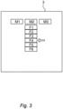
- the first control device 11 can be programmed to assign a specific function (F4) from a set of several different possible functions (F1 to F6) to the at least one second input means 8.2 if the specific function (F4) was selected manually or automatically by program control.
- the first control device 11 can be designed and configured to assign a predetermined first function to the at least one enabling button 7.1, 7.2 in the activated functional state of the emergency stop switching means 5.1, 5.2, so that this assigned first function is triggered when the enabling button 7.1, 7.2 is simply pressed, and to assign a predetermined second function to the same enabling button 7.1, 7.2, which is different from the first function, so that the assigned second function is triggered when the enabling button 7.1, 7.2 is pressed all the way through.
- buttons 7.1, 7.2 in conventional designs in addition to their electrical working contacts AK1, which are switched in such a way that they are closed in the pressed state Z1 and open both in the non-pressed state Z0 and in the pressed state Z2, can also be used, also have auxiliary contacts HK1, HK2, which, due to their individual switching configurations, allow an electrical query that makes it possible to determine whether the enabling button 7.1, 7.2 is in its non-pressed state Z0 or in its pressed state Z2. This is shown schematically in Fig. 4 shown.
- the handheld control unit 4.1, 4.2 can have a first enabling button 7.1 and at least one further enabling button 7.3, as is particularly shown in Fig. 5 is shown, wherein the first control device 11 is designed and set up, in the activated functional state of the emergency stop switching means 5.1, 5.2, to assign a predetermined first function to the first enabling button 7.1, so that when the first enabling button 7.1 is simply pressed, this assigned first function is triggered, and/or to assign a predetermined second function to the same enabling button 7.1, which differs from the first function, so that when the first enabling button 7.1 is pressed, the assigned second function is triggered, and the first control device 11 is designed and set up, in the activated functional state of the emergency stop switching means 5.1, 5.2, to assign a predetermined further function to the further enabling button 7.3, which differs from the first function and the second function of the first enabling button 7.1, so that when the further enabling button 7.3 is simply pressed and/or when the further enabling button
Landscapes
- Physics & Mathematics (AREA)
- General Physics & Mathematics (AREA)
- Engineering & Computer Science (AREA)
- Automation & Control Theory (AREA)
- Safety Devices In Control Systems (AREA)
Claims (10)
- Arrangement de commande destiné à commander une machine (1) ou une installation (2), comprenant :- un premier dispositif de commande (11), qui est réalisé dans une technique non sûre et est conçu pour commander au moins une fonction de la machine (1) ou de l'installation (2) qui n'est pas importante pour la sécurité,- un deuxième dispositif de commande (12), qui est réalisé dans une technique sûre et qui est conçu pour commander au moins une fonction de la machine (1) ou de l'installation (2) qui est importante pour la sécurité, le deuxième dispositif de commande (12) étant relié en technique sûre à au moins un deuxième moyen de saisie (8.2) associé au deuxième dispositif de commande (12), lequel est configuré pour être actionné manuellement afin de déclencher la fonction importante pour la sécurité, caractérisé par- un dispositif de surveillance (13), qui est configuré et conçu pour surveiller l'état de fonctionnement du deuxième dispositif de commande (12), de telle sorte que le dispositif de surveillance (13), dans un état de fonctionnement activé du deuxième dispositif de commande (12), par lequel la machine (1) ou l'installation (2) est transférée dans un état sécurisé, relie l'au moins un deuxième moyen de saisie (8.2) associé au deuxième dispositif de commande (12) avec le premier dispositif de commande (11) de telle sorte que les fonctions de la machine (1) ou de l'installation (2) qui ne sont pas importantes pour la sécurité peuvent être déclenchées par l'actionnement manuel de l'au moins un deuxième moyen de saisie (8.2) tant que le deuxième dispositif de commande (12) se trouve dans son état de fonctionnement activé, dans lequel l'au moins un deuxième moyen de saisie (8.2) n'est pas raccordé à la machine (1) ou à l'installation (2) en tant que moyen de commutation de sécurité conforme à la destination.
- Arrangement de commande selon la revendication 1, caractérisé en ce que le dispositif de surveillance (13) est conçu pour envoyer un signal au premier dispositif de commande (11) lorsque le deuxième dispositif de commande (12), en particulier le moyen de commutation d'arrêt d'urgence (5.1, 5.2), se trouve dans l'état de fonctionnement activé et le premier dispositif de commande (11), sur la base du signal reçu du dispositif de surveillance (13), attribue une fonction prédéterminée à l'au moins un deuxième moyen de saisie (8.2), de telle sorte que, lors de l'actionnement manuel de l'au moins un deuxième moyen de saisie (8.2), la fonction attribuée est exécutée.
- Arrangement de commande selon la revendication 2, caractérisé en ce que le premier dispositif de commande (11) est conçu par programmation pour attribuer à l'au moins un deuxième moyen de saisie (8.2) une fonction déterminée parmi une pluralité de plusieurs fonctions différentes possibles.
- Arrangement de commande selon l'une des revendications 1 à 3, caractérisé en ce que l'au moins un deuxième moyen de saisie (8.2) est réalisé sur un appareil portatif de conduite (4.1, 4.2) séparé de la machine (1) ou de l'installation (2), lequel possède également le moyen de commutation d'arrêt d'urgence (5.1, 5.2), lequel, dans son état opérationnel apte au fonctionnement, est raccordé à la machine (1) ou à l'installation (2) par technique de commande afin de, dans l'état raccordé, amener la machine (1) ou l'installation (2) dans un état sûr lorsque le moyen de commutation d'arrêt d'urgence (5.1, 5.2) présente son état fonctionnel activé et, dans l'état fonctionnel activé du moyen de commutation d'arrêt d'urgence (5.1, 5.2), la fonction prédéterminée est associée à l'au moins un deuxième moyen de saisie (8.2), de sorte que lors d'un actionnement manuel de l'au moins un deuxième moyen de saisie (8.2) après l'activation du moyen de commutation d'arrêt d'urgence (5.1, 5.2), la fonction associée peut être déclenchée par le premier dispositif de commande (11).
- Arrangement de commande selon la revendication 4, caractérisé en ce que l'au moins un deuxième moyen de saisie (8.2) est une touche d'assentiment (7.1, 7.2) de l'appareil portatif de conduite (4.1, 4.2).
- Arrangement de commande selon la revendication 5, caractérisé en ce que le premier dispositif de commande (11) est configuré et conçu pour, dans l'état de fonctionnement activé du deuxième dispositif de commande (12), en particulier du moyen de commutation d'arrêt d'urgence (5.1, 5.2), attribuer à l'au moins une touche d'assentiment (7.1, 7.2) une première fonction prédéterminée, de telle sorte qu'une simple pression sur la touche d'assentiment (7.1, 7.2), cette première fonction attribuée est déclenchée, et attribuer à la même touche d'assentiment (7.1, 7.2) une deuxième fonction prédéterminée, qui diffère de la première fonction, de telle sorte que lorsque la touche d'assentiment (7.1, 7.2) est entièrement enfoncée, la deuxième fonction attribuée est déclenchée.
- Arrangement de commande selon la revendication 5 ou 6, caractérisé en ce que l'appareil portatif de conduite (4.1, 4.2) possède une première touche d'assentiment (7.1, 7.2) et au moins une touche d'assentiment supplémentaire (7.3) et le premier dispositif de commande (11) est configuré et conçu pour, dans l'état de fonctionnement activé du deuxième dispositif de commande (12), en particulier du moyen de commutation d'arrêt d'urgence (5.1, 5.2), attribuer à la première touche d'assentiment (7.1, 7.2) une première fonction prédéterminée, de telle sorte qu'une simple pression sur la première touche d'assentiment (7.1, 7.2), cette première fonction attribuée est déclenchée, et/ou attribuer à la même touche d'assentiment (7.1, 7.2) une deuxième fonction prédéterminée, qui diffère de la première fonction, de telle sorte que lorsque la première touche d'assentiment (7.1, 7.2) est entièrement enfoncée, la deuxième fonction attribuée est déclenchée, et le premier dispositif de commande (11) est configuré et conçu pour, dans l'état de fonctionnement activé du deuxième dispositif de commande (12), en particulier du moyen d'arrêt d'urgence (5.1, 5.2), d'attribuer à la touche d'assentiment supplémentaire (7.3) une fonction supplémentaire prédéterminée, qui diffère de la première fonction et de la deuxième fonction de la première touche d'assentiment (7.1, 7.2), de telle sorte qu'une simple pression la touche d'assentiment supplémentaire (7.3) et/ou lorsque la touche d'assentiment supplémentaire (7.3) est entièrement enfoncée, cette fonction supplémentaire attribuée est déclenchée.
- Arrangement de commande selon la revendication 4, caractérisé en ce que l'au moins un deuxième moyen de saisie (8.2) est un sélecteur de mode de fonctionnement (6.1, 6.2) de l'appareil portatif de conduite et le premier dispositif de commande (11) est configuré et conçu pour, dans l'état de fonctionnement activé du deuxième dispositif de commande (12), en particulier du moyen de commutation d'arrêt d'urgence (5.1, 5.2), attribuer à l'au moins un sélecteur de mode de fonctionnement (6.1, 6.2) une fonction prédéterminée, de telle sorte que lors d'une permutation manuelle du sélecteur de mode de fonctionnement (6.1, 6.2), cette fonction attribuée est déclenchée.
- Arrangement de commande selon la revendication 4, caractérisé en ce que l'au moins un deuxième moyen de saisie (8.2) est le bouton d'arrêt d'urgence (5.1, 5.2) de l'appareil portatif de conduite (4.1, 4.2) lui-même et le premier dispositif de commande (11) est configuré et conçu pour, dans l'état de fonctionnement activé du moyen de commutation d'arrêt d'urgence (5.1, 5.2), attribuer au moyen de commutation d'arrêt d'urgence (5.1, 5.2) une fonction prédéterminée, de telle sorte que lors d'un actionnement du moyen de commutation d'arrêt d'urgence (5.1, 5.2), cette fonction attribuée est déclenchée.
- Arrangement de commande selon l'une des revendications 4 à 9, caractérisé en ce que la machine (1) est un robot (1a) et/ou l'installation (2) comprend plusieurs robots (1a), au moins l'un des robots (1a) pouvant être commandé par l'appareil portatif de conduite (4.1, 4.2).
Applications Claiming Priority (2)
| Application Number | Priority Date | Filing Date | Title |
|---|---|---|---|
| DE102021108012.6A DE102021108012A1 (de) | 2021-03-30 | 2021-03-30 | Steuervorrichtung mit einer Überwachungseinrichtung |
| PCT/EP2022/058132 WO2022207557A1 (fr) | 2021-03-30 | 2022-03-28 | Système de commande doté d'un dispositif de surveillance |
Publications (2)
| Publication Number | Publication Date |
|---|---|
| EP4314964A1 EP4314964A1 (fr) | 2024-02-07 |
| EP4314964B1 true EP4314964B1 (fr) | 2025-02-19 |
Family
ID=81448605
Family Applications (1)
| Application Number | Title | Priority Date | Filing Date |
|---|---|---|---|
| EP22719810.8A Active EP4314964B1 (fr) | 2021-03-30 | 2022-03-28 | Système de commande doté d'un dispositif de surveillance |
Country Status (5)
| Country | Link |
|---|---|
| US (1) | US12517486B2 (fr) |
| EP (1) | EP4314964B1 (fr) |
| CN (1) | CN117136341A (fr) |
| DE (1) | DE102021108012A1 (fr) |
| WO (1) | WO2022207557A1 (fr) |
Families Citing this family (1)
| Publication number | Priority date | Publication date | Assignee | Title |
|---|---|---|---|---|
| CN119155202B (zh) * | 2024-11-12 | 2025-07-01 | 支付宝(杭州)信息技术有限公司 | 一种检测唤端的方法、装置、设备及介质 |
Family Cites Families (8)
| Publication number | Priority date | Publication date | Assignee | Title |
|---|---|---|---|---|
| DE102014110017A1 (de) | 2014-07-16 | 2016-01-21 | Phoenix Contact Gmbh & Co. Kg | Steuer- und Datenübertragungssystem, Gateway-Modul, E/A-Modul und Verfahren zur Prozesssteuerung |
| DE102015206478A1 (de) | 2015-04-10 | 2016-10-13 | Wobben Properties Gmbh | Windenergieanlage mit Flüssigkeitskreislauf und Komponenten dafür |
| DE102015206578B3 (de) * | 2015-04-13 | 2016-08-04 | Kuka Roboter Gmbh | Roboter-Bedienhandgerät, sowie zugehöriges Verfahren |
| DE102015206571B3 (de) | 2015-04-13 | 2016-08-04 | Kuka Roboter Gmbh | Roboter-Bedienhandgerät mit einer Adaptervorrichtung für ein mobiles Endgerät |
| CN107221461B (zh) * | 2016-03-22 | 2020-06-05 | 皇家飞利浦有限公司 | 用于个人护理器具的安全开关装置 |
| DE102016208811B3 (de) | 2016-05-20 | 2017-10-05 | Kuka Roboter Gmbh | Mobile Sicherheits-Grundsteuervorrichtung mit einer Kodiervorrichtung für ein mobiles Endgerät mit Multi-Touchscreen |
| DE102017108316B4 (de) * | 2017-04-19 | 2025-08-28 | Ningbo Schleicher Technology Group Co., Ltd. | Verfahren und mobile Handbedieneinrichtung zum Bedienen einer Maschine |
| DE102019103643A1 (de) | 2019-02-13 | 2020-08-13 | Telegärtner Elektronik GmbH | Arbeitsmaschine zum Durchführen wenigstens eines Arbeitsvorgangs |
-
2021
- 2021-03-30 DE DE102021108012.6A patent/DE102021108012A1/de active Pending
-
2022
- 2022-03-28 US US18/552,815 patent/US12517486B2/en active Active
- 2022-03-28 EP EP22719810.8A patent/EP4314964B1/fr active Active
- 2022-03-28 WO PCT/EP2022/058132 patent/WO2022207557A1/fr not_active Ceased
- 2022-03-28 CN CN202280025596.3A patent/CN117136341A/zh active Pending
Also Published As
| Publication number | Publication date |
|---|---|
| DE102021108012A1 (de) | 2022-10-06 |
| EP4314964A1 (fr) | 2024-02-07 |
| CN117136341A (zh) | 2023-11-28 |
| US12517486B2 (en) | 2026-01-06 |
| US20240184262A1 (en) | 2024-06-06 |
| WO2022207557A1 (fr) | 2022-10-06 |
Similar Documents
| Publication | Publication Date | Title |
|---|---|---|
| DE102016208811B3 (de) | Mobile Sicherheits-Grundsteuervorrichtung mit einer Kodiervorrichtung für ein mobiles Endgerät mit Multi-Touchscreen | |
| EP1419432B1 (fr) | Dispositif pour la commande d'un appareil medical, notamment d'une table d'operation mobile | |
| AT10676U1 (de) | Verfahren zum betreiben eines mobilen handbediengerätes für die abgabe oder freischaltung von potentiell gefahrbringenden steuerkommandos sowie entsprechendes handbediengerät | |
| DE10296623T5 (de) | Industrieller Roboter | |
| EP3507662B1 (fr) | Procédé de fonctionnement d'un système de commande industrielle et système de commande correspondant | |
| DE102010039540C5 (de) | Handbediengerät zum manuellen Bewegen eines Roboterarms | |
| EP3873702B1 (fr) | Procédé de fonctionnement d'un système de commande de machine et système de commande de machine | |
| EP3140083A1 (fr) | Dispositif de services et système de commande | |
| WO2020087099A1 (fr) | Procédé servant à faire fonctionner un système de commande de machine et système de commande de machine correspondant | |
| EP3064050B1 (fr) | Système de contrôle d'un appareil de travail agricole | |
| EP2098924A1 (fr) | Procédé et dispositif adaptés à la programmation et/ou la configuration d'un contrôleur de sécurité | |
| EP4314964B1 (fr) | Système de commande doté d'un dispositif de surveillance | |
| DE102016103700A1 (de) | Steuerkonsole | |
| DE202008017893U1 (de) | Vorrichtung zum Programmieren und/oder Konfigurieren einer Sicherheitssteuerung | |
| DE102012018713A1 (de) | Maschinensteuerung und Verfahren zum Steuern einer Maschine | |
| DE102007038722A1 (de) | Verfahren zum Auslösen von Aktionen einer Maschine durch sichere Eingabeelemente | |
| EP3980224B1 (fr) | Élément de commutation de sécurité pour des machines ou des robots | |
| WO2015128341A1 (fr) | Procédé pour faire fonctionner un élément de commutation sûr d'une installation | |
| EP3660609B1 (fr) | Pupitre de commande | |
| DE102008060118A1 (de) | Maschine mit aufsteckbarem Bediengerät | |
| EP2875708B1 (fr) | Système de commande pour une machine agricole | |
| DE202019103188U1 (de) | Sicherheitsschaltelement für Maschinen oder Roboter | |
| DE102008060117A1 (de) | Maschine mit Bediengerät für sicherheitsrelevante Funktionen | |
| DE102023116849A1 (de) | Steuerungssystem und Betriebsverfahren für das Steuerungssystem | |
| DE102023120061A1 (de) | Tragbares Handbediengerät und Maschinensteuerungssystem mit einem solchen Handbediengerät |
Legal Events
| Date | Code | Title | Description |
|---|---|---|---|
| STAA | Information on the status of an ep patent application or granted ep patent |
Free format text: STATUS: UNKNOWN |
|
| STAA | Information on the status of an ep patent application or granted ep patent |
Free format text: STATUS: THE INTERNATIONAL PUBLICATION HAS BEEN MADE |
|
| PUAI | Public reference made under article 153(3) epc to a published international application that has entered the european phase |
Free format text: ORIGINAL CODE: 0009012 |
|
| STAA | Information on the status of an ep patent application or granted ep patent |
Free format text: STATUS: REQUEST FOR EXAMINATION WAS MADE |
|
| 17P | Request for examination filed |
Effective date: 20230915 |
|
| AK | Designated contracting states |
Kind code of ref document: A1 Designated state(s): AL AT BE BG CH CY CZ DE DK EE ES FI FR GB GR HR HU IE IS IT LI LT LU LV MC MK MT NL NO PL PT RO RS SE SI SK SM TR |
|
| DAV | Request for validation of the european patent (deleted) | ||
| DAX | Request for extension of the european patent (deleted) | ||
| P01 | Opt-out of the competence of the unified patent court (upc) registered |
Free format text: CASE NUMBER: APP_33453/2024 Effective date: 20240605 |
|
| GRAP | Despatch of communication of intention to grant a patent |
Free format text: ORIGINAL CODE: EPIDOSNIGR1 |
|
| STAA | Information on the status of an ep patent application or granted ep patent |
Free format text: STATUS: GRANT OF PATENT IS INTENDED |
|
| INTG | Intention to grant announced |
Effective date: 20240910 |
|
| GRAS | Grant fee paid |
Free format text: ORIGINAL CODE: EPIDOSNIGR3 |
|
| GRAA | (expected) grant |
Free format text: ORIGINAL CODE: 0009210 |
|
| STAA | Information on the status of an ep patent application or granted ep patent |
Free format text: STATUS: THE PATENT HAS BEEN GRANTED |
|
| AK | Designated contracting states |
Kind code of ref document: B1 Designated state(s): AL AT BE BG CH CY CZ DE DK EE ES FI FR GB GR HR HU IE IS IT LI LT LU LV MC MK MT NL NO PL PT RO RS SE SI SK SM TR |
|
| REG | Reference to a national code |
Ref country code: GB Ref legal event code: FG4D Free format text: NOT ENGLISH |
|
| REG | Reference to a national code |
Ref country code: CH Ref legal event code: EP |
|
| REG | Reference to a national code |
Ref country code: IE Ref legal event code: FG4D Free format text: LANGUAGE OF EP DOCUMENT: GERMAN |
|
| REG | Reference to a national code |
Ref country code: DE Ref legal event code: R096 Ref document number: 502022002954 Country of ref document: DE |
|
| REG | Reference to a national code |
Ref country code: NL Ref legal event code: MP Effective date: 20250219 |
|
| PG25 | Lapsed in a contracting state [announced via postgrant information from national office to epo] |
Ref country code: RS Free format text: LAPSE BECAUSE OF FAILURE TO SUBMIT A TRANSLATION OF THE DESCRIPTION OR TO PAY THE FEE WITHIN THE PRESCRIBED TIME-LIMIT Effective date: 20250519 |
|
| PG25 | Lapsed in a contracting state [announced via postgrant information from national office to epo] |
Ref country code: FI Free format text: LAPSE BECAUSE OF FAILURE TO SUBMIT A TRANSLATION OF THE DESCRIPTION OR TO PAY THE FEE WITHIN THE PRESCRIBED TIME-LIMIT Effective date: 20250219 |
|
| PG25 | Lapsed in a contracting state [announced via postgrant information from national office to epo] |
Ref country code: PL Free format text: LAPSE BECAUSE OF FAILURE TO SUBMIT A TRANSLATION OF THE DESCRIPTION OR TO PAY THE FEE WITHIN THE PRESCRIBED TIME-LIMIT Effective date: 20250219 |
|
| PG25 | Lapsed in a contracting state [announced via postgrant information from national office to epo] |
Ref country code: ES Free format text: LAPSE BECAUSE OF FAILURE TO SUBMIT A TRANSLATION OF THE DESCRIPTION OR TO PAY THE FEE WITHIN THE PRESCRIBED TIME-LIMIT Effective date: 20250219 |
|
| REG | Reference to a national code |
Ref country code: LT Ref legal event code: MG9D |
|
| PG25 | Lapsed in a contracting state [announced via postgrant information from national office to epo] |
Ref country code: NO Free format text: LAPSE BECAUSE OF FAILURE TO SUBMIT A TRANSLATION OF THE DESCRIPTION OR TO PAY THE FEE WITHIN THE PRESCRIBED TIME-LIMIT Effective date: 20250519 Ref country code: IS Free format text: LAPSE BECAUSE OF FAILURE TO SUBMIT A TRANSLATION OF THE DESCRIPTION OR TO PAY THE FEE WITHIN THE PRESCRIBED TIME-LIMIT Effective date: 20250619 |
|
| PG25 | Lapsed in a contracting state [announced via postgrant information from national office to epo] |
Ref country code: NL Free format text: LAPSE BECAUSE OF FAILURE TO SUBMIT A TRANSLATION OF THE DESCRIPTION OR TO PAY THE FEE WITHIN THE PRESCRIBED TIME-LIMIT Effective date: 20250219 |
|
| PG25 | Lapsed in a contracting state [announced via postgrant information from national office to epo] |
Ref country code: HR Free format text: LAPSE BECAUSE OF FAILURE TO SUBMIT A TRANSLATION OF THE DESCRIPTION OR TO PAY THE FEE WITHIN THE PRESCRIBED TIME-LIMIT Effective date: 20250219 |
|
| PG25 | Lapsed in a contracting state [announced via postgrant information from national office to epo] |
Ref country code: LV Free format text: LAPSE BECAUSE OF FAILURE TO SUBMIT A TRANSLATION OF THE DESCRIPTION OR TO PAY THE FEE WITHIN THE PRESCRIBED TIME-LIMIT Effective date: 20250219 Ref country code: PT Free format text: LAPSE BECAUSE OF FAILURE TO SUBMIT A TRANSLATION OF THE DESCRIPTION OR TO PAY THE FEE WITHIN THE PRESCRIBED TIME-LIMIT Effective date: 20250620 |
|
| PG25 | Lapsed in a contracting state [announced via postgrant information from national office to epo] |
Ref country code: BG Free format text: LAPSE BECAUSE OF FAILURE TO SUBMIT A TRANSLATION OF THE DESCRIPTION OR TO PAY THE FEE WITHIN THE PRESCRIBED TIME-LIMIT Effective date: 20250219 Ref country code: GR Free format text: LAPSE BECAUSE OF FAILURE TO SUBMIT A TRANSLATION OF THE DESCRIPTION OR TO PAY THE FEE WITHIN THE PRESCRIBED TIME-LIMIT Effective date: 20250520 |
|
| PGFP | Annual fee paid to national office [announced via postgrant information from national office to epo] |
Ref country code: CH Payment date: 20250520 Year of fee payment: 4 |
|
| PG25 | Lapsed in a contracting state [announced via postgrant information from national office to epo] |
Ref country code: SE Free format text: LAPSE BECAUSE OF FAILURE TO SUBMIT A TRANSLATION OF THE DESCRIPTION OR TO PAY THE FEE WITHIN THE PRESCRIBED TIME-LIMIT Effective date: 20250219 |
|
| PG25 | Lapsed in a contracting state [announced via postgrant information from national office to epo] |
Ref country code: SM Free format text: LAPSE BECAUSE OF FAILURE TO SUBMIT A TRANSLATION OF THE DESCRIPTION OR TO PAY THE FEE WITHIN THE PRESCRIBED TIME-LIMIT Effective date: 20250219 |
|
| PG25 | Lapsed in a contracting state [announced via postgrant information from national office to epo] |
Ref country code: DK Free format text: LAPSE BECAUSE OF FAILURE TO SUBMIT A TRANSLATION OF THE DESCRIPTION OR TO PAY THE FEE WITHIN THE PRESCRIBED TIME-LIMIT Effective date: 20250219 |
|
| PG25 | Lapsed in a contracting state [announced via postgrant information from national office to epo] |
Ref country code: IT Free format text: LAPSE BECAUSE OF FAILURE TO SUBMIT A TRANSLATION OF THE DESCRIPTION OR TO PAY THE FEE WITHIN THE PRESCRIBED TIME-LIMIT Effective date: 20250219 |
|
| PG25 | Lapsed in a contracting state [announced via postgrant information from national office to epo] |
Ref country code: CZ Free format text: LAPSE BECAUSE OF FAILURE TO SUBMIT A TRANSLATION OF THE DESCRIPTION OR TO PAY THE FEE WITHIN THE PRESCRIBED TIME-LIMIT Effective date: 20250219 Ref country code: EE Free format text: LAPSE BECAUSE OF FAILURE TO SUBMIT A TRANSLATION OF THE DESCRIPTION OR TO PAY THE FEE WITHIN THE PRESCRIBED TIME-LIMIT Effective date: 20250219 |
|
| PG25 | Lapsed in a contracting state [announced via postgrant information from national office to epo] |
Ref country code: RO Free format text: LAPSE BECAUSE OF FAILURE TO SUBMIT A TRANSLATION OF THE DESCRIPTION OR TO PAY THE FEE WITHIN THE PRESCRIBED TIME-LIMIT Effective date: 20250219 |
|
| PG25 | Lapsed in a contracting state [announced via postgrant information from national office to epo] |
Ref country code: SK Free format text: LAPSE BECAUSE OF FAILURE TO SUBMIT A TRANSLATION OF THE DESCRIPTION OR TO PAY THE FEE WITHIN THE PRESCRIBED TIME-LIMIT Effective date: 20250219 |
|
| PG25 | Lapsed in a contracting state [announced via postgrant information from national office to epo] |
Ref country code: LU Free format text: LAPSE BECAUSE OF NON-PAYMENT OF DUE FEES Effective date: 20250328 |
|
| REG | Reference to a national code |
Ref country code: DE Ref legal event code: R097 Ref document number: 502022002954 Country of ref document: DE |
|
| REG | Reference to a national code |
Ref country code: BE Ref legal event code: MM Effective date: 20250331 |
|
| PG25 | Lapsed in a contracting state [announced via postgrant information from national office to epo] |
Ref country code: MC Free format text: LAPSE BECAUSE OF FAILURE TO SUBMIT A TRANSLATION OF THE DESCRIPTION OR TO PAY THE FEE WITHIN THE PRESCRIBED TIME-LIMIT Effective date: 20250219 |
|
| PLBE | No opposition filed within time limit |
Free format text: ORIGINAL CODE: 0009261 |
|
| STAA | Information on the status of an ep patent application or granted ep patent |
Free format text: STATUS: NO OPPOSITION FILED WITHIN TIME LIMIT |
|
| REG | Reference to a national code |
Ref country code: CH Ref legal event code: L10 Free format text: ST27 STATUS EVENT CODE: U-0-0-L10-L00 (AS PROVIDED BY THE NATIONAL OFFICE) Effective date: 20251231 |
|
| PGFP | Annual fee paid to national office [announced via postgrant information from national office to epo] |
Ref country code: FR Payment date: 20251231 Year of fee payment: 5 |
|
| PG25 | Lapsed in a contracting state [announced via postgrant information from national office to epo] |
Ref country code: BE Free format text: LAPSE BECAUSE OF NON-PAYMENT OF DUE FEES Effective date: 20250331 |
|
| PG25 | Lapsed in a contracting state [announced via postgrant information from national office to epo] |
Ref country code: IE Free format text: LAPSE BECAUSE OF NON-PAYMENT OF DUE FEES Effective date: 20250328 |
|
| 26N | No opposition filed |
Effective date: 20251120 |
|
| REG | Reference to a national code |
Ref country code: CH Ref legal event code: U11 Free format text: ST27 STATUS EVENT CODE: U-0-0-U10-U11 (AS PROVIDED BY THE NATIONAL OFFICE) Effective date: 20260401 |
|
| PGFP | Annual fee paid to national office [announced via postgrant information from national office to epo] |
Ref country code: GB Payment date: 20260106 Year of fee payment: 5 |
|
| PGFP | Annual fee paid to national office [announced via postgrant information from national office to epo] |
Ref country code: DE Payment date: 20260102 Year of fee payment: 5 |
|
| PGFP | Annual fee paid to national office [announced via postgrant information from national office to epo] |
Ref country code: AT Payment date: 20260301 Year of fee payment: 5 |