EP4316865B1 - Jante pour roue de véhicule - Google Patents
Jante pour roue de véhicule Download PDFInfo
- Publication number
- EP4316865B1 EP4316865B1 EP22189111.2A EP22189111A EP4316865B1 EP 4316865 B1 EP4316865 B1 EP 4316865B1 EP 22189111 A EP22189111 A EP 22189111A EP 4316865 B1 EP4316865 B1 EP 4316865B1
- Authority
- EP
- European Patent Office
- Prior art keywords
- annular portion
- wall
- central
- annular
- peripheral
- Prior art date
- Legal status (The legal status is an assumption and is not a legal conclusion. Google has not performed a legal analysis and makes no representation as to the accuracy of the status listed.)
- Active
Links
Images



Classifications
-
- B—PERFORMING OPERATIONS; TRANSPORTING
- B60—VEHICLES IN GENERAL
- B60B—VEHICLE WHEELS; CASTORS; AXLES FOR WHEELS OR CASTORS; INCREASING WHEEL ADHESION
- B60B21/00—Rims
- B60B21/02—Rims characterised by transverse section
- B60B21/026—Rims characterised by transverse section the shape of rim well
-
- B—PERFORMING OPERATIONS; TRANSPORTING
- B60—VEHICLES IN GENERAL
- B60B—VEHICLE WHEELS; CASTORS; AXLES FOR WHEELS OR CASTORS; INCREASING WHEEL ADHESION
- B60B21/00—Rims
- B60B21/02—Rims characterised by transverse section
- B60B21/028—Rims characterised by transverse section the shape of hump
-
- B—PERFORMING OPERATIONS; TRANSPORTING
- B60—VEHICLES IN GENERAL
- B60B—VEHICLE WHEELS; CASTORS; AXLES FOR WHEELS OR CASTORS; INCREASING WHEEL ADHESION
- B60B21/00—Rims
- B60B21/02—Rims characterised by transverse section
- B60B21/04—Rims characterised by transverse section with substantially radial flanges
-
- B—PERFORMING OPERATIONS; TRANSPORTING
- B60—VEHICLES IN GENERAL
- B60B—VEHICLE WHEELS; CASTORS; AXLES FOR WHEELS OR CASTORS; INCREASING WHEEL ADHESION
- B60B2900/00—Purpose of invention
- B60B2900/30—Increase in
- B60B2900/311—Rigidity or stiffness
-
- B—PERFORMING OPERATIONS; TRANSPORTING
- B60—VEHICLES IN GENERAL
- B60B—VEHICLE WHEELS; CASTORS; AXLES FOR WHEELS OR CASTORS; INCREASING WHEEL ADHESION
- B60B2900/00—Purpose of invention
- B60B2900/50—Improvement of
- B60B2900/521—Tyre mounting or removal
-
- B—PERFORMING OPERATIONS; TRANSPORTING
- B60—VEHICLES IN GENERAL
- B60B—VEHICLE WHEELS; CASTORS; AXLES FOR WHEELS OR CASTORS; INCREASING WHEEL ADHESION
- B60B2900/00—Purpose of invention
- B60B2900/50—Improvement of
- B60B2900/523—Tyre fixation on rim, e.g. fixing axially or circumferentially thereon
-
- B—PERFORMING OPERATIONS; TRANSPORTING
- B60—VEHICLES IN GENERAL
- B60Y—INDEXING SCHEME RELATING TO ASPECTS CROSS-CUTTING VEHICLE TECHNOLOGY
- B60Y2200/00—Type of vehicle
- B60Y2200/20—Off-Road Vehicles
- B60Y2200/22—Agricultural vehicles
Definitions
- the present invention relates to a wheel rim, in particular a rim for a wheel of a vehicle.
- the present invention can be advantageously applied to an agricultural vehicle.
- Another limit of the prior art lies in the fact that the structure of the rim is weakened especially in certain zones like, for example, in the welding zones of an additional element (as disclosed in WO 2017/195099 A1 ), or in the zones connected to curvature radiuses that are such as to cause relatively high necking in the step of forming the rim.
- One object of the invention is to propose a rim that is able to overcome one or more of the aforesaid limits and drawbacks of the prior art.
- One object of the invention is to provide an alternative solution to the problem of providing a wheel rim on which to assemble a tyre.
- One advantage is to make a rim onto which it is possible to fit a tyre in a particularly easy and practical manner.
- One advantage is to enable a tyre to be fitted to the rim without risk of damage to the tyre, in particular to the beads thereof.
- One advantage is gradual and reliable positioning of the tyre in a correct position on the rim during the inflation step.
- One advantage is to create a rim with a relatively robust structure, in particular a rim made in one piece (without additional elements made on a base body) and/or devoid of zones with high necking.
- One advantage is to make available a wheel rim, in particular for a vehicle wheel, which is constructionally simple and cheap.
- a wheel rim comprises an annular body with a central annular portion extending around an axis, two peripheral annular portions for coupling with the beads of a tyre and two intermediate annular portions that connect the two peripheral annular portions to the central annular portion, in which each intermediate annular portion comprises a tilted wall with an external frustoconical surface that forms an angle ⁇ with a plane that is perpendicular to the aforesaid axis, in which the angle ⁇ is less than 58°, for example comprised in the range 50° ⁇ 5°, and the central connecting wall comprises an external convex annular surface connected to the aforesaid frustoconical surface.
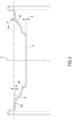
- a wheel rim has been indicated overall, in particular usable for a wheel of a vehicle like, for example, an agricultural vehicle.
- the wheel may comprise, in particular, a tyre that has to be fitted to the rim 1.
- the rim 1 comprises an annular body.
- the annular body is made in a single piece (as in the illustrated embodiment), for example in pressed sheet metal.
- the annular body may be made, in particular, by cold plastic deformation of a semifinished workpiece.
- the annular body comprises a central annular portion 2.
- the central annular portion 2 extends around an axis X.
- the axis X may substantially coincide, in particular, with the axis of rotation of the assembled wheel.
- the central annular portion 2 may comprise, in particular, an external revolution surface extending around the axis X and/or an internal revolution surface extending around the axis X (where "external” and “internal” refers to the axis X).
- the central annular portion 2 may be, as in this specific example, of cylindrical shape.
- the central annular portion 2 may be, in particular, configured for enabling a wheel hub to be inserted that will be connected to the rim (by connecting means, for example of known type).
- the central annular portion 2 may have a thickness S that is the same, in particular, as a value comprised in the range 6 ⁇ 3 mm, or in the range 6 ⁇ 2 mm, or in the range 6 ⁇ 1 mm.
- the annular body may be shaped, in particular, in a symmetrical (specular) manner around a plane Y of symmetry perpendicular to the axis X.
- the annular body comprises two peripheral annular portions 3 located on two sides opposite (in an axial direction) with respect to the central annular portion 2.
- Each peripheral annular portion 3 is more distant from the axis X than the central annular portion 2.
- the two peripheral annular portions 3 are configured for coupling with the two beads of a tyre.
- Each peripheral annular portion 3 may comprise, in particular, an edge extending radially (with reference to the axis X) configured for retaining the tyre on the rim 1 in an assembled configuration of the wheel.
- the annular body comprises two intermediate annular portions 4. Each intermediate annular portion 4 is arranged for joining the central annular portion 2 to a respective peripheral annular portion 3. Each intermediate annular portion 4 may be, in particular, more distant from the aforesaid axis X than the central annular portion 2. Each peripheral annular portion 3 may be, in particular, more distant from the aforesaid axis X than the respective intermediate annular portion 4.
- Each intermediate annular portion 4 comprises a tilted wall 41, a central connecting wall 42 and a peripheral connecting wall 43.
- the respective central connecting wall 42 may be configured, in particular, for joining the respective tilted wall 41 to the central annular portion 2.
- the respective peripheral connecting wall 43 may be configured, in particular, for joining the respective tilted wall 41 to the respective peripheral annular portion 3.
- the respective peripheral connecting wall 43 may be, in particular, more distant from the aforesaid axis X than the respective central connecting wall 42.
- the respective tilted wall 41 comprises a frustoconical surface 5 facing radially outwards, where "radially" means with reference to the aforesaid axis X.
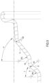
- the external frustoconical surface 5 of each tilted wall 41 forms an angle ⁇ with a plane that is perpendicular to the aforesaid axis X.
- This angle ⁇ may be, in particular, less than 60°.
- This angle ⁇ may be, in particular, less than 58°.
- This angle ⁇ may be, in particular, less than 55°.
- This angle ⁇ may be, in particular, greater than 40°.
- This angle ⁇ may be, in particular, greater than 40° and less than 60°.
- This angle ⁇ may be, as in the specific embodiment illustrated, comprised in the range 50° ⁇ 1°.
- the respective peripheral connecting wall 43 comprises a frustoconical surface 6 facing radially outwards.
- the frustoconical surface 6 of the respective peripheral connecting wall 43 forms an angle ⁇ with a direction parallel to the aforesaid axis X.
- This angle ⁇ may be, in particular, less than 10°.
- This angle ⁇ may be, as in this specific embodiment, equal to 5°.
- the frustoconical surface 6 of the respective peripheral connecting wall and the frustoconical surface 5 of the respective tilted wall 41 may form, in particular, an angle comprised between 30° and 40°, or an angle comprised in the range 35° ⁇ 3°, or an angle comprised in the range 35° ⁇ 1°.
- the frustoconical surface 6 of the respective peripheral connecting wall and the frustoconical surface 5 of the respective tilted wall 41 are coaxial to one another, both extending around the axis X.
- the respective central connecting wall 42 comprises a convex annular surface 7 facing radially outwards and/or a concave annular surface 8 facing radially inwards.
- the rim 1 may comprise, in particular, a valve hole 9 arranged on one of the two tilted walls 41.
- a convexity of the convex annular surface 7 of each central connecting wall 42 may have, in particular, a radius of curvature R1 (measured on a section plane passing through the axis X). It is possible to provide, in particular, R1 > 1.5 * S1, or R1 > 1.8 * S1, or R1 > 2.0 * S1, R1 > 2.2 * S1. It is possible to provide, in particular, R1 ⁇ 4.0 * S1, or R1 ⁇ 3.5 * S1, or R1 ⁇ 3.0 * S1, or R1 ⁇ 2.5 * S1. It is possible to provide, in particular, 1.5 * S1 ⁇ R1 ⁇ 3.0 * S1.
- R1 being comprised in the range 14 ⁇ 2 mm.
- the external frustoconical surface 6 of each peripheral connecting wall 43 may be, in particular, connected to the external frustoconical surface 5 of the respective tilted wall 41 by means of an annular connecting surface with a radius of curvature R2 (measured on a section plane passing through the axis X). According to the invention, it provides 1.5 * S2 ⁇ R2 ⁇ 2.5 * S2. It is possible to provide, in particular, 1.8 * S2 ⁇ R2 ⁇ 2.2 * S2. It is possible to provide, in particular, for R2 being comprised in the range 12 ⁇ 2 mm.
- each central connecting wall 42 may be, in particular, connected to the external frustoconical surface 5 of the respective tilted wall 41 by means of an annular connecting surface with a radius of curvature R3 (measured on a section plane passing through the axis X). It is possible to provide, in particular, 1.5 * S2 ⁇ R3 ⁇ 3.0 * S2. It is possible to provide, in particular, 1.8 * S2 ⁇ R3 ⁇ 2.5 * S2. It is possible to provide, in particular, for R3 being comprised in the range 13 ⁇ 2 mm.
- the external convex annular surface 7 of the respective central connecting wall 42 may be, in particular, connected to an external surface of the central annular portion 2 by means of an annular connecting surface with a radius of curvature R4. It is possible to provide, in particular, 1.2 * S ⁇ R10 ⁇ 2.0 * S. It is possible to provide, in particular, 1.4 * S ⁇ R10 ⁇ 1.8 * S. It is possible to provide, in particular, for R4 being comprised in the range 10 ⁇ 2 mm.
- first external connecting surface 10 connecting the annular connecting surface to the radius of curvature R3 and the annular connecting surface to the radius of curvature R1.
- the first external connecting surface 10 may be, in particular, of cylindrical shape with an axis coinciding with the axis X.
- the first external connecting surface 10 may have, in particular, a relatively reduced axial dimension, for example of a few tenths of a millimetre.
- Each first connecting external surface 10 may be, in particular, arranged between the respective convex annular surface 7 and the frustoconical surface 5 of the respective tilted wall 41.
- each intermediate annular portion 4 it is possible to provide (as in the embodiment of figure 5 ) a second external connecting surface 11 connecting the annular connecting surface to the radius of curvature R1 and the annular connecting surface to the radius of curvature R4.
- the second external connecting surface 11 may be, in particular, of frustoconical shape around the axis X, forming an angle ⁇ with a plane that is perpendicular to the axis X. This angle ⁇ may be comprised, in particular, in the range 20° ⁇ 5°, or in the range 20° ⁇ 2°.
- the second external connecting surface 11 may have, in particular, a relatively reduced axial dimension, for example of a few tenths of a millimetre.
- Each second external connecting surface 11 may be, in particular, arranged between the respective convex annular surface 7 and the central annular portion 2.
- the various sections of the annular body may have thicknesses that are the same as one another.
- the thickness S of the central annular portion 2 may be equal to the thickness S1 of the central connecting wall 42 and/or to the thickness S2 of the tilted wall 41 and/or to the thickness S3 of the peripheral connecting wall 43 and/or to the thickness S4 of the peripheral annular portion 3.
- the task of assembling the wheel is facilitated owing to the fact that the tyre is inserted into the rim practically and immediately in a position that is suitable for performing the subsequent assembly steps.
- the tyre settles so naturally and gradually as to significantly reduce the risk of damage to the tyre like, for example, abrasions or excessive stress on the beads.
- Another advantage lies in the fact that the connecting surfaces between the various sections of the annular body made by pressing a single piece by cold deformation have radiuses of curvature (R1, R2, R3, R4) that as has been established cause relatively small necking, so that the pressed annular body that is obtained is provided with great resistance to wear.
Landscapes
- Engineering & Computer Science (AREA)
- Mechanical Engineering (AREA)
- Tires In General (AREA)
Claims (12)
- Jante de roue, ladite jante comprenant un corps annulaire fait d'une seule pièce avec une partie annulaire centrale (2), deux parties annulaires périphériques (3) et deux parties annulaires intermédiaires (4), ladite partie annulaire centrale (2) s'étendant autour d'un axe (X) et étant conçue pour être disposée autour d'un moyeu de roue, lesdites deux parties annulaires périphériques (3) étant situées sur deux côtés axialement opposés à ladite partie annulaire centrale (2), chaque partie annulaire périphérique (3) étant plus éloignée dudit axe (X) que ladite partie annulaire centrale (2) et étant conçue pour s'accoupler avec un talon d'un pneu, chaque partie annulaire intermédiaire (4) étant agencée pour relier ladite partie annulaire centrale (2) à une partie annulaire périphérique (3) respective, chaque partie annulaire intermédiaire (4) comprenant une paroi inclinée (41), une paroi de liaison centrale (42) qui relie ladite paroi inclinée (41) à ladite partie annulaire centrale (2), et une paroi de liaison périphérique (43) qui relie ladite paroi inclinée (41) à la partie annulaire périphérique (3) respective, ladite paroi de liaison périphérique (43) étant plus éloignée dudit axe (X) que ladite paroi de liaison centrale (42), ladite paroi inclinée (41) comprenant une surface tronconique (5) orientée radialement vers l'extérieur, où le terme « radialement » s'entend par référence audit axe ; dans laquelle ladite surface tronconique (5) de ladite paroi inclinée (41) forme un angle α compris dans la plage α = 50° ± 4° avec un plan perpendiculaire audit axe (X) et dans laquelle ladite paroi de liaison centrale (42) comprend une surface annulaire convexe (7) orientée radialement vers l'extérieur et reliée d'un côté à ladite surface tronconique (5) de ladite paroi inclinée (41) et d'un côté axialement opposé à ladite partie annulaire centrale (2) ;
caractérisée en ce que :- ladite paroi de liaison périphérique (43) comprend une surface tronconique (6) orientée radialement vers l'extérieur et formant un angle β compris dans la plage β = 5° ± 3° avec une direction parallèle audit axe (X) ;- ladite paroi inclinée (41) a une épaisseur S2 et ladite surface tronconique (6) de ladite paroi de liaison périphérique (43) est reliée à ladite surface tronconique (5) de ladite paroi inclinée (41) au moyen d'une surface de liaison annulaire ayant un rayon de courbure R2, étant 1,5 * S2 < R2 < 2,5 * S2. - Jante selon la revendication 1, dans laquelle ledit angle α est compris dans la plage α = 50° ± 2°.
- Jante selon l'une quelconque des revendications précédentes, dans laquelle ladite paroi inclinée (41) a une épaisseur S2 et dans laquelle ladite surface annulaire convexe extérieure (7) de ladite paroi de connexion centrale (42) est reliée à ladite surface tronconique extérieure (5) de ladite paroi inclinée (41) au moyen d'une surface de liaison annulaire avec un rayon de courbure R3, étant 1,5 * S2 < R3 < 3,0 * S2, en particulier étant 1,8 * S2 < R3 < 2,5 * S2.
- Jante selon l'une quelconque des revendications précédentes, dans laquelle ladite paroi centrale de liaison (42) comprend une surface annulaire concave (8) orientée radialement vers l'intérieur.
- Jante selon l'une quelconque des revendications précédentes, dans laquelle ledit rayon de courbure R2 est de 1,8 * S2 < R2 < 2,2 * S2.
- Jante selon l'une quelconque des revendications précédentes, dans laquelle ladite paroi de liaison centrale (42) a une épaisseur S1 et dans laquelle une convexité de ladite surface annulaire convexe (7) de ladite paroi de liaison centrale (42) a un rayon de courbure R1, étant 1,5 * S1 < R1 < 3,0 * S1.
- Jante selon l'une quelconque des revendications précédentes, dans laquelle ladite partie annulaire centrale (2) a une épaisseur S et dans laquelle ladite surface annulaire convexe extérieure (7) de ladite paroi de liaison centrale (42) est reliée à une surface extérieure de ladite partie annulaire centrale (2) au moyen d'une surface de liaison annulaire ayant un rayon de courbure R4, étant 1,2 * S < R4 < 2,0 * S.
- Jante selon l'une quelconque des revendications précédentes, dans laquelle chaque partie annulaire intermédiaire (4) comprend une première surface extérieure (10) de forme cylindrique coaxiale avec ledit axe (X), ladite première surface externe (10) étant agencée pour relier ladite surface annulaire convexe (7) à ladite surface tronconique (5) de ladite paroi inclinée (41).
- Jante selon l'une quelconque des revendications précédentes, dans laquelle ledit angle β est compris dans la plage β = 5° ± 2°.
- Jante selon l'une quelconque des revendications précédentes, dans laquelle l'angle β est compris dans la plage β = 5° ± 1°.
- Jante selon l'une quelconque des revendications précédentes, dans laquelle ladite surface tronconique (6) de ladite paroi de liaison périphérique (43) et ladite surface tronconique (5) de ladite paroi inclinée (41) forment un angle compris dans la plage 35° ± 3°.
- Jante selon l'une quelconque des revendications précédentes, dans laquelle ladite surface tronconique (6) de ladite paroi de liaison périphérique (43) et ladite surface tronconique (5) de ladite paroi inclinée (41) forment un angle compris dans la plage 35° ± 1°.
Priority Applications (3)
| Application Number | Priority Date | Filing Date | Title |
|---|---|---|---|
| PL22189111.2T PL4316865T3 (pl) | 2022-08-05 | 2022-08-05 | Obręcz do koła pojazdu |
| EP22189111.2A EP4316865B1 (fr) | 2022-08-05 | 2022-08-05 | Jante pour roue de véhicule |
| US17/972,723 US12605963B2 (en) | 2022-08-05 | 2022-10-25 | Rim for vehicle wheel |
Applications Claiming Priority (1)
| Application Number | Priority Date | Filing Date | Title |
|---|---|---|---|
| EP22189111.2A EP4316865B1 (fr) | 2022-08-05 | 2022-08-05 | Jante pour roue de véhicule |
Publications (3)
| Publication Number | Publication Date |
|---|---|
| EP4316865A1 EP4316865A1 (fr) | 2024-02-07 |
| EP4316865C0 EP4316865C0 (fr) | 2025-02-26 |
| EP4316865B1 true EP4316865B1 (fr) | 2025-02-26 |
Family
ID=83398242
Family Applications (1)
| Application Number | Title | Priority Date | Filing Date |
|---|---|---|---|
| EP22189111.2A Active EP4316865B1 (fr) | 2022-08-05 | 2022-08-05 | Jante pour roue de véhicule |
Country Status (2)
| Country | Link |
|---|---|
| EP (1) | EP4316865B1 (fr) |
| PL (1) | PL4316865T3 (fr) |
Family Cites Families (4)
| Publication number | Priority date | Publication date | Assignee | Title |
|---|---|---|---|---|
| ATE537012T1 (de) * | 2008-04-04 | 2011-12-15 | Gkn Land Systems Ltd | Radaufbau |
| DE102011121596B4 (de) * | 2011-12-17 | 2020-12-03 | Volkswagen Aktiengesellschaft | Lasergeschweißtes Fahrzeugrad und Verfahren zur Herstellung eines solchen |
| ITUA20163283A1 (it) | 2016-05-09 | 2017-11-09 | Provana Quality Center Srl | Cerchio ruota di veicolo |
| GB2595217B (en) * | 2020-05-15 | 2024-05-15 | Moveero Ltd | A wheel construction |
-
2022
- 2022-08-05 PL PL22189111.2T patent/PL4316865T3/pl unknown
- 2022-08-05 EP EP22189111.2A patent/EP4316865B1/fr active Active
Also Published As
| Publication number | Publication date |
|---|---|
| EP4316865A1 (fr) | 2024-02-07 |
| EP4316865C0 (fr) | 2025-02-26 |
| PL4316865T3 (pl) | 2025-04-28 |
Similar Documents
| Publication | Publication Date | Title |
|---|---|---|
| US5533260A (en) | Method of manufacturing a vehicle wheel | |
| US20040227392A1 (en) | Fabricated vehicle wheel and method for producing same | |
| KR101523405B1 (ko) | 차량용 휠 | |
| US7104611B2 (en) | Motor vehicle wheel disc, in particular for passenger car | |
| JP5057602B2 (ja) | 車両用ホイール | |
| US7464995B2 (en) | Fabricated vehicle wheel having spokes and stiffening ribs | |
| US20130140874A1 (en) | Wheel for automobile | |
| WO2010107008A1 (fr) | Roue pour automobile | |
| JP2002240504A (ja) | スポーク車輪 | |
| JP4396910B2 (ja) | 自動車車輪用車輪ディスクと自動車車輪を形成する方法 | |
| US7014274B2 (en) | Sheet-steel wheel rim with optimized profile | |
| US6626503B2 (en) | Fabricated vehicle wheel | |
| US6629736B2 (en) | Fabricated vehicle wheel | |
| EP0944483B1 (fr) | Roue de vehicule a enjoliveur monobloc | |
| WO2003080368A1 (fr) | Roue de vehicule | |
| EP4316865B1 (fr) | Jante pour roue de véhicule | |
| US12605963B2 (en) | Rim for vehicle wheel | |
| EP3517314B1 (fr) | Methode de production d'une roue hybride pour vehicule | |
| US6354667B1 (en) | Full face vehicle wheel and method for producing same | |
| HK40103476B (en) | Rim for vehicle wheel | |
| HK40103476A (en) | Rim for vehicle wheel | |
| EP3914406B1 (fr) | Procédé de fabrication d'une roue de véhicule sans chambre à air sans soudage | |
| US6447071B1 (en) | Full face wheel with slip fit joint between disc and rim | |
| JP4499922B2 (ja) | フル・フェース車両ホイール及びその製法 | |
| US6655748B2 (en) | Fabricated vehicle wheel |
Legal Events
| Date | Code | Title | Description |
|---|---|---|---|
| PUAI | Public reference made under article 153(3) epc to a published international application that has entered the european phase |
Free format text: ORIGINAL CODE: 0009012 |
|
| STAA | Information on the status of an ep patent application or granted ep patent |
Free format text: STATUS: REQUEST FOR EXAMINATION WAS MADE |
|
| 17P | Request for examination filed |
Effective date: 20230921 |
|
| AK | Designated contracting states |
Kind code of ref document: A1 Designated state(s): AL AT BE BG CH CY CZ DE DK EE ES FI FR GB GR HR HU IE IS IT LI LT LU LV MC MK MT NL NO PL PT RO RS SE SI SK SM TR |
|
| REG | Reference to a national code |
Ref country code: HK Ref legal event code: DE Ref document number: 40103476 Country of ref document: HK |
|
| GRAP | Despatch of communication of intention to grant a patent |
Free format text: ORIGINAL CODE: EPIDOSNIGR1 |
|
| STAA | Information on the status of an ep patent application or granted ep patent |
Free format text: STATUS: GRANT OF PATENT IS INTENDED |
|
| RIC1 | Information provided on ipc code assigned before grant |
Ipc: B60B 21/04 20060101ALN20241004BHEP Ipc: B60B 21/02 20060101AFI20241004BHEP |
|
| INTG | Intention to grant announced |
Effective date: 20241028 |
|
| GRAS | Grant fee paid |
Free format text: ORIGINAL CODE: EPIDOSNIGR3 |
|
| GRAA | (expected) grant |
Free format text: ORIGINAL CODE: 0009210 |
|
| STAA | Information on the status of an ep patent application or granted ep patent |
Free format text: STATUS: THE PATENT HAS BEEN GRANTED |
|
| AK | Designated contracting states |
Kind code of ref document: B1 Designated state(s): AL AT BE BG CH CY CZ DE DK EE ES FI FR GB GR HR HU IE IS IT LI LT LU LV MC MK MT NL NO PL PT RO RS SE SI SK SM TR |
|
| REG | Reference to a national code |
Ref country code: GB Ref legal event code: FG4D |
|
| REG | Reference to a national code |
Ref country code: CH Ref legal event code: EP |
|
| REG | Reference to a national code |
Ref country code: DE Ref legal event code: R096 Ref document number: 602022011034 Country of ref document: DE |
|
| REG | Reference to a national code |
Ref country code: IE Ref legal event code: FG4D |
|
| U01 | Request for unitary effect filed |
Effective date: 20250307 |
|
| U07 | Unitary effect registered |
Designated state(s): AT BE BG DE DK EE FI FR IT LT LU LV MT NL PT RO SE SI Effective date: 20250314 |
|
| PG25 | Lapsed in a contracting state [announced via postgrant information from national office to epo] |
Ref country code: RS Free format text: LAPSE BECAUSE OF FAILURE TO SUBMIT A TRANSLATION OF THE DESCRIPTION OR TO PAY THE FEE WITHIN THE PRESCRIBED TIME-LIMIT Effective date: 20250526 |
|
| PG25 | Lapsed in a contracting state [announced via postgrant information from national office to epo] |
Ref country code: ES Free format text: LAPSE BECAUSE OF FAILURE TO SUBMIT A TRANSLATION OF THE DESCRIPTION OR TO PAY THE FEE WITHIN THE PRESCRIBED TIME-LIMIT Effective date: 20250226 |
|
| PG25 | Lapsed in a contracting state [announced via postgrant information from national office to epo] |
Ref country code: NO Free format text: LAPSE BECAUSE OF FAILURE TO SUBMIT A TRANSLATION OF THE DESCRIPTION OR TO PAY THE FEE WITHIN THE PRESCRIBED TIME-LIMIT Effective date: 20250526 Ref country code: IS Free format text: LAPSE BECAUSE OF FAILURE TO SUBMIT A TRANSLATION OF THE DESCRIPTION OR TO PAY THE FEE WITHIN THE PRESCRIBED TIME-LIMIT Effective date: 20250626 |
|
| PG25 | Lapsed in a contracting state [announced via postgrant information from national office to epo] |
Ref country code: HR Free format text: LAPSE BECAUSE OF FAILURE TO SUBMIT A TRANSLATION OF THE DESCRIPTION OR TO PAY THE FEE WITHIN THE PRESCRIBED TIME-LIMIT Effective date: 20250226 |
|
| PG25 | Lapsed in a contracting state [announced via postgrant information from national office to epo] |
Ref country code: GR Free format text: LAPSE BECAUSE OF FAILURE TO SUBMIT A TRANSLATION OF THE DESCRIPTION OR TO PAY THE FEE WITHIN THE PRESCRIBED TIME-LIMIT Effective date: 20250527 |
|
| PG25 | Lapsed in a contracting state [announced via postgrant information from national office to epo] |
Ref country code: SM Free format text: LAPSE BECAUSE OF FAILURE TO SUBMIT A TRANSLATION OF THE DESCRIPTION OR TO PAY THE FEE WITHIN THE PRESCRIBED TIME-LIMIT Effective date: 20250226 |
|
| U20 | Renewal fee for the european patent with unitary effect paid |
Year of fee payment: 4 Effective date: 20250831 |
|
| PGFP | Annual fee paid to national office [announced via postgrant information from national office to epo] |
Ref country code: TR Payment date: 20250731 Year of fee payment: 4 Ref country code: PL Payment date: 20250801 Year of fee payment: 4 |
|
| PG25 | Lapsed in a contracting state [announced via postgrant information from national office to epo] |
Ref country code: CZ Free format text: LAPSE BECAUSE OF FAILURE TO SUBMIT A TRANSLATION OF THE DESCRIPTION OR TO PAY THE FEE WITHIN THE PRESCRIBED TIME-LIMIT Effective date: 20250226 |
|
| PG25 | Lapsed in a contracting state [announced via postgrant information from national office to epo] |
Ref country code: SK Free format text: LAPSE BECAUSE OF FAILURE TO SUBMIT A TRANSLATION OF THE DESCRIPTION OR TO PAY THE FEE WITHIN THE PRESCRIBED TIME-LIMIT Effective date: 20250226 |
|
| PLBE | No opposition filed within time limit |
Free format text: ORIGINAL CODE: 0009261 |
|
| STAA | Information on the status of an ep patent application or granted ep patent |
Free format text: STATUS: NO OPPOSITION FILED WITHIN TIME LIMIT |
|
| REG | Reference to a national code |
Ref country code: CH Ref legal event code: L10 Free format text: ST27 STATUS EVENT CODE: U-0-0-L10-L00 (AS PROVIDED BY THE NATIONAL OFFICE) Effective date: 20260107 |
|
| 26N | No opposition filed |
Effective date: 20251127 |
|
| REG | Reference to a national code |
Ref country code: CH Ref legal event code: H13 Free format text: ST27 STATUS EVENT CODE: U-0-0-H10-H13 (AS PROVIDED BY THE NATIONAL OFFICE) Effective date: 20260324 |
|
| PG25 | Lapsed in a contracting state [announced via postgrant information from national office to epo] |
Ref country code: MC Free format text: LAPSE BECAUSE OF FAILURE TO SUBMIT A TRANSLATION OF THE DESCRIPTION OR TO PAY THE FEE WITHIN THE PRESCRIBED TIME-LIMIT Effective date: 20250226 |
|
| PG25 | Lapsed in a contracting state [announced via postgrant information from national office to epo] |
Ref country code: CH Free format text: LAPSE BECAUSE OF NON-PAYMENT OF DUE FEES Effective date: 20250831 |