EP4316902A1 - Konfigurationsverfahren zur stromverteilung, system, vorrichtung und speichermedium - Google Patents
Konfigurationsverfahren zur stromverteilung, system, vorrichtung und speichermedium Download PDFInfo
- Publication number
- EP4316902A1 EP4316902A1 EP21934096.5A EP21934096A EP4316902A1 EP 4316902 A1 EP4316902 A1 EP 4316902A1 EP 21934096 A EP21934096 A EP 21934096A EP 4316902 A1 EP4316902 A1 EP 4316902A1
- Authority
- EP
- European Patent Office
- Prior art keywords
- target
- power module
- input channel
- voltage
- real
- Prior art date
- Legal status (The legal status is an assumption and is not a legal conclusion. Google has not performed a legal analysis and makes no representation as to the accuracy of the status listed.)
- Pending
Links
Images

Classifications
-
- B—PERFORMING OPERATIONS; TRANSPORTING
- B60—VEHICLES IN GENERAL
- B60L—PROPULSION OF ELECTRICALLY-PROPELLED VEHICLES; SUPPLYING ELECTRIC POWER FOR AUXILIARY EQUIPMENT OF ELECTRICALLY-PROPELLED VEHICLES; ELECTRODYNAMIC BRAKE SYSTEMS FOR VEHICLES IN GENERAL; MAGNETIC SUSPENSION OR LEVITATION FOR VEHICLES; MONITORING OPERATING VARIABLES OF ELECTRICALLY-PROPELLED VEHICLES; ELECTRIC SAFETY DEVICES FOR ELECTRICALLY-PROPELLED VEHICLES
- B60L53/00—Methods of charging batteries, specially adapted for electric vehicles; Charging stations or on-board charging equipment therefor; Exchange of energy storage elements in electric vehicles
- B60L53/20—Methods of charging batteries, specially adapted for electric vehicles; Charging stations or on-board charging equipment therefor; Exchange of energy storage elements in electric vehicles characterised by converters located in the vehicle
-
- B—PERFORMING OPERATIONS; TRANSPORTING
- B60—VEHICLES IN GENERAL
- B60L—PROPULSION OF ELECTRICALLY-PROPELLED VEHICLES; SUPPLYING ELECTRIC POWER FOR AUXILIARY EQUIPMENT OF ELECTRICALLY-PROPELLED VEHICLES; ELECTRODYNAMIC BRAKE SYSTEMS FOR VEHICLES IN GENERAL; MAGNETIC SUSPENSION OR LEVITATION FOR VEHICLES; MONITORING OPERATING VARIABLES OF ELECTRICALLY-PROPELLED VEHICLES; ELECTRIC SAFETY DEVICES FOR ELECTRICALLY-PROPELLED VEHICLES
- B60L53/00—Methods of charging batteries, specially adapted for electric vehicles; Charging stations or on-board charging equipment therefor; Exchange of energy storage elements in electric vehicles
- B60L53/30—Constructional details of charging stations
-
- B—PERFORMING OPERATIONS; TRANSPORTING
- B60—VEHICLES IN GENERAL
- B60L—PROPULSION OF ELECTRICALLY-PROPELLED VEHICLES; SUPPLYING ELECTRIC POWER FOR AUXILIARY EQUIPMENT OF ELECTRICALLY-PROPELLED VEHICLES; ELECTRODYNAMIC BRAKE SYSTEMS FOR VEHICLES IN GENERAL; MAGNETIC SUSPENSION OR LEVITATION FOR VEHICLES; MONITORING OPERATING VARIABLES OF ELECTRICALLY-PROPELLED VEHICLES; ELECTRIC SAFETY DEVICES FOR ELECTRICALLY-PROPELLED VEHICLES
- B60L53/00—Methods of charging batteries, specially adapted for electric vehicles; Charging stations or on-board charging equipment therefor; Exchange of energy storage elements in electric vehicles
- B60L53/60—Monitoring or controlling charging stations
- B60L53/62—Monitoring or controlling charging stations in response to charging parameters, e.g. current, voltage or electrical charge
-
- H—ELECTRICITY
- H02—GENERATION; CONVERSION OR DISTRIBUTION OF ELECTRIC POWER
- H02J—ELECTRIC POWER NETWORKS; CIRCUIT ARRANGEMENTS OR SYSTEMS FOR SUPPLYING OR DISTRIBUTING ELECTRIC POWER; SYSTEMS FOR STORING ELECTRIC ENERGY
- H02J3/00—Circuit arrangements for AC mains or AC distribution networks
- H02J3/007—Arrangements for selectively connecting one or more loads to one or more power sources or power lines
-
- H—ELECTRICITY
- H02—GENERATION; CONVERSION OR DISTRIBUTION OF ELECTRIC POWER
- H02J—ELECTRIC POWER NETWORKS; CIRCUIT ARRANGEMENTS OR SYSTEMS FOR SUPPLYING OR DISTRIBUTING ELECTRIC POWER; SYSTEMS FOR STORING ELECTRIC ENERGY
- H02J2207/00—Details of circuit arrangements for charging or discharging batteries or supplying loads from batteries
- H02J2207/40—Details of circuit arrangements for charging or discharging batteries or supplying loads from batteries adapted for charging from various sources, e.g. AC, DC or multivoltage
Definitions
- the present disclosure relates to the field of charging technologies, and more particularly, to a configuration method, system, and device for power distribution, and a storage medium.
- each charging gun is fixedly connected to several power modules through a high-voltage wire harness. Therefore, a 120kW power module needs to be configured for a 60kW charging pile with two guns.
- an operation condition in which the two guns simultaneously outputs 60 kW is relatively rare. In most cases, at least one charging gun does not have a full power output requirement. Therefore, after the 120kW power module is equipped in practice, some power modules will be in an idle state in most cases.
- a controller configured to control the power module to output a parameter (voltage/current) needs to perform a separate voltage/current control and adjustment on each module.
- a parameter voltage/current
- embodiments of the present disclosure provide a configuration method, system, and device for power distribution, and a storage medium.
- the technical solutions will be described below.
- a configuration method for power distribution includes: controlling closing of at least one target relay in response to a power distribution request instruction, in which the closing of the at least one target relay is configured to bring a target input channel of the power distribution into communication with a target output channel of the power distribution; and traversing at least one power module until one of the at least one power module corresponding to the target input channel is determined.
- steps are performed of: controlling an output voltage of a current power module; collecting a real-time voltage at the target output channel; and determining a correspondence between the current power module and the target input channel when the real-time voltage matches with the output voltage.
- a configuration system for power distribution includes: a response module configured to control closing of at least one target relay in response to a power distribution request instruction, in which the closing of the at least one target relay is configured to bring a target input channel of the power distribution into communication with a target output channel of the power distribution; and a traversing module configured to traverse at least one power module until one of the at least one power module corresponding to the target input channel is determined.
- steps are performed of: a voltage control module configured to control an output voltage of a current power module; a collection module configured to collect a real-time voltage at the target output channel; and a relationship determination module configured to determine a correspondence between the current power module and the target input channel when the real-time voltage matches with the output voltage.
- the at least one target relay includes a plurality of target relays, and the plurality of target relays is arranged in a form of a matrix with N rows and M columns.
- the response module includes a relay closing module configured to close the plurality of the target relays arranged in the matrix of the N rows and the M columns.
- Target input channels where the plurality of target relays is located are different from each other.
- the plurality of target relays being arranged in the form of the matrix with the N rows and the M columns includes: the target relays in each of the M columns being positioned at one input channel.
- the target relays located on the one input channel are connected to N predetermined voltage monitoring devices, respectively.
- Each of the N predetermined voltage monitoring devices is configured to monitor a real-time voltage at the output channel.
- the configuration system includes: a power module connection module configured to control the power module to be connected in parallel with a set of power modules to output voltages.
- the configuration system includes, subsequent to the traversing module: a determination module configured to determine whether configurations of all power modules with the input channel are completed, end the configuration for the power distribution, in response to determining that the configurations of all power modules with the input channel are completed, and control, in response to determining that the configurations of all the power modules with the input channels are not completed, closing of a next target relay, and traverse the at least one power module until one of the at least one the power module corresponding to the target input channel is determined, until the configurations of all power modules with the input channel are completed.
- a determination module configured to determine whether configurations of all power modules with the input channel are completed, end the configuration for the power distribution, in response to determining that the configurations of all power modules with the input channel are completed, and control, in response to determining that the configurations of all the power modules with the input channels are not completed, closing of a next target relay, and traverse the at least one power module until one of the at least one the power module corresponding to the target input channel is determined, until the configuration
- the configuration system includes, when the real-time voltage mismatches with the output voltage: a first control module configured to control an output voltage of a next power module; a collection module configure to collect the real-time voltage at the target output channel; a first determination module configure to: determine whether the real-time voltage is equal to the output voltage of the next power module, determine a correspondence between the next power module and the target input channel in response to determining that the real-time voltage is equal to the output voltage of the next power module, and controlling, in response to determining that the real-time voltage is unequal to the output voltage of the next power module, the output voltage of the power module, and collecting the real-time voltage at the target output channel, until the real-time voltage value is equal to the output voltage of the power module.
- a device in yet another aspect, includes a processor and a memory.
- the memory has at least one instruction, at least one program, a code set, or an instruction set stored thereon.
- the at least one instruction, the at least one program, the code set, or the instruction set is loaded and executed by the processor to implement the above-mentioned configuration method for the power distribution.
- a storage medium has at least one instruction, at least one program, a code set, or an instruction set stored thereon.
- the at least one instruction, the at least one program, the code set, or the instruction set is loaded and executed by a processor to implement the above-mentioned configuration method for the power distribution.
- the controller can control the output voltage of the power module and the closing of the relay, an input channel where a closed relay is located is determined by collecting the output voltage by means of a predetermined voltage collection device. Then, the power module configured for the input channel is determined.
- a mapping relationship between the input channel and the power module can be automatically recognized during charging of a charging device, to reduce an on-site wiring and mounting difficulty and prevent harm due to personnel operation errors.
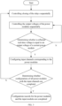
- FIG. 1 illustrates a flowchart of a configuration method for power distribution according to an embodiment of the present disclosure.
- the present specification provides a method operation step according to an embodiment or a flowchart, and may include more or fewer operation steps based on conventional or non-creative efforts.
- a sequence of the steps listed in the embodiments is merely one of a plurality of step execution sequences, and does not represent a unique execution sequence.
- a system or a server product may be executed sequentially or in parallel (e.g., a parallel processor or a multithread processing environment) based on the method sequence illustrated in the embodiments or the accompanying drawings.
- the method specifically includes operations at blocks S101 an S 102.
- closing of at least one target relay is controlled in response to a power distribution request instruction.
- the closing of the at least one target relay is configured to bring a target input channel of the power distribution into communication with a target output channel of the power distribution.
- At block S102 at least one power module is traversed until one of the at least one power module corresponding to the target input channel is determined. During the traversing, operations at blocks S 103 to S 105 are performed.
- an output voltage of a current power module is controlled.
- a real-time voltage at the target output channel is collected.
- a correspondence between the current power module and the target input channel is determined when the real-time voltage matches with the output voltage.
- the at least one target relay includes a plurality of target relays, and the plurality of target relays is arranged in a form of a matrix with N rows and M columns.
- the relays are arranged in the form of the matrix with the N rows and the M columns, aiming to fully utilize the power module to supply a voltage to a charging device and facilitate monitoring of the output voltage to confirm the input channel corresponding to the power module.
- controlling the closing of the at least one target relay in response to the power distribution instruction further includes: closing the plurality of the target relays arranged in the matrix of the N rows and the M columns. Target input channels where the plurality of target relays is located are different from each other.
- one relay when the correspondence between the power module and the target input channel is determined by the closed relay, one relay may be closed, or a plurality of relays may be closed simultaneously.
- the plurality of relays When the plurality of relays is closed, it is necessary to ensure that the plurality of relays cannot be simultaneously in one target input channel. In this way, it is possible to easily determine a correspondence between the power module and each of the input channel and the output channel. As a result, operation efficiency is improved.
- the plurality of target relays being arranged in the form of the matrix with the N rows and the M columns includes: the target relays in each of the M columns being positioned at one input channel.
- the target relays located on the one input channel are connected to N predetermined voltage monitoring devices, respectively.
- Each of the N predetermined voltage monitoring devices is configured to monitor a real-time voltage at the output channel.
- a predetermined voltage monitoring device is mounted at the output channel.
- the voltage monitoring device is configured to monitor a voltage at the output channel to be compared with a voltage output by the power module, and then determine the correspondence between the power module and each of the input channel and the output channel.
- controlling the current the output voltage of power module includes: controlling the power module to be connected in parallel with a set of power modules to voltages.
- the power module is connected in parallel with the plurality of power modules, aiming to obtain voltages required for the charging device and avoid a problem of idle power. Therefore, it is possible to facilitate providing a plurality of voltages by the charging devices with different requirements.
- the configuration method further includes, subsequent to the traversing the at least one power module until the one of the at least one power module corresponding to the target input channel is determined: determining whether configurations of all power modules with the input channel are completed; ending the configuration for the power distribution, in response to determining that the configurations of all power modules with the input channel are completed; and controlling, in response to determining that the configurations of all power modules with the input channels are not completed, closing of a next target relay, and traversing the at least one power module until one of the at least one the power module corresponding to the target input channel is determined, until the configurations of all power modules with the input channel are completed.
- operations at this step are to determine whether the configurations of all power modules with the input channel are completed.
- the configuration method further includes, when the real-time voltage mismatches with the output voltage: controlling an output voltage of a next power module; collecting the real-time voltage at the target output channel; determining whether the real-time voltage is equal to the output voltage of the next power module; determining a correspondence between the next power module and the target input channel in response to determining that the real-time voltage is equal to the output voltage of the next power module; and controlling, in response to determining that the real-time voltage is unequal to the output voltage of the next power module, the output voltage of the power module, and collecting a real-time voltage at the target output channel, until the real-time voltage value is equal to the output voltage of the power module.
- the voltage monitored by the voltage monitoring device mismatches with the voltage output by the power module, it is necessary to control the output voltage of the next power module again and then collect the voltage at the output channel until the real-time voltage value is equal to the output voltage of the power module.
- This process is constitutes performed in a cycle manner until a predetermined condition is satisfied. At this time, it is determined that the correspondence between the power module and each of the input channel and the output channel is completed.
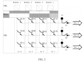
- FIG. 2 a configuration hardware control diagram for power distribution according to an embodiment of the present disclosure is illustrated.
- An individual voltage/current control and adjustment is performed on each power module by a controller (PMU) based on a power distribution request instruction, where Module 1 ⁇ x represent power modules configured to output a parameter voltage/current; Wire represents a connection line; In i represents an i-th input channel; S i-j represents i*j relays, and the i*j relays are configured to control a communicated power distribution channel in a matrix arrangement manner; and Tj represents a j-th predetermined voltage collection device; and Out j is a j-th output channel.
- PMU controller
- one function distribution module has a plurality of input channels and a plurality of output channels. Different input channels may be mapped to different output channels, and operation quality of each power module in the input channel is controlled by the PMU. During wiring and assembling, different modules may be connected to different input modules of the PDU. The PDU realizes the mapping of the relationship between the input channels and the output channels, and the PMU needs to control the power module connected to the input channel based on output requirements.
- FIG. 3 is an executing flowchart of a configuration method for power distribution according to an embodiment of the present disclosure, aiming to automatically recognize and configure the input channel and the power module. Specifically, for example, when all relays in the PDU are in an off state, one relay, e.g., S1-A illustrated in FIG. 2 , is closed. In this case, Module 1-Module X are sequentially controlled by the PMU to output a specific voltage, such as 300V, and real-time voltages are sampled at output positions TA/TB/.../Tj.
- a specific voltage such as 300V
- a power module corresponding to the S1-A is the Module 1. That is, the power module configured for an input channel In 1 of the PDU is the Module 1. Then, the S1-A is opened, S2-A is closed, and the Modules are sequentially controlled again and real-time sampling is performed at the output position Tj based on the above-mentioned method to determine a power module Module x configured for an input channel In2 of the PDU. Finally, a power module configured for each input channel of the PDU can be identified through sequential actions on all the relays.
- a charging gun corresponding to each output channel of the PDU can be identified by sampling a voltage at the sampling point Tj.
- the controller can control the output voltage of the power module and the closing of the relay, and the input channel where the closed relay is located is determined by collecting the output voltage by means of the predetermined voltage collection device, and then the power module configured for the input channel is determined.
- the configuration relationship between the input channel and the power module is automatically recognized during charging of the charging device, to reduce an on-site wiring and mounting difficulty and prevent harm due to a personnel operation error.
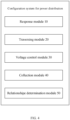
- the embodiments of the present disclosure further provide a configuration system for power distribution.
- the system includes a response module 10 and a a traversing module 20.
- the response module 10 is configured to control closing of at least one target relay in response to a power distribution request instruction, and the closing of the at least one target relay is configured to bring a target input channel of the power distribution into communication with a target output channel of the power distribution.
- the traversing module 20 is configured to traverse at least one power module until one of the at least one power module corresponding to the target input channel is determined.
- steps are performed of: a voltage control module 30 configured to control an output voltage of a current power module; a collection module 40 configured to collect a real-time voltage at the target output channel; and a relationship determination module 50 configured to determine a correspondence between the current power module and the target input channel when the real-time voltage matches with the output voltage.
- the at least one target relay includes a plurality of target relays, and the plurality of target relays is arranged in a form of a matrix with N rows and M columns.
- the response module 10 includes a relay closing module configured to close the plurality of the target relays arranged in the matrix of the N rows and the M columns.
- Target input channels where the plurality of target relays is located are different from each other.
- the plurality of target relays being arranged in the form of the matrix with the N rows and the M columns includes a relay connection module configured for the target relays in each of the M columns being positioned at one input channel.
- the target relays located on the one input channel are connected to N predetermined voltage monitoring devices, respectively.
- Each of the N predetermined voltage monitoring devices is configured to monitor a real-time voltage at the output channel.
- the configuration system includes a power module connection module configured to control the power module to be connected in parallel with a set of power modules to output voltages.
- the configuration system includes, subsequent to the traversing module 20, a determination module: configured to determine whether configurations of all power modules with the input channel are completed, end the configuration for the power distribution, in response to determining that the configuration of all power modules to the input channel is completed, and control, in response to determining that the configurations of all power modules with the input channels are not completed, closing of a next target relay, and traverse the at least one power module until one of the at least one power module corresponding to the target input channel is determined, until the configurations of all power modules with the input channel are completed.
- a determination module configured to determine whether configurations of all power modules with the input channel are completed, end the configuration for the power distribution, in response to determining that the configuration of all power modules to the input channel is completed, and control, in response to determining that the configurations of all power modules with the input channels are not completed, closing of a next target relay, and traverse the at least one power module until one of the at least one power module corresponding to the target input channel is determined, until the configurations of all power modules
- the configuration system includes: a first control module configured to control, when the real-time voltage mismatches with the output voltage, an output voltage of a next power module; a collection module configure to collect a real-time voltage at the target output channel; a first determination module configure to: determine whether the real-time voltage is equal to the output voltage of the next power module, determine a correspondence between the next power module and the target input channel in response to determining that the real-time voltage is equal to the output voltage of the next power module; and control, in response to determining that the real-time voltage is unequal to the output voltage of the next power module, the output voltage of the power module, and collect the real-time voltage at the target output channel, until the real-time voltage value is equal to the output voltage of the power module.
- Embodiments of the present disclosure provide a device.
- the device includes a processor and a memory.
- the memory has at least one instruction, at least one program, a code set, or an instruction set stored thereon.
- the at least one instruction, the at least one program, the code set, or the instruction set is loaded and executed by the processor to implement the configuration method for the power distribution according to the above-mentioned method embodiments.
- Embodiments of the present disclosure provide a storage medium.
- the storage medium may be disposed in a server to save at least one instruction, at least one program, a code set, or an instruction for implementing a data processing method in the method embodiments.
- the at least one instruction, the at least one program, the code set, or the instruction set is loaded and executed by a processor to implement the configuration method for the power distribution according to the above-mentioned method embodiments.
Landscapes
- Engineering & Computer Science (AREA)
- Power Engineering (AREA)
- Transportation (AREA)
- Mechanical Engineering (AREA)
- Supply And Distribution Of Alternating Current (AREA)
- Remote Monitoring And Control Of Power-Distribution Networks (AREA)
- Charge And Discharge Circuits For Batteries Or The Like (AREA)
Applications Claiming Priority (1)
| Application Number | Priority Date | Filing Date | Title |
|---|---|---|---|
| PCT/CN2021/085364 WO2022205439A1 (zh) | 2021-04-02 | 2021-04-02 | 一种用于功率分配的配置方法、系统、设备及存储介质 |
Publications (2)
| Publication Number | Publication Date |
|---|---|
| EP4316902A1 true EP4316902A1 (de) | 2024-02-07 |
| EP4316902A4 EP4316902A4 (de) | 2024-06-12 |
Family
ID=83455519
Family Applications (1)
| Application Number | Title | Priority Date | Filing Date |
|---|---|---|---|
| EP21934096.5A Pending EP4316902A4 (de) | 2021-04-02 | 2021-04-02 | Konfigurationsverfahren zur stromverteilung, system, vorrichtung und speichermedium |
Country Status (3)
| Country | Link |
|---|---|
| EP (1) | EP4316902A4 (de) |
| CN (1) | CN116601042B (de) |
| WO (1) | WO2022205439A1 (de) |
Families Citing this family (3)
| Publication number | Priority date | Publication date | Assignee | Title |
|---|---|---|---|---|
| CN115923565B (zh) * | 2022-12-30 | 2025-02-14 | 领充新能源科技有限公司 | 功率模块控制方法、装置及系统 |
| CN118487257A (zh) * | 2024-07-15 | 2024-08-13 | 福建时代星云科技有限公司 | 一种dcdc系统及其柔性调度方法、终端 |
| CN122034770A (zh) * | 2025-01-08 | 2026-05-15 | 领充新能源科技有限公司 | 充电系统及其通道匹配方法、充电设备 |
Family Cites Families (14)
| Publication number | Priority date | Publication date | Assignee | Title |
|---|---|---|---|---|
| NL2004746C2 (en) * | 2010-05-19 | 2011-11-22 | Epyon B V | Charging system for electric vehicles. |
| US10090777B2 (en) * | 2011-05-08 | 2018-10-02 | Koolbridge Solar, Inc. | Inverter with independent current and voltage controlled outputs |
| US9240685B2 (en) * | 2013-01-21 | 2016-01-19 | Hamilton Sundstrand Corporation | Reconfigurable matrix-based power distribution architecture |
| JP2014176232A (ja) * | 2013-03-11 | 2014-09-22 | Denso Corp | 電動車両用充電システム |
| DE102014119431A1 (de) * | 2014-12-22 | 2016-06-23 | Gip Ag | Elektrischer Leistungsverteiler und Verfahren zum Verteilen elektrischer Leistung |
| CN105375552B (zh) * | 2015-09-01 | 2017-03-15 | 西安特锐德智能充电科技有限公司 | 一种矩阵式功率分配充电系统的功率匹配方法 |
| WO2017147612A1 (en) * | 2016-02-25 | 2017-08-31 | California Institute Of Technology | Adaptive charging network using adaptive charging stations for electric vehicles |
| KR101905997B1 (ko) * | 2016-11-09 | 2018-10-08 | 현대자동차주식회사 | 차량탑재형 충전장치 |
| CN107117049B (zh) * | 2017-04-28 | 2019-12-13 | 西安特锐德智能充电科技有限公司 | 一种自识别模块位置的单桩多枪通道匹配方法 |
| US11196258B2 (en) * | 2018-08-03 | 2021-12-07 | Sacramento Municipal Utility District | Energy control and storage system for controlling power based on a load shape |
| CN109455106B (zh) * | 2018-10-17 | 2022-07-26 | 国网浙江省电力有限公司杭州供电公司 | 一种电动汽车智能充电站 |
| CN109484224B (zh) * | 2018-12-07 | 2024-08-02 | 广州南方电力集团科技发展有限公司 | 一种具备功率柔性分配功能的电动汽车充电装置 |
| CN111347900B (zh) * | 2018-12-21 | 2021-11-12 | 比亚迪股份有限公司 | 一种车辆、电机控制电路、动力电池充电与加热方法 |
| CN209454588U (zh) * | 2019-01-30 | 2019-10-01 | 青岛海汇德电气有限公司 | 充电设备及系统 |
-
2021
- 2021-04-02 EP EP21934096.5A patent/EP4316902A4/de active Pending
- 2021-04-02 WO PCT/CN2021/085364 patent/WO2022205439A1/zh not_active Ceased
- 2021-04-02 CN CN202180083676.XA patent/CN116601042B/zh active Active
Also Published As
| Publication number | Publication date |
|---|---|
| CN116601042A (zh) | 2023-08-15 |
| WO2022205439A1 (zh) | 2022-10-06 |
| EP4316902A4 (de) | 2024-06-12 |
| CN116601042B (zh) | 2025-09-23 |
Similar Documents
| Publication | Publication Date | Title |
|---|---|---|
| CN116601042B (zh) | 一种用于功率分配的配置方法、系统、设备及存储介质 | |
| US20180157483A1 (en) | Integrated management and update method of dc-dc converter and battery management system (bms) software installed in residential ess | |
| CN104898633A (zh) | 一种核电厂非安全级dcs组态测试方法及系统 | |
| CN109066745B (zh) | 电储能系统及其运行控制方法、装置、系统 | |
| US20220308567A1 (en) | System and method for controlling non-product wafer, storage medium and electronic device | |
| CN110727255A (zh) | 一种整车控制器软件升级测试系统及车辆 | |
| US20080052560A1 (en) | Field bus communication diagnosing device and field bus communication diagnosing method | |
| CN116119019A (zh) | 一种飞行参数采集记录设备测试系统及测试方法 | |
| CN202339497U (zh) | 一种星载综合业务单元验证系统 | |
| CN112213633A (zh) | 一种换相开关寿命试验自动测试装置及其测试方法 | |
| CN110824279A (zh) | 继电保护装置自动测试系统和方法 | |
| CN111193968A (zh) | 遥信信息的验证方法、调试验证主机、监控主机和系统 | |
| CN103163407A (zh) | 一种测试系统中多个测试通道的转换方法 | |
| CN112910024B (zh) | 充电桩中功率模块位置的确定方法、装置和充电桩 | |
| US20240170975A1 (en) | Method, system, device and medium for recharging battery module | |
| CN119104907A (zh) | 针对锂离子电池的测试系统 | |
| AU2006337975B2 (en) | Method for storing a data block containing data for controlling a technical process, and control and automation apparatus | |
| CN114655069B (zh) | 一种动力电池控制方法、装置、电池管理系统及电动汽车 | |
| CN210924277U (zh) | 一种集成多种hil系统的氢能汽车测试装置 | |
| JP2019158397A (ja) | 蓄電池システム | |
| CN113703421A (zh) | 一种汽车充电口盖控制测试设备的测试设备及方法 | |
| CN117196082A (zh) | 电池产线的产能预测方法及装置和存储介质 | |
| CN112583680B (zh) | 一种电池管理系统及其从机地址自动标定方法 | |
| CN111431285A (zh) | 一种直流电源监控系统及方法 | |
| KR102534217B1 (ko) | 에너지 저장 시스템의 통신 아이디 설정 장치 |
Legal Events
| Date | Code | Title | Description |
|---|---|---|---|
| STAA | Information on the status of an ep patent application or granted ep patent |
Free format text: STATUS: THE INTERNATIONAL PUBLICATION HAS BEEN MADE |
|
| PUAI | Public reference made under article 153(3) epc to a published international application that has entered the european phase |
Free format text: ORIGINAL CODE: 0009012 |
|
| STAA | Information on the status of an ep patent application or granted ep patent |
Free format text: STATUS: REQUEST FOR EXAMINATION WAS MADE |
|
| 17P | Request for examination filed |
Effective date: 20231031 |
|
| AK | Designated contracting states |
Kind code of ref document: A1 Designated state(s): AL AT BE BG CH CY CZ DE DK EE ES FI FR GB GR HR HU IE IS IT LI LT LU LV MC MK MT NL NO PL PT RO RS SE SI SK SM TR |
|
| A4 | Supplementary search report drawn up and despatched |
Effective date: 20240514 |
|
| RIC1 | Information provided on ipc code assigned before grant |
Ipc: B60L 53/62 20190101ALI20240507BHEP Ipc: H02J 3/00 20060101ALI20240507BHEP Ipc: B60L 53/20 20190101ALI20240507BHEP Ipc: B60L 53/30 20190101AFI20240507BHEP |
|
| DAV | Request for validation of the european patent (deleted) | ||
| DAX | Request for extension of the european patent (deleted) |