EP4316936B1 - Procédé de fonctionnement d'un système d'assistance au conducteur pour un procédé de changement de voie assisté d'un véhicule automobile - Google Patents
Procédé de fonctionnement d'un système d'assistance au conducteur pour un procédé de changement de voie assisté d'un véhicule automobile Download PDFInfo
- Publication number
- EP4316936B1 EP4316936B1 EP23186100.6A EP23186100A EP4316936B1 EP 4316936 B1 EP4316936 B1 EP 4316936B1 EP 23186100 A EP23186100 A EP 23186100A EP 4316936 B1 EP4316936 B1 EP 4316936B1
- Authority
- EP
- European Patent Office
- Prior art keywords
- lane
- lane change
- data
- vehicle
- motor vehicle
- Prior art date
- Legal status (The legal status is an assumption and is not a legal conclusion. Google has not performed a legal analysis and makes no representation as to the accuracy of the status listed.)
- Active
Links
Images

Classifications
-
- B—PERFORMING OPERATIONS; TRANSPORTING
- B60—VEHICLES IN GENERAL
- B60W—CONJOINT CONTROL OF VEHICLE SUB-UNITS OF DIFFERENT TYPE OR DIFFERENT FUNCTION; CONTROL SYSTEMS SPECIALLY ADAPTED FOR HYBRID VEHICLES; ROAD VEHICLE DRIVE CONTROL SYSTEMS FOR PURPOSES NOT RELATED TO THE CONTROL OF A PARTICULAR SUB-UNIT
- B60W30/00—Purposes of road vehicle drive control systems not related to the control of a particular sub-unit, e.g. of systems using conjoint control of vehicle sub-units
- B60W30/18—Propelling the vehicle
- B60W30/18009—Propelling the vehicle related to particular drive situations
- B60W30/18163—Lane change; Overtaking manoeuvres
-
- B—PERFORMING OPERATIONS; TRANSPORTING
- B60—VEHICLES IN GENERAL
- B60W—CONJOINT CONTROL OF VEHICLE SUB-UNITS OF DIFFERENT TYPE OR DIFFERENT FUNCTION; CONTROL SYSTEMS SPECIALLY ADAPTED FOR HYBRID VEHICLES; ROAD VEHICLE DRIVE CONTROL SYSTEMS FOR PURPOSES NOT RELATED TO THE CONTROL OF A PARTICULAR SUB-UNIT
- B60W30/00—Purposes of road vehicle drive control systems not related to the control of a particular sub-unit, e.g. of systems using conjoint control of vehicle sub-units
- B60W30/08—Active safety systems predicting or avoiding probable or impending collision or attempting to minimise its consequences
- B60W30/095—Predicting travel path or likelihood of collision
- B60W30/0956—Predicting travel path or likelihood of collision the prediction being responsive to traffic or environmental parameters
-
- B—PERFORMING OPERATIONS; TRANSPORTING
- B60—VEHICLES IN GENERAL
- B60W—CONJOINT CONTROL OF VEHICLE SUB-UNITS OF DIFFERENT TYPE OR DIFFERENT FUNCTION; CONTROL SYSTEMS SPECIALLY ADAPTED FOR HYBRID VEHICLES; ROAD VEHICLE DRIVE CONTROL SYSTEMS FOR PURPOSES NOT RELATED TO THE CONTROL OF A PARTICULAR SUB-UNIT
- B60W40/00—Estimation or calculation of non-directly measurable driving parameters for road vehicle drive control systems not related to the control of a particular sub unit, e.g. by using mathematical models
- B60W40/02—Estimation or calculation of non-directly measurable driving parameters for road vehicle drive control systems not related to the control of a particular sub unit, e.g. by using mathematical models related to ambient conditions
-
- B—PERFORMING OPERATIONS; TRANSPORTING
- B60—VEHICLES IN GENERAL
- B60W—CONJOINT CONTROL OF VEHICLE SUB-UNITS OF DIFFERENT TYPE OR DIFFERENT FUNCTION; CONTROL SYSTEMS SPECIALLY ADAPTED FOR HYBRID VEHICLES; ROAD VEHICLE DRIVE CONTROL SYSTEMS FOR PURPOSES NOT RELATED TO THE CONTROL OF A PARTICULAR SUB-UNIT
- B60W50/00—Details of control systems for road vehicle drive control not related to the control of a particular sub-unit, e.g. process diagnostic or vehicle driver interfaces
- B60W50/06—Improving the dynamic response of the control system, e.g. improving the speed of regulation or avoiding hunting or overshoot
-
- G—PHYSICS
- G01—MEASURING; TESTING
- G01S—RADIO DIRECTION-FINDING; RADIO NAVIGATION; DETERMINING DISTANCE OR VELOCITY BY USE OF RADIO WAVES; LOCATING OR PRESENCE-DETECTING BY USE OF THE REFLECTION OR RERADIATION OF RADIO WAVES; ANALOGOUS ARRANGEMENTS USING OTHER WAVES
- G01S15/00—Systems using the reflection or reradiation of acoustic waves, e.g. sonar systems
- G01S15/88—Sonar systems specially adapted for specific applications
- G01S15/93—Sonar systems specially adapted for specific applications for anti-collision purposes
- G01S15/931—Sonar systems specially adapted for specific applications for anti-collision purposes of land vehicles
-
- G—PHYSICS
- G01—MEASURING; TESTING
- G01S—RADIO DIRECTION-FINDING; RADIO NAVIGATION; DETERMINING DISTANCE OR VELOCITY BY USE OF RADIO WAVES; LOCATING OR PRESENCE-DETECTING BY USE OF THE REFLECTION OR RERADIATION OF RADIO WAVES; ANALOGOUS ARRANGEMENTS USING OTHER WAVES
- G01S7/00—Details of systems according to groups G01S13/00, G01S15/00, G01S17/00
- G01S7/52—Details of systems according to groups G01S13/00, G01S15/00, G01S17/00 of systems according to group G01S15/00
- G01S7/523—Details of pulse systems
- G01S7/526—Receivers
- G01S7/53—Means for transforming coordinates or for evaluating data, e.g. using computers
-
- B—PERFORMING OPERATIONS; TRANSPORTING
- B60—VEHICLES IN GENERAL
- B60W—CONJOINT CONTROL OF VEHICLE SUB-UNITS OF DIFFERENT TYPE OR DIFFERENT FUNCTION; CONTROL SYSTEMS SPECIALLY ADAPTED FOR HYBRID VEHICLES; ROAD VEHICLE DRIVE CONTROL SYSTEMS FOR PURPOSES NOT RELATED TO THE CONTROL OF A PARTICULAR SUB-UNIT
- B60W2420/00—Indexing codes relating to the type of sensors based on the principle of their operation
- B60W2420/54—Audio sensitive means, e.g. ultrasound
-
- B—PERFORMING OPERATIONS; TRANSPORTING
- B60—VEHICLES IN GENERAL
- B60W—CONJOINT CONTROL OF VEHICLE SUB-UNITS OF DIFFERENT TYPE OR DIFFERENT FUNCTION; CONTROL SYSTEMS SPECIALLY ADAPTED FOR HYBRID VEHICLES; ROAD VEHICLE DRIVE CONTROL SYSTEMS FOR PURPOSES NOT RELATED TO THE CONTROL OF A PARTICULAR SUB-UNIT
- B60W2540/00—Input parameters relating to occupants
- B60W2540/20—Direction indicator values
-
- B—PERFORMING OPERATIONS; TRANSPORTING
- B60—VEHICLES IN GENERAL
- B60W—CONJOINT CONTROL OF VEHICLE SUB-UNITS OF DIFFERENT TYPE OR DIFFERENT FUNCTION; CONTROL SYSTEMS SPECIALLY ADAPTED FOR HYBRID VEHICLES; ROAD VEHICLE DRIVE CONTROL SYSTEMS FOR PURPOSES NOT RELATED TO THE CONTROL OF A PARTICULAR SUB-UNIT
- B60W2552/00—Input parameters relating to infrastructure
- B60W2552/10—Number of lanes
-
- B—PERFORMING OPERATIONS; TRANSPORTING
- B60—VEHICLES IN GENERAL
- B60W—CONJOINT CONTROL OF VEHICLE SUB-UNITS OF DIFFERENT TYPE OR DIFFERENT FUNCTION; CONTROL SYSTEMS SPECIALLY ADAPTED FOR HYBRID VEHICLES; ROAD VEHICLE DRIVE CONTROL SYSTEMS FOR PURPOSES NOT RELATED TO THE CONTROL OF A PARTICULAR SUB-UNIT
- B60W2552/00—Input parameters relating to infrastructure
- B60W2552/53—Road markings, e.g. lane marker or crosswalk
-
- B—PERFORMING OPERATIONS; TRANSPORTING
- B60—VEHICLES IN GENERAL
- B60W—CONJOINT CONTROL OF VEHICLE SUB-UNITS OF DIFFERENT TYPE OR DIFFERENT FUNCTION; CONTROL SYSTEMS SPECIALLY ADAPTED FOR HYBRID VEHICLES; ROAD VEHICLE DRIVE CONTROL SYSTEMS FOR PURPOSES NOT RELATED TO THE CONTROL OF A PARTICULAR SUB-UNIT
- B60W2554/00—Input parameters relating to objects
- B60W2554/40—Dynamic objects, e.g. animals, windblown objects
- B60W2554/404—Characteristics
- B60W2554/4045—Intention, e.g. lane change or imminent movement
-
- B—PERFORMING OPERATIONS; TRANSPORTING
- B60—VEHICLES IN GENERAL
- B60W—CONJOINT CONTROL OF VEHICLE SUB-UNITS OF DIFFERENT TYPE OR DIFFERENT FUNCTION; CONTROL SYSTEMS SPECIALLY ADAPTED FOR HYBRID VEHICLES; ROAD VEHICLE DRIVE CONTROL SYSTEMS FOR PURPOSES NOT RELATED TO THE CONTROL OF A PARTICULAR SUB-UNIT
- B60W2556/00—Input parameters relating to data
- B60W2556/05—Big data
-
- B—PERFORMING OPERATIONS; TRANSPORTING
- B60—VEHICLES IN GENERAL
- B60W—CONJOINT CONTROL OF VEHICLE SUB-UNITS OF DIFFERENT TYPE OR DIFFERENT FUNCTION; CONTROL SYSTEMS SPECIALLY ADAPTED FOR HYBRID VEHICLES; ROAD VEHICLE DRIVE CONTROL SYSTEMS FOR PURPOSES NOT RELATED TO THE CONTROL OF A PARTICULAR SUB-UNIT
- B60W2556/00—Input parameters relating to data
- B60W2556/40—High definition maps
-
- B—PERFORMING OPERATIONS; TRANSPORTING
- B60—VEHICLES IN GENERAL
- B60W—CONJOINT CONTROL OF VEHICLE SUB-UNITS OF DIFFERENT TYPE OR DIFFERENT FUNCTION; CONTROL SYSTEMS SPECIALLY ADAPTED FOR HYBRID VEHICLES; ROAD VEHICLE DRIVE CONTROL SYSTEMS FOR PURPOSES NOT RELATED TO THE CONTROL OF A PARTICULAR SUB-UNIT
- B60W2556/00—Input parameters relating to data
- B60W2556/45—External transmission of data to or from the vehicle
- B60W2556/50—External transmission of data to or from the vehicle of positioning data, e.g. GPS [Global Positioning System] data
Definitions
- the invention relates to a method for operating a driver assistance system for an assisted lane change of a motor vehicle from an initial lane to an adjacent target lane, having at least one environmental sensor for detecting objects in an environment of the motor vehicle, and at least one map unit for detecting map data about the lane course.
- the invention further relates to a driver assistance system and a motor vehicle as well as software for carrying out the method.
- driver assistance systems that support the driver when driving the vehicle.
- driver assistance systems record and evaluate the vehicle's surroundings in particular in order to detect dangerous situations, especially collision risks, at an early stage and to support the driver in his driving maneuvers or to avoid them completely.
- a driver assistance system is understood here and below to mean in particular a device of a motor vehicle which supports the driver when driving the motor vehicle.
- driver assistance systems can be designed both as pure information systems which show the driver supporting information (e.g. direction arrows on a display) and as driving systems which automatically influence the movement of the motor vehicle (e.g. steering and/or acceleration).
- a lane change assistance system is a driver assistance system that supports or assists the driver when changing lanes.
- a lane change procedure also known as a lane change procedure, is understood here and below to mean a lane change (lane change, roadway change) of the motor vehicle from an exit lane (ego lane) to an adjacent target lane (neighboring lane) on a roadway with at least two lanes.
- the lanes of the roadway are usually bordered on both sides by road lines or stripes (guide lines, lane markings, roadway markings, etc.).
- the exit lane and the target lane are separated from one another by a road line, which is crossed or crossed by the motor vehicle during the lane change procedure.
- US 2018/086338 A1 discloses a method for operating a driver assistance system for an assisted lane change of a motor vehicle from an exit lane to an adjacent target lane, comprising at least one environmental sensor for detecting objects in an environment of the motor vehicle, and at least one map unit for detecting map data about the lane course.
- the lane change process is started, for example, by triggering or activating the vehicle's indicator.
- the vehicle is then moved in the direction of the road line between the starting lane and the target lane.
- the so-called lane change maneuver takes place, in which the vehicle leaves the starting lane, crosses the road line and moves completely into the target lane.
- the vehicle is steered so that it essentially moves along the target lane.
- the vehicle's indicator is automatically deactivated, for example, and the lane change process ends.
- lane change assistance systems can only be activated when the vehicle speed reaches a specified minimum (e.g. 90 km/h), with vehicle sensors monitoring the vehicle's surroundings. A lane change is only assisted if it can be carried out safely. If the lane change assistance system is activated, the lane change can be started and carried out by, for example, flicking the indicator (comfort indicator). The prerequisite is that the vehicle sensors have not detected any objects in a safety-critical area.
- a capacitive touch sensor is used, for example, to monitor that the driver's hands are on the steering wheel. The vehicle then steers itself into the desired (driving) lane. However, the driver can intervene at any time and take over the maneuver.
- both a vehicle camera and radar and ultrasonic sensors are used as driving sensors to monitor the vehicle's surroundings. As soon as the ultrasonic sensors detect an object in the target lane of the lane change in a safety-critical area, the lane change is aborted or the lane change authorization is withdrawn.
- the ultrasonic sensors in particular are designed as near-field sensors, which are generally designed to assist with parking maneuvers. This means that the ultrasonic sensors are designed or configured to be particularly sensitive to low vehicle speeds. Due to this sensitivity setting, at higher vehicle speeds the ultrasonic sensors may detect phantom objects or interfering objects that are not critical for the lane change process but can lead to an increased number of implausible lane change aborts.
- Another possibility is to ignore the ultrasonic objects detected during the lane change as soon as the vehicle is in the target lane during the lane change maneuver.
- this can lead to safety-critical problems, for example when changing lanes on a three-lane road from the right lane to the middle lane. If in this scenario another vehicle from the left lane also drives into the target lane, the lane change would no longer be aborted because the ultrasonic objects are not evaluated or taken into account for this period of time (a few seconds).
- the invention is based on the object of specifying a particularly suitable method for operating a driver assistance system for an assisted lane change of a motor vehicle from an initial lane to an adjacent target lane.
- data from an environmental sensor should be evaluated during the lane change process without causing a general negative influence on the function.
- the invention is also based on the object of specifying a particularly suitable driver assistance system and a particularly suitable motor vehicle as well as particularly suitable software on a data carrier.
- the object is achieved according to the invention with the features of claim 1 and with regard to the driver assistance system with the features of claim 10, as well as with regard to the motor vehicle with the features of claim 11 and with regard to the software with the features of claim 12.
- Advantageous embodiments and further developments are the subject of the subclaims.
- the advantages and embodiments cited with regard to the method can also be transferred mutatis mutandis to the driver assistance system and/or the motor vehicle and/or the software and vice versa.
- the method according to the invention is intended for operating a driver assistance system, in particular a lane change assistance system, of a motor vehicle and is suitable and designed for this purpose.
- the method is designed in particular for carrying out an assisted lane change process (lane change procedure) on a multi-lane, in particular at least two-lane, roadway from an initial lane (ego lane) to an adjacent target lane (neighboring lane).
- the driver assistance system has at least one environmental sensor for detecting objects in the environment of the motor vehicle.
- An environmental sensor is to be understood in particular as a non-optical near-field sensor, preferably an ultrasonic sensor.
- the driver assistance system also has at least one map unit for detecting map data about the lane course of the roadway. Map data is therefore understood in particular as (driving) lane data.
- a current vehicle position is determined based on the map data.
- a position is determined in the map data that essentially corresponds to the vehicle position of the motor vehicle on the road.
- a vehicle user can activate or initiate a lane change process, for example by activating a vehicle indicator, in particular by flicking, if a vehicle speed is greater than a stored minimum speed (for example greater than 90 km/h).
- a lane change distance for the lane change process is first predicted or estimated.
- the lane change distance is the distance that the motor vehicle is expected to travel during the lane change process.
- the lane change distance is therefore the distance that the motor vehicle is expected to travel between the activation and deactivation of the vehicle's indicator.
- the lane change distance corresponds to the predicted course of the vehicle's position.
- forward-looking estimate i.e. a prediction, in which a future or expected vehicle route is calculated or predicted based on a current and/or past vehicle state (vehicle position, vehicle speed, ...) - possibly with the addition of mathematical or physical models - which occurs with a sufficient probability. What probability is considered sufficient and how large the probability actually is is initially irrelevant. This leaves can be determined, for example, from past driving data or from corresponding tests or trials. Different predicted lane change distances may result for different motor vehicles, operating and environmental conditions (time of day, weather, weather conditions, etc.) or application scenarios.
- a probability measure for a lane change of another road user, in particular another motor vehicle, into the target lane is then determined for the predicted lane change distance.
- the probability measure is therefore a measure of the probability that another road user will change into the target lane during the lane change process.
- a risk of collision with another road user during the lane change process is essentially determined. It is therefore determined how high the probability is that an object relevant to the lane change process can be detected by the environmental sensor.
- the probability measure is estimated or predicted, for example.
- a sensitivity of the environmental sensor for detecting objects is set depending on the probability measure. For example, the sensitivity is reduced if the probability measure is low and the sensitivity is increased if the probability measure is high.
- the probability measure is assessed, for example, using a suitable threshold comparison.
- the "(sensor) sensitivity" of the environmental sensor is understood here and below to mean in particular the response capability or the triggering behavior, i.e. for example the (sensor) sensitivity.
- the sensitivity characterizes, for example, a (response) threshold in the evaluation of the environmental sensor, from which a sensor signal is classified as a (disturbing) object or not.
- the environment is continuously monitored by the environmental sensor during the lane change process, i.e. when driving along the lane change route, and the lane change process is aborted if an object is detected by the environmental sensor.
- the environmental sensor is evaluated during the entire lane change procedure, i.e. both in the starting lane and in the target lane.
- the probability-dependent setting of the sensor sensitivity improves the robustness of an assisted lane change by adapting the sensor sensitivity to the respective situation. This reduces the number of incorrectly detected phantom or interfering objects, so that the lane change process is aborted implausibly less often.
- navigation data from an in-vehicle navigation device and/or swarm data (fleet data) from a data cloud are used as map data.
- the map unit thus comprises, for example, the navigation device and/or a receiving device for the swarm data.
- the swarm data is map or lane data that is generated by multiple sources (the swarm).
- the swarm data is created in particular via crowdsourcing by a large number of motor vehicles (fleet/swarm vehicles).
- the motor vehicles involved in the swarm use optical sensor systems to record lane markings and/or road information, which is then compressed and sent to the data cloud.
- the use of swarm data essentially enables real-time updating of the lane data provided, so that the process can be dynamically and flexibly adapted to different situations (construction sites, etc.) even while driving.
- the probability measure is determined using the map data.
- the map data is evaluated for features that are relevant to the probability measure, and then the probability measure is determined from the recorded features. This enables a practical and reliable determination of the probability measure.
- an impending lane reduction is used as a feature.
- the map data is examined to determine the probability measure for a lane reduction (roadway reduction).
- a lane reduction is understood here in particular to mean a merging or combining of two adjacent lanes into a single lane.
- the map data is examined here for lane reductions in which the lanes are combined or merged to or with the target lane.
- the map data is examined for lane reductions in which a lane adjacent to the target lane, which is not the starting lane, is combined or merged with the target lane. This enables a particularly advantageous determination of the probability measure, since in the area of such lane reductions the probability is particularly high that another motor vehicle will change to the target lane during the lane change process.
- a lane reduction is identified, determined or localized in particular using the swarm data.
- the swarm data includes, for example, route data of the swarm vehicles, which correspond to the paths driven by the swarm vehicles (drivable path).
- the route data therefore correspond to the average or average route on the road. If two such routes cross or intersect at an intersection and then continue essentially as one route, this is a reliable indicator of the presence of a lane reduction.
- a position area localized around the intersection is used for the comparison with the lane change route. During the process, it is therefore checked whether the position area overlaps with the lane change route. If so, there is an increased degree of probability.
- the position range is limited by a lower limit and an upper limit.
- the lower limit is determined by a difference between the intersection point and a stored lower threshold value
- the upper limit is determined by a sum of the intersection point and a stored upper threshold value.
- the stored threshold values are specified, for example, based on legal regulations or on pre-characterized measurements and stored in a memory.
- the threshold values are therefore preferably not changed during the process and are therefore identical for each assisted lane change process.
- the threshold values can also be adjusted, for example, by updating the sensor hardware and/or sensor software.
- An additional or further aspect of the invention provides that the sensitivity of the environmental sensor is changed in addition to the probability measure also depending on a (current) driving situation.
- a driving situation is understood here as a situation that characterizes the journey of the motor vehicle, which is dependent, for example, on the vehicle state of the motor vehicle (e.g. vehicle speed, torque/acceleration, ...) and/or the road surface condition (e.g. wet, frozen, potholes, ...) and/or an environmental state of the vehicle environment (e.g. weather conditions, time of day, ). This improves the operational reliability of the method.
- weather data and/or a vehicle speed of the motor vehicle are evaluated to characterize the driving situation.
- the vehicle speed and the weather conditions are relevant variables that influence the occurrence of phantom objects. For example, unwanted reflections of the ultrasonic signals occur more frequently when it is snowing, which as phantom objects. This means that the sensitivity of the ultrasonic sensors can be reduced during snowfall, for example, in order to reduce the number of implausible lane change aborts.
- the map data for determining the current vehicle position is compared with the data from a vehicle camera. This significantly improves the positioning accuracy when determining the vehicle position, enabling a particularly safe and reliable lane change process.
- the initial location is determined using a GPS position (GPS: Global Positioning System) in the map data.
- GPS position has a position inaccuracy of, for example, 2 m (meters) to 15 m.
- the vehicle camera records landmarks in the vehicle's surroundings, so-called live features, such as signs, traffic lights, lane lines, etc. The recorded landmarks are compared with corresponding stored landmarks in the map data, and an identical spatial constellation is determined in the map data. This enables fine localization with regard to position and orientation in the global coordinate system of the map data with a particularly high position accuracy in the centimeter range.
- the driver assistance system is intended for an assisted lane change process of a motor vehicle from an initial lane to an adjacent target lane and is suitable and set up for this purpose.
- the driver assistance system is thus designed in particular as a lane change assistance system.
- the driver assistance system has at least one environmental sensor for detecting objects in an environment of the motor vehicle and at least one map unit for detecting map data about the lane course of the road (lane data).
- the map unit and the environmental sensor are coupled to a controller (i.e. a control unit).
- the controller is generally set up - in terms of programming and/or circuitry - to carry out the method according to the invention described above.
- the controller is thus specifically set up to use the map data to determine a current vehicle position, to predict a lane change route for a lane change process, to determine a probability measure, to set the sensitivity of the environmental sensor depending on the probability measure, to evaluate the sensor data of the environmental sensor, and to abort the lane change process if an object is detected in the sensor data.
- the controller is at least essentially formed by a microcontroller with a processor and a data memory in which the functionality for carrying out the method according to the invention is implemented in the form of operating software (firmware) so that the method - possibly in interaction with a device user - is carried out automatically when the operating software is executed in the microcontroller.
- the controller can alternatively also be formed by a non-programmable electronic component, such as an application-specific integrated circuit (ASIC) or by an FPGA (Field Programmable Gate Array), in which the functionality for carrying out the method according to the invention is implemented using circuitry.
- ASIC application-specific integrated circuit
- FPGA Field Programmable Gate Array
- the motor vehicle according to the invention has a driver assistance system as described above. This creates a particularly suitable motor vehicle.
- An additional or further aspect of the invention provides software, i.e. a computer program product, on a medium or data carrier for carrying out or executing the method described above.
- the software is stored on a data carrier and is intended for carrying out the method described above and is suitable and designed for this purpose.
- the software is therefore in particular operating software (firmware), with the data carrier being, for example, a data memory of the controller.
- the Fig. 1 shows schematically a motor vehicle 2 with a driver assistance system 4.
- the driver assistance system 4 has a vehicle sensor system by means of which the environment of the motor vehicle 2 is monitored.
- the vehicle camera 14 is designed as a multifunctional camera with an integrated controller 20.
- the vehicle camera 14 or the controller 20 is coupled to a map unit 22.
- the map unit 22 records map data 24 about the lane course of a road and sends it to the controller 20.
- Map data 24 is understood here to mean (driving) lane data in particular.
- the map unit 22 has a server 26 (In Car Application Server, ICAS), which is coupled, for example, to a navigation device or a navigation system of the motor vehicle 2.
- the server 26 is also coupled to a transmitting and receiving unit (Online Connectivity Unit, OCU) 28, by means of which swarm data (fleet data) can be received from a data cloud.
- the map data 24 are thus, for example, navigation data 24a ( Fig. 4 ) of the navigation system and/or the swarm data 24b received from the data cloud ( Fig. 4 ).
- the swarm data 24b can be, for example, a so-called roadbook from Mobileye.
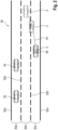
- Lane 30a is the lane oriented to the left in the direction of travel
- lane 30c is the lane oriented to the right in the direction of travel
- lane 30b is the middle lane.
- Lanes 30a, 30b, 30c are laterally delimited by road lines 32a, 32b.
- the outermost road lines 32a are designed as roadway boundaries and limit the lanes 30a and 30c to the respective road edge, with the two middle road lines 32b being designed as guide lines between the lanes 30a and 30b or 30b and 30c.
- Two road users 34 in the form of motor vehicles are shown on the lane 30a. In the Fig. 2 the motor vehicle 2 is shown at the beginning and end of a lane change maneuver from lane 30c to lane 30b as well as during the lane change maneuver when crossing the guide line 32b.
- a current vehicle position 36 on the roadway 30 is determined based on the map data 24.
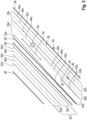
- the Fig. 3 shows, for example, map data 24 of a motorway with two lanes 30, 30 ⁇ .
- the reference symbols for the lane 30' in the opposite direction correspond to those for the lane 30, whereby the reference symbols for the lane 30' are marked with a dash ( ⁇ ).
- the lanes 30, 30' are limited by boundaries 38, 38' of the shoulders, for example by means of crash barriers.
- the lane 30' has two lanes, whereby the lane 30 in the area shown is Fig. 3 has a lane limitation from three lanes to two lanes, in which the lanes 30a and 30b are combined to form one lane 30d.
- the map data 24 are compared with the data from the vehicle camera 14 to determine the current vehicle position 36 in order to achieve increased positioning accuracy.
- live features such as signs 40, are recorded by the vehicle camera 14 and compared with the map data 24, i.e. the navigation data 24a and/or the swarm data 24b, for fine localization.
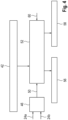
- the following is based on the Figures 4 a method for operating the driver assistance system 4 for an assisted lane change of the motor vehicle 2 from the lane 30c to the lane 30d in the area of the lane reduction is explained in more detail.
- the lane 30c on which the lane change process begins is also referred to below as the starting lane 30c, with the lane 30d on which the lane change process ends being referred to accordingly as the target lane 30d.
- the method is carried out in particular by the controller 22.
- a vehicle user (driver) of the motor vehicle 2 starts the lane change process, for example by activating a vehicle indicator, in particular by means of a touch indicator.
- a lane change distance 44 ( Fig. 2 ), i.e. a course of the vehicle position 36 for the lane change process, predicted or estimated.
- the predicted lane change distance 44 is then used to determine a probability measure for a lane change of another road user 34 to the target lane 30d.
- the probability measure is determined based on the map data 24.
- the presence of a lane reduction is used as a probability measure in particular.
- the map data 24, i.e. the navigation data 24a and the swarm data 24b are evaluated to determine whether a lane reduction is present along the lane change section 44. For example, it is checked whether the lanes 30a, 30b are combined to form the lane 30d in the interval of the lane change section 44.
- the swarm data 24b are evaluated in a method step 46.
- the swarm data include route data 48a, 48b, 48c, 48d of the swarm vehicles involved, which correspond to the (mean or average) paths driven by the swarm vehicles (drivable path) on the roadway 30.
- the route data 48a corresponds to the mean path for the lane 30a, the route data 48b to the path for the lane 30b, the route data 48c to the path for the lane 30c, and the route data 48d to the path for the lane 30d.
- the route data 48a and 48b meet at an intersection point 50 and continue from there as route data 48d.
- the intersection point 50 is thus an indicator for a lane reduction.
- the position of the intersection point 50 is used as a probability measure in a method step 52. For this purpose, it is checked whether the intersection point 50 is located in the area of the lane change path 44. To take fluctuations and deviations into account, a position area 54 located around the intersection point 50 is determined and it is checked whether the lane change path 44 overlaps with the position area 54. In other words, in the method step 52 it is checked whether the (current or future) vehicle position 36 is located in the position area 54.
- the position range 54 is limited by a lower limit (rearmost point in the direction of travel) and an upper limit (frontmost point in the direction of travel).
- the lower limit is determined by a difference of the intersection point 50 with a stored lower threshold value
- the upper limit is determined by a sum of the intersection point 50 with a stored upper threshold value.
- the sensitivity of the environmental sensors 18 is set to a comparatively high sensitivity value, and the ultrasonic sensors are evaluated during the entire lane change procedure, i.e. both in the starting lane and in the target lane.
- the sensitivity of the environmental sensors 18 is set to a comparatively low sensitivity value and the ultrasonic sensors are evaluated during the entire lane change procedure, i.e. both in the starting lane and in the target lane.
- the environmental sensors 18 detect an object during process steps 56 or 58, the lane change process is aborted.
- the method step 52 thus implements a risk-dependent sensitivity setting of the environmental sensors 18. If there is a high degree of probability that other road users 34 will also turn into the target lane, this corresponds to an increased risk of collision or accident, in which case the environmental sensors 18 are operated with a comparatively high sensitivity and, if necessary, implausible lane change aborts are accepted. If there is a low degree of probability, this corresponds to a reduced risk of collision or accident, so that in this case the environmental sensors 18 are operated with a comparatively low sensitivity, so that implausible lane change aborts are avoided or at least reduced.
- the sensitivities of the environmental sensors 18 are also changed or adjusted depending on a (current) driving situation 60 in addition to the probability measure.
- the sensitivity is set based on the current vehicle speed and/or current weather data.
Landscapes
- Engineering & Computer Science (AREA)
- Automation & Control Theory (AREA)
- Transportation (AREA)
- Mechanical Engineering (AREA)
- Radar, Positioning & Navigation (AREA)
- Physics & Mathematics (AREA)
- Remote Sensing (AREA)
- Computer Networks & Wireless Communication (AREA)
- General Physics & Mathematics (AREA)
- Acoustics & Sound (AREA)
- Human Computer Interaction (AREA)
- Mathematical Physics (AREA)
- Traffic Control Systems (AREA)
Claims (12)
- Procédé de fonctionnement d'un système d'assistance au conducteur (4) pour un processus de changement de voie assisté d'un véhicule automobile (2) d'une voie de départ (30c) à une voie cible (30d) voisine, présentant au moins un capteur d'environnement (18) pour détecter des objets dans un environnement du véhicule automobile (2), et au moins une unité cartographique (22) pour détecter des données cartographiques (24) sur le tracé de voie de circulation,- dans lequel une position de véhicule (36) actuelle est déterminée à l'aide des données cartographiques (24),- dans lequel un trajet de changement de voie (44) est prédit pour une opération de changement de voie lorsqu'une opération de changement de voie est activée,- dans lequel une mesure de probabilité pour un changement de voie d'un autre usager de la route (34) vers la voie cible (30d) est déterminée pour le trajet de changement de voie (44),- dans lequel une sensibilité du capteur d'environnement (18) pour la reconnaissance d'objets est réglée en fonction de la mesure de probabilité,- dans lequel l'environnement est surveillé en continu par le capteur d'environnement (18) pour détecter la présence d'objets pendant le processus de changement de voie, et- dans lequel l'opération de changement de voie est interrompue lorsqu'un objet est détecté par le capteur d'environnement (18).
- Procédé selon la revendication 1,
caractérisé en ce
que des données de navigation (24a) d'un appareil de navigation interne au véhicule et/ou des données de nuée (24b) d'un nuage de données sont utilisées comme données cartographiques (24). - Procédé selon la revendication 1 ou 2,
caractérisé en ce
que la mesure de probabilité est déterminée à l'aide des données cartographiques (24). - Procédé selon l'une des revendications 1 à 3,
caractérisé en ce
dans lequel les données cartographiques (24) sont examinées pour déterminer la mesure de probabilité d'une réduction de voie de circulation imminente. - Procédé selon la revendication 4,
caractérisé en ce
que la réduction de voie de circulation est localisée à l'aide d'un point d'intersection (50) dans les données de nuée (24a), dans lequel une zone de position (54) localisée autour du point d'intersection (50) est utilisée pour la comparaison avec le trajet de changement de voie (44). - Procédé selon la revendication 5,
caractérisé en ce
que la plage de position (54) est délimitée par une limite inférieure et une limite supérieure, dans lequel la limite inférieure est déterminée par une différence du point d'intersection (50) avec une valeur seuil inférieure mémorisée, et la limite supérieure par une somme du point d'intersection (50) avec une valeur seuil supérieure mémorisée. - Procédé selon l'une des revendications 1 à 6,
caractérisé en ce
que la sensibilité du capteur d'environnement (18) est en outre modifiée en fonction d'une situation de conduite (60). - Procédé selon la revendication 7,
caractérisé en ce
que, pour caractériser la situation de conduite (60), des données météorologiques et/ou une vitesse de véhicule du véhicule automobile (2) sont évaluées. - Procédé selon l'une des revendications 1 à 8,
caractérisé en ce
que, pour déterminer la position de véhicule (36) actuelle, les données cartographiques (24) sont comparées à des données d'une caméra de véhicule (14). - Système d'assistance au conducteur (4) pour une opération de changement de voie assistée d'un véhicule automobile (2) d'une voie de départ (30c) à une voie cible (30d) voisine, présentant- au moins un capteur d'environnement (18) pour détecter des objets dans un environnement du véhicule automobile (2), et- au moins une unité cartographique (22) pour détecter des données cartographiques (24) sur le tracé de voie de circulation, ainsi que- un dispositif de commande (20) pour la réalisation d'un procédé selon l'une des revendications 1 à 9.
- Véhicule automobile (2) comportant un système d'assistance au conducteur (4) selon la revendication 10.
- Logiciel sur un support de données pour la réalisation d'un procédé selon l'une des revendications 1 à 9, lorsque le logiciel s'exécute sur le dispositif de commande d'un système d'assistance au conducteur selon la revendication 10.
Applications Claiming Priority (1)
| Application Number | Priority Date | Filing Date | Title |
|---|---|---|---|
| DE102022207902.7A DE102022207902A1 (de) | 2022-08-01 | 2022-08-01 | Verfahren zum Betrieb eines Fahrerassistenzsystems für einen assistierten Spur-wechselvorgang eines Kraftfahrzeugs |
Publications (2)
| Publication Number | Publication Date |
|---|---|
| EP4316936A1 EP4316936A1 (fr) | 2024-02-07 |
| EP4316936B1 true EP4316936B1 (fr) | 2025-02-26 |
Family
ID=87419216
Family Applications (1)
| Application Number | Title | Priority Date | Filing Date |
|---|---|---|---|
| EP23186100.6A Active EP4316936B1 (fr) | 2022-08-01 | 2023-07-18 | Procédé de fonctionnement d'un système d'assistance au conducteur pour un procédé de changement de voie assisté d'un véhicule automobile |
Country Status (3)
| Country | Link |
|---|---|
| EP (1) | EP4316936B1 (fr) |
| CN (1) | CN117485338A (fr) |
| DE (1) | DE102022207902A1 (fr) |
Families Citing this family (1)
| Publication number | Priority date | Publication date | Assignee | Title |
|---|---|---|---|---|
| DE102024123124A1 (de) * | 2024-08-13 | 2026-02-19 | Bayerische Motoren Werke Aktiengesellschaft | Verfahren für ein Fahrassistenzsystem für ein Kraftfahrzeug, Computerprogramm und/oder computerlesbares Medium, Datenverarbeitungsvorrichtung und Kraftfahrzeug |
Family Cites Families (8)
| Publication number | Priority date | Publication date | Assignee | Title |
|---|---|---|---|---|
| JP6413240B2 (ja) * | 2014-01-08 | 2018-10-31 | 株式会社デンソー | 車両制御装置および車両 |
| JP6577926B2 (ja) * | 2016-09-26 | 2019-09-18 | 本田技研工業株式会社 | 走行支援装置及び走行支援方法 |
| DE102017209346A1 (de) * | 2017-06-01 | 2019-01-10 | Robert Bosch Gmbh | Verfahren und Vorrichtung zur Erstellung einer fahrspurgenauen Straßenkarte |
| JP6600889B2 (ja) * | 2017-12-13 | 2019-11-06 | 本田技研工業株式会社 | 車両制御装置、車両制御方法、およびプログラム |
| KR20190134862A (ko) * | 2018-04-27 | 2019-12-05 | 삼성전자주식회사 | 전자 장치 및 그 동작 방법 |
| DE102019006243A1 (de) * | 2019-09-04 | 2021-03-04 | Man Truck & Bus Se | Verfahren zum Betrieb eines Abbiegeassistenzsystems, Abbiegeassistenzsystem und Kraftfahrzeug mit einem derartigen Abbiegeassistenzsystem |
| DE102019217428B4 (de) * | 2019-11-12 | 2025-09-18 | Volkswagen Aktiengesellschaft | Verfahren zum Betreiben eines Fahrerassistenzsystems, Fahrerassistenzsystem und Fahrzeug |
| DE102019219435A1 (de) * | 2019-12-12 | 2021-06-17 | Volkswagen Aktiengesellschaft | Verfahren, Vorrichtung und Computerprogrammprodukt zur Beeinflussung mindestens eines Sicherheitssystems eines Egofahrzeugs |
-
2022
- 2022-08-01 DE DE102022207902.7A patent/DE102022207902A1/de active Pending
-
2023
- 2023-07-18 EP EP23186100.6A patent/EP4316936B1/fr active Active
- 2023-08-01 CN CN202310955831.3A patent/CN117485338A/zh active Pending
Also Published As
| Publication number | Publication date |
|---|---|
| EP4316936A1 (fr) | 2024-02-07 |
| DE102022207902A1 (de) | 2024-02-01 |
| CN117485338A (zh) | 2024-02-02 |
Similar Documents
| Publication | Publication Date | Title |
|---|---|---|
| EP3160813B1 (fr) | Procédé de création d'un modèle d'environnement d'un véhicule | |
| EP2565106B1 (fr) | Procédé de surveillance de voie de circulation et système de surveillance de voie de circulation pour un véhicule | |
| DE102009017152B4 (de) | Verfahren und Vorrichtung zur Längs- und Querführung eines Kraftfahrzeugs | |
| EP2183140B1 (fr) | Procédé et dispositif de soutien des processus de démarrage de véhicules à moteur | |
| DE112006002262B4 (de) | Verfahren zum Unterstützen eines Fahrers, um eine Strecke zu überwinden | |
| DE102007062698A1 (de) | Verfahren und Vorrichtung zur Traktionshilfe für einen Kraftfahrzeugführer | |
| DE102013206815A1 (de) | System und Verfahren für eine Fahrzeugquersteuerung | |
| DE102010045162A1 (de) | Schlaglochassistent mit Umfeldwahrnehmung | |
| DE102012215100A1 (de) | Verfahren und System zur Förderung eines gleichmäßigen Fahrstils | |
| DE102014202385B4 (de) | Fahrerassistenzsystem für Kraftfahrzeuge mit einem Verfahren zur Erkennung eines Fahrerausweichwunsches | |
| DE102010052128A1 (de) | Verfahren zum Betreiben eines Kraftfahrzeugs und Kraftfahrzeug | |
| DE102016215643A1 (de) | Verfahren und Assistent zum Verhindern des unbeabsichtigten Verlassens der Fahrbahn | |
| DE102009047436A1 (de) | Verfahren zum Rückstellen und/oder Setzen einer Fahrzeugblinkanlage | |
| DE102009052773B3 (de) | Verfahren zum Betrieb eines Stauassistenzsystems | |
| EP4163174B1 (fr) | Procédé et dispositif d'au moins guidage transversal assisté d' un véhicule automobile | |
| WO2016074819A1 (fr) | Procédé pour faire fonctionner un système d'assistance au conducteur et système d'assistance au conducteur | |
| WO2023099572A1 (fr) | Procédé et système d'assistance permettant de prendre en charge une manœuvre de changement de voie, et véhicule automobile | |
| WO2023025953A1 (fr) | Procédé de fonctionnement d'un système d'assistance à la conduite pour commande latérale partiellement automatisée d'un véhicule avec embrayage du conducteur lors de la désactivation, système d'aide à la conduite et véhicule | |
| WO2014206655A1 (fr) | Prevision de la trajectoire future d'un vehicule | |
| EP1531113A2 (fr) | Système d'assistance à la conduite pour aider la tenue de route d'un véhicule et appareil pour faire fonctionner le système d'assistance à la conduite | |
| DE102011077975A1 (de) | Fahrerassistenzsystem für ein Kraftfahrzeug bestehend aus einem abstandsbezogenen Fahrgeschwindigkeitsregelsystem und aus einem Engstellenassistenzsystem | |
| DE102013218497B4 (de) | Vorhersage von Fahrpfaden eines Fahrzeugs | |
| EP1927822A1 (fr) | Procédé de commande d'un composant de fonctionnement d'un véhicule automobile grâce à des données de positions transmises par un système de navigation | |
| EP4316936B1 (fr) | Procédé de fonctionnement d'un système d'assistance au conducteur pour un procédé de changement de voie assisté d'un véhicule automobile | |
| EP2654027B1 (fr) | Procédé d'émission d'un avertissement avant un dépassement |
Legal Events
| Date | Code | Title | Description |
|---|---|---|---|
| PUAI | Public reference made under article 153(3) epc to a published international application that has entered the european phase |
Free format text: ORIGINAL CODE: 0009012 |
|
| STAA | Information on the status of an ep patent application or granted ep patent |
Free format text: STATUS: THE APPLICATION HAS BEEN PUBLISHED |
|
| AK | Designated contracting states |
Kind code of ref document: A1 Designated state(s): AL AT BE BG CH CY CZ DE DK EE ES FI FR GB GR HR HU IE IS IT LI LT LU LV MC ME MK MT NL NO PL PT RO RS SE SI SK SM TR |
|
| STAA | Information on the status of an ep patent application or granted ep patent |
Free format text: STATUS: REQUEST FOR EXAMINATION WAS MADE |
|
| 17P | Request for examination filed |
Effective date: 20240807 |
|
| RBV | Designated contracting states (corrected) |
Designated state(s): AL AT BE BG CH CY CZ DE DK EE ES FI FR GB GR HR HU IE IS IT LI LT LU LV MC ME MK MT NL NO PL PT RO RS SE SI SK SM TR |
|
| GRAP | Despatch of communication of intention to grant a patent |
Free format text: ORIGINAL CODE: EPIDOSNIGR1 |
|
| STAA | Information on the status of an ep patent application or granted ep patent |
Free format text: STATUS: GRANT OF PATENT IS INTENDED |
|
| RIC1 | Information provided on ipc code assigned before grant |
Ipc: G01S 7/53 20060101ALI20240823BHEP Ipc: G01S 15/931 20200101ALI20240823BHEP Ipc: B60W 50/06 20060101ALI20240823BHEP Ipc: B60W 30/095 20120101ALI20240823BHEP Ipc: B60W 30/18 20120101AFI20240823BHEP |
|
| INTG | Intention to grant announced |
Effective date: 20240920 |
|
| GRAS | Grant fee paid |
Free format text: ORIGINAL CODE: EPIDOSNIGR3 |
|
| GRAA | (expected) grant |
Free format text: ORIGINAL CODE: 0009210 |
|
| STAA | Information on the status of an ep patent application or granted ep patent |
Free format text: STATUS: THE PATENT HAS BEEN GRANTED |
|
| P01 | Opt-out of the competence of the unified patent court (upc) registered |
Free format text: CASE NUMBER: APP_48/2025 Effective date: 20250102 |
|
| AK | Designated contracting states |
Kind code of ref document: B1 Designated state(s): AL AT BE BG CH CY CZ DE DK EE ES FI FR GB GR HR HU IE IS IT LI LT LU LV MC ME MK MT NL NO PL PT RO RS SE SI SK SM TR |
|
| REG | Reference to a national code |
Ref country code: GB Ref legal event code: FG4D Free format text: NOT ENGLISH |
|
| REG | Reference to a national code |
Ref country code: CH Ref legal event code: EP |
|
| REG | Reference to a national code |
Ref country code: DE Ref legal event code: R096 Ref document number: 502023000611 Country of ref document: DE |
|
| REG | Reference to a national code |
Ref country code: IE Ref legal event code: FG4D Free format text: LANGUAGE OF EP DOCUMENT: GERMAN |
|
| REG | Reference to a national code |
Ref country code: NL Ref legal event code: MP Effective date: 20250226 |
|
| PG25 | Lapsed in a contracting state [announced via postgrant information from national office to epo] |
Ref country code: RS Free format text: LAPSE BECAUSE OF FAILURE TO SUBMIT A TRANSLATION OF THE DESCRIPTION OR TO PAY THE FEE WITHIN THE PRESCRIBED TIME-LIMIT Effective date: 20250526 |
|
| PG25 | Lapsed in a contracting state [announced via postgrant information from national office to epo] |
Ref country code: FI Free format text: LAPSE BECAUSE OF FAILURE TO SUBMIT A TRANSLATION OF THE DESCRIPTION OR TO PAY THE FEE WITHIN THE PRESCRIBED TIME-LIMIT Effective date: 20250226 |
|
| PG25 | Lapsed in a contracting state [announced via postgrant information from national office to epo] |
Ref country code: PL Free format text: LAPSE BECAUSE OF FAILURE TO SUBMIT A TRANSLATION OF THE DESCRIPTION OR TO PAY THE FEE WITHIN THE PRESCRIBED TIME-LIMIT Effective date: 20250226 |
|
| PG25 | Lapsed in a contracting state [announced via postgrant information from national office to epo] |
Ref country code: ES Free format text: LAPSE BECAUSE OF FAILURE TO SUBMIT A TRANSLATION OF THE DESCRIPTION OR TO PAY THE FEE WITHIN THE PRESCRIBED TIME-LIMIT Effective date: 20250226 |
|
| REG | Reference to a national code |
Ref country code: LT Ref legal event code: MG9D |
|
| PG25 | Lapsed in a contracting state [announced via postgrant information from national office to epo] |
Ref country code: NO Free format text: LAPSE BECAUSE OF FAILURE TO SUBMIT A TRANSLATION OF THE DESCRIPTION OR TO PAY THE FEE WITHIN THE PRESCRIBED TIME-LIMIT Effective date: 20250526 Ref country code: IS Free format text: LAPSE BECAUSE OF FAILURE TO SUBMIT A TRANSLATION OF THE DESCRIPTION OR TO PAY THE FEE WITHIN THE PRESCRIBED TIME-LIMIT Effective date: 20250626 |
|
| PG25 | Lapsed in a contracting state [announced via postgrant information from national office to epo] |
Ref country code: NL Free format text: LAPSE BECAUSE OF FAILURE TO SUBMIT A TRANSLATION OF THE DESCRIPTION OR TO PAY THE FEE WITHIN THE PRESCRIBED TIME-LIMIT Effective date: 20250226 |
|
| PG25 | Lapsed in a contracting state [announced via postgrant information from national office to epo] |
Ref country code: HR Free format text: LAPSE BECAUSE OF FAILURE TO SUBMIT A TRANSLATION OF THE DESCRIPTION OR TO PAY THE FEE WITHIN THE PRESCRIBED TIME-LIMIT Effective date: 20250226 |
|
| PG25 | Lapsed in a contracting state [announced via postgrant information from national office to epo] |
Ref country code: PT Free format text: LAPSE BECAUSE OF FAILURE TO SUBMIT A TRANSLATION OF THE DESCRIPTION OR TO PAY THE FEE WITHIN THE PRESCRIBED TIME-LIMIT Effective date: 20250626 Ref country code: LV Free format text: LAPSE BECAUSE OF FAILURE TO SUBMIT A TRANSLATION OF THE DESCRIPTION OR TO PAY THE FEE WITHIN THE PRESCRIBED TIME-LIMIT Effective date: 20250226 |
|
| PG25 | Lapsed in a contracting state [announced via postgrant information from national office to epo] |
Ref country code: BG Free format text: LAPSE BECAUSE OF FAILURE TO SUBMIT A TRANSLATION OF THE DESCRIPTION OR TO PAY THE FEE WITHIN THE PRESCRIBED TIME-LIMIT Effective date: 20250226 Ref country code: GR Free format text: LAPSE BECAUSE OF FAILURE TO SUBMIT A TRANSLATION OF THE DESCRIPTION OR TO PAY THE FEE WITHIN THE PRESCRIBED TIME-LIMIT Effective date: 20250527 |
|
| PG25 | Lapsed in a contracting state [announced via postgrant information from national office to epo] |
Ref country code: SE Free format text: LAPSE BECAUSE OF FAILURE TO SUBMIT A TRANSLATION OF THE DESCRIPTION OR TO PAY THE FEE WITHIN THE PRESCRIBED TIME-LIMIT Effective date: 20250226 |
|
| PG25 | Lapsed in a contracting state [announced via postgrant information from national office to epo] |
Ref country code: SM Free format text: LAPSE BECAUSE OF FAILURE TO SUBMIT A TRANSLATION OF THE DESCRIPTION OR TO PAY THE FEE WITHIN THE PRESCRIBED TIME-LIMIT Effective date: 20250226 |
|
| PG25 | Lapsed in a contracting state [announced via postgrant information from national office to epo] |
Ref country code: DK Free format text: LAPSE BECAUSE OF FAILURE TO SUBMIT A TRANSLATION OF THE DESCRIPTION OR TO PAY THE FEE WITHIN THE PRESCRIBED TIME-LIMIT Effective date: 20250226 |
|
| PGFP | Annual fee paid to national office [announced via postgrant information from national office to epo] |
Ref country code: DE Payment date: 20250704 Year of fee payment: 5 |
|
| PG25 | Lapsed in a contracting state [announced via postgrant information from national office to epo] |
Ref country code: IT Free format text: LAPSE BECAUSE OF FAILURE TO SUBMIT A TRANSLATION OF THE DESCRIPTION OR TO PAY THE FEE WITHIN THE PRESCRIBED TIME-LIMIT Effective date: 20250226 |
|
| PGFP | Annual fee paid to national office [announced via postgrant information from national office to epo] |
Ref country code: FR Payment date: 20250725 Year of fee payment: 3 Ref country code: AT Payment date: 20251020 Year of fee payment: 3 |
|
| PG25 | Lapsed in a contracting state [announced via postgrant information from national office to epo] |
Ref country code: CZ Free format text: LAPSE BECAUSE OF FAILURE TO SUBMIT A TRANSLATION OF THE DESCRIPTION OR TO PAY THE FEE WITHIN THE PRESCRIBED TIME-LIMIT Effective date: 20250226 Ref country code: EE Free format text: LAPSE BECAUSE OF FAILURE TO SUBMIT A TRANSLATION OF THE DESCRIPTION OR TO PAY THE FEE WITHIN THE PRESCRIBED TIME-LIMIT Effective date: 20250226 |
|
| PG25 | Lapsed in a contracting state [announced via postgrant information from national office to epo] |
Ref country code: RO Free format text: LAPSE BECAUSE OF FAILURE TO SUBMIT A TRANSLATION OF THE DESCRIPTION OR TO PAY THE FEE WITHIN THE PRESCRIBED TIME-LIMIT Effective date: 20250226 |
|
| PG25 | Lapsed in a contracting state [announced via postgrant information from national office to epo] |
Ref country code: SK Free format text: LAPSE BECAUSE OF FAILURE TO SUBMIT A TRANSLATION OF THE DESCRIPTION OR TO PAY THE FEE WITHIN THE PRESCRIBED TIME-LIMIT Effective date: 20250226 |
|
| REG | Reference to a national code |
Ref country code: DE Ref legal event code: R097 Ref document number: 502023000611 Country of ref document: DE |
|
| PLBE | No opposition filed within time limit |
Free format text: ORIGINAL CODE: 0009261 |
|
| STAA | Information on the status of an ep patent application or granted ep patent |
Free format text: STATUS: NO OPPOSITION FILED WITHIN TIME LIMIT |
|
| 26N | No opposition filed |
Effective date: 20251127 |
|
| PG25 | Lapsed in a contracting state [announced via postgrant information from national office to epo] |
Ref country code: LU Free format text: LAPSE BECAUSE OF NON-PAYMENT OF DUE FEES Effective date: 20250718 |
|
| REG | Reference to a national code |
Ref country code: BE Ref legal event code: MM Effective date: 20250731 |
|
| PG25 | Lapsed in a contracting state [announced via postgrant information from national office to epo] |
Ref country code: BE Free format text: LAPSE BECAUSE OF NON-PAYMENT OF DUE FEES Effective date: 20250731 |