EP4317088A1 - Système de couverture flottante pour réservoirs pour le stockage de matrices organiques pour une utilisation saisonnière - Google Patents
Système de couverture flottante pour réservoirs pour le stockage de matrices organiques pour une utilisation saisonnière Download PDFInfo
- Publication number
- EP4317088A1 EP4317088A1 EP23187432.2A EP23187432A EP4317088A1 EP 4317088 A1 EP4317088 A1 EP 4317088A1 EP 23187432 A EP23187432 A EP 23187432A EP 4317088 A1 EP4317088 A1 EP 4317088A1
- Authority
- EP
- European Patent Office
- Prior art keywords
- floating
- cover
- elements
- cover system
- floating cover
- Prior art date
- Legal status (The legal status is an assumption and is not a legal conclusion. Google has not performed a legal analysis and makes no representation as to the accuracy of the status listed.)
- Pending
Links
- 238000003860 storage Methods 0.000 title claims abstract description 47
- 230000001932 seasonal effect Effects 0.000 title abstract description 6
- 150000001875 compounds Chemical class 0.000 claims abstract description 16
- 239000000872 buffer Substances 0.000 claims description 22
- 229910052751 metal Inorganic materials 0.000 claims description 21
- 239000002184 metal Substances 0.000 claims description 20
- 238000000605 extraction Methods 0.000 claims description 16
- 230000033001 locomotion Effects 0.000 claims description 15
- 239000004744 fabric Substances 0.000 claims description 14
- 239000012528 membrane Substances 0.000 claims description 13
- 230000000670 limiting effect Effects 0.000 claims description 7
- 238000005304 joining Methods 0.000 claims description 6
- 239000006096 absorbing agent Substances 0.000 claims description 5
- 230000035939 shock Effects 0.000 claims description 5
- 238000004804 winding Methods 0.000 claims description 5
- 238000009833 condensation Methods 0.000 claims description 4
- 230000005494 condensation Effects 0.000 claims description 4
- 230000000284 resting effect Effects 0.000 claims description 4
- 238000009826 distribution Methods 0.000 claims description 3
- 238000011161 development Methods 0.000 claims description 2
- 230000036316 preload Effects 0.000 claims description 2
- 239000004576 sand Substances 0.000 claims description 2
- 230000007613 environmental effect Effects 0.000 claims 1
- 239000007769 metal material Substances 0.000 claims 1
- 239000000523 sample Substances 0.000 claims 1
- 239000000463 material Substances 0.000 abstract description 11
- 238000000034 method Methods 0.000 abstract description 10
- 230000008569 process Effects 0.000 abstract description 10
- 230000029087 digestion Effects 0.000 abstract description 6
- 239000004033 plastic Substances 0.000 abstract description 6
- 239000000758 substrate Substances 0.000 abstract description 5
- 230000002411 adverse Effects 0.000 abstract description 2
- -1 for example Chemical class 0.000 abstract 1
- 239000007789 gas Substances 0.000 description 11
- 239000012530 fluid Substances 0.000 description 10
- XLYOFNOQVPJJNP-UHFFFAOYSA-N water Substances O XLYOFNOQVPJJNP-UHFFFAOYSA-N 0.000 description 10
- 239000007788 liquid Substances 0.000 description 9
- 238000012423 maintenance Methods 0.000 description 7
- 238000009825 accumulation Methods 0.000 description 6
- 230000009471 action Effects 0.000 description 5
- 230000015572 biosynthetic process Effects 0.000 description 5
- QGZKDVFQNNGYKY-UHFFFAOYSA-N Ammonia Chemical compound N QGZKDVFQNNGYKY-UHFFFAOYSA-N 0.000 description 4
- 239000004745 nonwoven fabric Substances 0.000 description 4
- 239000003209 petroleum derivative Substances 0.000 description 4
- 230000008595 infiltration Effects 0.000 description 3
- 238000001764 infiltration Methods 0.000 description 3
- 230000009974 thixotropic effect Effects 0.000 description 3
- IJGRMHOSHXDMSA-UHFFFAOYSA-N Atomic nitrogen Chemical compound N#N IJGRMHOSHXDMSA-UHFFFAOYSA-N 0.000 description 2
- 239000004809 Teflon Substances 0.000 description 2
- 229920006362 Teflon® Polymers 0.000 description 2
- 229910021529 ammonia Inorganic materials 0.000 description 2
- QVGXLLKOCUKJST-UHFFFAOYSA-N atomic oxygen Chemical compound [O] QVGXLLKOCUKJST-UHFFFAOYSA-N 0.000 description 2
- 230000015556 catabolic process Effects 0.000 description 2
- 239000011248 coating agent Substances 0.000 description 2
- 238000000576 coating method Methods 0.000 description 2
- 230000007797 corrosion Effects 0.000 description 2
- 238000005260 corrosion Methods 0.000 description 2
- 238000006731 degradation reaction Methods 0.000 description 2
- 238000004880 explosion Methods 0.000 description 2
- VNWKTOKETHGBQD-UHFFFAOYSA-N methane Chemical compound C VNWKTOKETHGBQD-UHFFFAOYSA-N 0.000 description 2
- 239000005416 organic matter Substances 0.000 description 2
- 239000001301 oxygen Substances 0.000 description 2
- 229910052760 oxygen Inorganic materials 0.000 description 2
- 239000011253 protective coating Substances 0.000 description 2
- 239000002002 slurry Substances 0.000 description 2
- 125000006850 spacer group Chemical group 0.000 description 2
- 229910001220 stainless steel Inorganic materials 0.000 description 2
- 239000010935 stainless steel Substances 0.000 description 2
- 238000003466 welding Methods 0.000 description 2
- 229910000746 Structural steel Inorganic materials 0.000 description 1
- 230000002159 abnormal effect Effects 0.000 description 1
- 230000004888 barrier function Effects 0.000 description 1
- 230000005540 biological transmission Effects 0.000 description 1
- 239000003518 caustics Substances 0.000 description 1
- 230000001143 conditioned effect Effects 0.000 description 1
- 230000008878 coupling Effects 0.000 description 1
- 238000010168 coupling process Methods 0.000 description 1
- 238000005859 coupling reaction Methods 0.000 description 1
- 230000007423 decrease Effects 0.000 description 1
- 230000001419 dependent effect Effects 0.000 description 1
- 238000013461 design Methods 0.000 description 1
- 238000006073 displacement reaction Methods 0.000 description 1
- 239000002360 explosive Substances 0.000 description 1
- 238000005188 flotation Methods 0.000 description 1
- 239000006260 foam Substances 0.000 description 1
- 238000007654 immersion Methods 0.000 description 1
- 230000006872 improvement Effects 0.000 description 1
- 238000003780 insertion Methods 0.000 description 1
- 230000037431 insertion Effects 0.000 description 1
- 238000009434 installation Methods 0.000 description 1
- 230000007246 mechanism Effects 0.000 description 1
- 238000012986 modification Methods 0.000 description 1
- 230000004048 modification Effects 0.000 description 1
- 238000012544 monitoring process Methods 0.000 description 1
- 229910052757 nitrogen Inorganic materials 0.000 description 1
- 230000001473 noxious effect Effects 0.000 description 1
- 239000011368 organic material Substances 0.000 description 1
- 230000002829 reductive effect Effects 0.000 description 1
- 230000002787 reinforcement Effects 0.000 description 1
- 230000000452 restraining effect Effects 0.000 description 1
- 238000000926 separation method Methods 0.000 description 1
- 239000010801 sewage sludge Substances 0.000 description 1
- 239000000126 substance Substances 0.000 description 1
- 230000008961 swelling Effects 0.000 description 1
- 150000003505 terpenes Chemical class 0.000 description 1
- 235000007586 terpenes Nutrition 0.000 description 1
- 150000003568 thioethers Chemical class 0.000 description 1
- 230000037303 wrinkles Effects 0.000 description 1
Images





Classifications
-
- C—CHEMISTRY; METALLURGY
- C02—TREATMENT OF WATER, WASTE WATER, SEWAGE, OR SLUDGE
- C02F—TREATMENT OF WATER, WASTE WATER, SEWAGE, OR SLUDGE
- C02F3/00—Biological treatment of water, waste water, or sewage
- C02F3/28—Anaerobic digestion processes
-
- C—CHEMISTRY; METALLURGY
- C02—TREATMENT OF WATER, WASTE WATER, SEWAGE, OR SLUDGE
- C02F—TREATMENT OF WATER, WASTE WATER, SEWAGE, OR SLUDGE
- C02F2203/00—Apparatus and plants for the biological treatment of water, waste water or sewage
- C02F2203/006—Apparatus and plants for the biological treatment of water, waste water or sewage details of construction, e.g. specially adapted seals, modules, connections
-
- C—CHEMISTRY; METALLURGY
- C12—BIOCHEMISTRY; BEER; SPIRITS; WINE; VINEGAR; MICROBIOLOGY; ENZYMOLOGY; MUTATION OR GENETIC ENGINEERING
- C12M—APPARATUS FOR ENZYMOLOGY OR MICROBIOLOGY; APPARATUS FOR CULTURING MICROORGANISMS FOR PRODUCING BIOMASS, FOR GROWING CELLS OR FOR OBTAINING FERMENTATION OR METABOLIC PRODUCTS, i.e. BIOREACTORS OR FERMENTERS
- C12M23/00—Constructional details, e.g. recesses, hinges
- C12M23/38—Caps; Covers; Plugs; Pouring means
-
- C—CHEMISTRY; METALLURGY
- C12—BIOCHEMISTRY; BEER; SPIRITS; WINE; VINEGAR; MICROBIOLOGY; ENZYMOLOGY; MUTATION OR GENETIC ENGINEERING
- C12M—APPARATUS FOR ENZYMOLOGY OR MICROBIOLOGY; APPARATUS FOR CULTURING MICROORGANISMS FOR PRODUCING BIOMASS, FOR GROWING CELLS OR FOR OBTAINING FERMENTATION OR METABOLIC PRODUCTS, i.e. BIOREACTORS OR FERMENTERS
- C12M23/00—Constructional details, e.g. recesses, hinges
- C12M23/56—Floating elements
Definitions
- the present invention relates to a floating cover system for the covering of tanks or vessels for the storage of digestate and/or organic matrices and/or other pumpable matrices for seasonal use or even only subject to the release of compounds that may cause olfactory nuisance or be potentially harmful to the environment.
- the present invention relates to a floating cover system, made at least in part in plastic material for the covering of tanks used especially, but not exclusively, in the area of processes of anaerobic digestion of organic substrates, and in particular for tanks for the storage of the digestate obtained from the process or for ingestates, slurry or other pumpable matrices.
- a floating cover system made at least in part in plastic material for the covering of tanks used especially, but not exclusively, in the area of processes of anaerobic digestion of organic substrates, and in particular for tanks for the storage of the digestate obtained from the process or for ingestates, slurry or other pumpable matrices.
- the cover system according to the present invention allows a plurality of advantages to be obtained, especially in the covering of large tanks, but not only, serving as an alternative to known cover systems that have various disadvantages, whether of the fixed or floating type.
- the product e.g. digestate or ingestates or other pumpable matrices
- the periods of agricultural use of the digestate are conditioned by the inherent seasonality of agriculture, and consequently are typically concentrated in two time windows, spring and autumn, while the feeding of storage from the digestion process takes place in an almost constant and continuous manner throughout the entire year.
- the same need may also arise in sectors other than agriculture characterised by seasonal activities.
- the high viscosity of the product in addition to the typical hydrodynamic conditions that occur inside these tanks (as mentioned, high discharge rates concentrated in a few periods of the year), means that greater tangential stresses are transmitted to the cover than would be the case if the product were water or a petroleum derivative.
- the fermentable residue connected to the stored matrices makes it necessary, also for safety reasons, for a cover to be present that is capable of avoiding, under any operating conditions, even extraordinary ones, accumulation inside the tank of large quantities of biogas as well as the containment of any malodorous emissions and/or volatile compounds potentially harmful to the environment.
- cover systems for tanks and/or vessels for the storage of digestate intended for agricultural use are of two types: fixed or floating and made in concrete or metal according to the dimensions of the tank.
- fixed covers of tanks or tanks with a large diameter suitable for the storage of organic matrices with fermentable residue with a high odorous impact, and/or thixotropic viscous fluids, under conditions that lead to significant and sudden variations in the level of fluid stored, have the following disadvantages.
- metal floating covers those used for the storage of petroleum products are typically made in non-corrosion-resistant structural steel.
- the cover is obtained by simply welding together flat sheets that are, in use, in contact with the product and which, in the periphery zones (i.e. at the shell), rest on a toroid with trapezoidal section that acts as floating tank.
- the headspace of storage tanks of the known type can contain biogas with strong corrosive capacities, in that it mainly contains ammonia, sulphides and terpenes that originate from the anaerobic degradation of the organic matter still present in the digestate.
- Floating covers also make it possible to cope with variations in the level of the liquid in tanks for storage of digestate, avoiding the formation/presence of large volumes of gas in the headspace (i.e. that present between the cover and the level of the stored liquid), which can also become contaminated with infiltration of air from the outside. Air infiltrations take place in the case of vacuums created by the abrupt lowering of the level of the liquid when emptying the tank or vessel.
- a cover system for storage tanks or vessels in particular tanks of large dimensions, typically but not exclusively having a diameter even greater than 50 m, and suitable for storing pumpable matrices, above all organic with fermentable residue and/or thixotropic viscous fluids and/or substrates with potential release of noxious odorous compounds and volatile compounds potentially harmful to the environment, wherein the level of the stored fluid may undergo significant and sudden variations, capable of overcoming the disadvantages that afflict fixed or floating cover systems known from the state of the art.
- the floating cover system 1 for storage tanks 100 comprises a cover element in turn comprising a cover layer 10 comprising a membrane 11 in waterproof fabric, suitable for containing the biogas that may be generated during the periods of storage of the digestate.
- Said membrane 11 in waterproof fabric performs the function of physical separation between the external environment and the digestate, preventing rainwater from entering the storage tank 100 and at the same time preventing biogas and/or malodorous emissions from escaping therefrom.
- the membrane protects the underlying structure from the weather in general, therefore not only from rainwater but also from UV rays for example.
- the cover layer 10 further comprises a tensioning system 12 configured to distend the fabric membrane 11, avoid wrinkles and ensure an adequate level of pre-tensioning of the membrane itself (necessary in the case of strong wind gusts, internal gas pressure and similar circumstances).
- a tensioning system 12 configured to distend the fabric membrane 11, avoid wrinkles and ensure an adequate level of pre-tensioning of the membrane itself (necessary in the case of strong wind gusts, internal gas pressure and similar circumstances).
- the tensioning system 12 preferably comprises a perimeter metal tube 13 of a diameter appropriate to the force required for the tensioning and at the height required to contain the water.
- the metal tube 13 is in turn advantageously divided into sections with a bayonet coupling capable of adapting, without compromising the behaviour thereof, to the increasing perimeter development during the tensioning phases.
- the floating cover system 1 further comprises a layer of reinforced nonwoven fabric 14 which is resting, and not welded, on said fabric membrane 11, and a flap 15 capable of adapting to the edge of the membrane 11 and ballasted in order to guarantee, by means of immersion, the airtightness of the covering 10 by means of a "hydraulic trap".
- the ballasting is preferably made by means of the insertion of sand in special pockets formed in the flap 15 in a quantity appropriate to the level of operating pressure/vacuum of the system that it exerts, as a consequence, on the cover layer 10.
- the cover layer 10 is also advantageously provided with reinforcements welded at the perimeter anchorage to support elements 50 of the cover 10 configured to guide the cover layer 10 in its movements along the vertical direction Z, at the same time limiting the movements along the horizontal directions X and Y
- said support elements 50 of the cover 10 are made up of metal elements 50.
- Layers of a reinforced nonwoven fabric 14 are advantageously positioned between the upper surface of the raft 20 overall formed by the modular floating elements 21, and the membrane fabric 11, in order to protect the upper sheet (edges of the support elements, the edge of the raft, the tensioning plates of the sheet, etc.).
- the fabric cover layer 11 stretched inside the tensioning ring 13 can also be made in stainless steel sheet metal welded in place to increase durability thereof, reducing routine maintenance work to only the flap portion 15 in fabric.
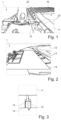
- the floating cover system 1 for storage tanks further comprises a floating raft 20 formed by a plurality of modular floating elements 21 connected one to the other at restraining joints 22 so as to form the tank cover.
- Said floating raft 20 which is part of said covering element and forms the actual "roof" of the tank, is provided with rigid connectors 25 having the function of efficiently transferring the concentrated loads to the floating raft 20.
- the connectors are made up of a box element 25a of suitable size to occupy the free space between the modular floats 21.
- the box element is completed by a tubular element 25b of adequate size to fit into the point of joining of the modular floats 21 and internally hollow in order to accommodate a threaded bar 26 for tightening of the joint by screwing one or more bolts 26a.
- the connector is used for structural connection to other elements of the floating cover system 1 according to the invention, such as in particular to the caissons 50 and to the tensioning system 12 of the sheet in waterproof fabric 11.
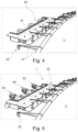
- the rigid connectors 25 are placed along the entire perimeter of the cover at variable centre distance and allow the connection of the floating raft 20 to the support elements 50, as can be seen for example in Figures 4 and 5 , and the tensioning of the membrane 11 which, by means of the perimeter metal tube 13 and the tensioning system 12, is fixed to the rigid connectors 25 placed at the floating raft and/or the support elements 50.
- Providing modular elements 21 that can be connected one to the other makes it possible to make the entire system modular, allowing the geometry of the cover to be adapted to storage tanks or vessels of various sizes and shapes (circular, rectangular, elliptical, etc.).
- the size and thickness of the modular elements 21 and their joining system are a function of the stresses transmitted to the floating raft 20 by the digestate. It is essential that the resistance in the plane is adequate for the tensile, compressive and shear stresses generated by the forces of contact with the digestate. It is also essential that the floating raft is adequately flexible out of the plane so that it can adapt to the unevenness of the surface of the digestate during the phases of entry and exit of the same to/from the tank/vessel. Out-of-plane flexibility also makes it possible to create valley points in the cover layer, making it possible for rainwater to drain off. The out-of-plane flexibility of the floating raft also allows the cover to lie on an uneven bottom with obstacles (the liquid inlet, suction and recirculation pipes) and to adapt to any abnormal waves of the liquid in the event of earthquakes or strong winds.
- obstacles the liquid inlet, suction and recirculation pipes
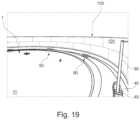
- the floating cover system 1 for storage tanks/vessels further comprises, fixed to the inner wall of the tank preferably with an interlocking type joint at its ends, one or more anti-rotation elements 30, in the example illustrated in the drawings made up of a vertical pole, suitable for limiting at least partially the movements of the cover element 10, 20 with respect to the tank 100.
- the anti-rotation pole 30 advantageously placed at a certain distance from the shell 101 of the tank, according to what can be seen in the accompanying drawings, allows a part of the stresses transmitted from the cover to the shell 101 in the plane XY to be absorbed.
- the roller system which will be described in greater detail here below, allows displacements in the vertical direction Z of the cover.
- the anti-rotation pole 30 represents the fixed point of the floating cover, and the cover is restrained thereto by means of the caissons 50, and in particular the rollers 40, as will be described here below.
- the interlocking joint enables part of the stresses developed by the floating cover during normal operation to be transferred to the shell, i.e. to the inner wall of the tank, preventing the floating raft from rotating around the centre of the tank.
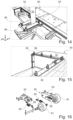
- the floating cover system 1 for storage tanks/vessels further comprises, acting between the anti-rotation pole 30 and the floating cover layer 10, a system of low-friction rollers 40 suitable for adequately constraining the cover by preventing rotation thereof in the plane XY without damaging either the anti-rotation pole 30 or the caisson 50.
- the rollers 40 constrain the horizontal movement in a direction, denoted by Y in the Cartesian reference of Figure 14 of the horizontal plane XY, preventing, in fact, the rotation of the floating cover layer 10 that could be caused by the stresses deriving from the vortical movements that may occur in the stored fluid.
- the roller system ensures a stroke with length defined in the design phase in order to manage the movements and deformations of the cover in that direction during operation.
- the rollers 40 instead allow movement in the vertical direction, denoted by Z in the abovementioned drawings.
- the contact surfaces of rollers 40 are made in Teflon or a suitable material to limit friction and wear over time as well as the risk of sparks (which could be a trigger for possible explosions).
- the core of the rollers 40 is preferably made with metal profiles to guarantee the required mechanical strength.
- the floating cover system 1 for storage tanks according to the present invention further comprises one or more metal caissons 50 to which the floating raft 20 is connected and which perform the function of an interface with the inner wall of the tank.
- buffer elements 60 are installed which allow the floating cover 1 to be kept at a sufficient distance from the inner wall of the tank: during the operations of emptying and/or filling, in fact the cover would tend to impact on the wall itself, damaging the wall, any layers of protective coating, the flap of the cover layer and the floating modules.
- the buffer elements 60 allow the forces on the XY plane to be absorbed. They are provided with wheels 61 to allow movements along the vertical Z.
- the wheel 61 is mounted on special wheel holders, or rather buffer holders, 59, made with perforated metal flanges 52 which allow the buffers 60 of the wheels 61 to be mounted and adjusted.
- each metal caisson 50 comprises a perforated upper plate 51 to which is restrained the floating raft 20 made with the floating modules 21 by means of rigid connectors.
- Each of said support elements 50 may have one or more flanges 52 for aspiration of the gas and a system of spacers 54 to facilitate the drainage of the gas at the vertical surface of contact between the wall of the tank and the floating raft.
- the same spacers 54 also act as ribs suitable for improving the mechanical resistance to the stresses exerted by the buffer elements 60 installed on said support elements 50.
- the support elements 50 are provided with hooks for lifting 53 and movement during phases of assembly and maintenance, with a horizontal flange 57 for C-clamping the floating raft, a vertical flange 58 appropriately dimensioned to ensure a "hydraulic trap" in line with that guaranteed by the cover layer (which is interrupted at the caissons).
- the support elements 50 perform the function of transferring to the buffers with wheels 60 (and subsequently to the layer 101) the actions due to the stresses generated by the movement of the liquid in contact with the floating cover 1.
- the buffers with wheels 60 in fact, cannot be connected directly to the modules in plastic material 21 because the maximum force for which they were designed would damage the single module 21 and it must therefore be distributed over several modules 21, a function performed by the caisson.
- the support elements 50 guarantee a stable and secure landing point during maintenance operations.
- the support elements 50 can also constitute a stable attachment point for the rails of a ladder that connects a balcony provided on the tank to the floating raft 20.
- the support elements 50 can be used to connect instrumentation and accessories that otherwise could not be connected directly to the cover fabric 10 or to the plastic material modules 21, such as the aspiration flanges 52 of the gas/malodorous emissions, low-friction rollers 40, sensors and data acquisition units and so on, as well as ensuring also the anti-rotation system of the cover itself.
- the interface between the support elements 50 and the cover layer 10 is formed by means of a mechanical fastening system with metal plates 55 and gaskets that guarantee the airtight seal thanks to the tightness exercised by the screws 56 (replaceable in the case of seizure).
- a plurality of buffer elements 60 provided with wheels 61 and shock absorbers 62 are interposed between the shell and the support elements 50, the latter being then connected to the floating raft 20.
- Said shock absorbers 62 are suitable for counteracting thrust forces that are exchanged between the buffer element 60 of said support element 50 and the inner wall of the tank/vessel 100.
- the buffer elements 60 when configured as described, they protrude radially from said caissons 50, said shock absorbers 62 acting along the radial direction.
- said wheels 61 of said buffer elements 60 are provided with a rubber lining to facilitate vertical movements of the floating raft 20 that take place during filling and emptying, so as to limit friction and wear damage to the shell 101 and to any protective coatings.
- Said buffer elements 60 can also advantageously comprise at least one wheel support pin 61 for transferring the load to the wheel holder assembly 63 and inserts in Teflon to limit friction between the metal components and eliminate the risk of sparks.
- a threaded bar system 64 can advantageously be provided for adjusting the position of the wheel 61 with respect to the wheel holder 63.
- the spring 62 allows the adjustment of the 'preload' level and improvement in force distribution. Thanks to the action of the springs 62, the wheel 61 orientates so as to work in adherence to the shell. Thanks to the action of the springs 62 it is also possible to improve the distribution of forces between the buffers 60 of the same caisson 50.
- a variable number of buffers 60 on each caisson 50 can be provided as a function of the force that has to be transferred from the raft 20 to the vertical wall of the vessel.
- the forces mainly take shape during the periods of rapid filling and emptying of the tank/vessel and vary as a function of the viscosity of the material and of the level of digestate in the same.
- the buffer element 60 or wheel assembly may be provided with flanges for the connection of additional floats 21 aimed at improving the flotation of the support element 50.
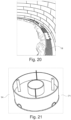
- the floating cover system 1 for storage tanks/vessels it advantageously comprises a water catchment system formed by means of localised lowerings 71 of the cover and the consequent formation of a water catchment and drainage cone.
- These water accumulation areas 71 is preferably circular, according to what is shown by way of example in Figure 21 , and of adequate diameter, indicatively around 2 metres in diameter according to the properties of the fabric and the conditions of use of the cover, so as not to tear the fabric in the case of swelling of the cover layer due to internal pressure or action of the wind.
- the localised lowering 71 constitutes a housing for the suction pump and must have a smooth contact surface that does not damage the cover layer and a suitable geometry, for example, the circular one shown in Figure 21 , with openings capable of conveying water to the pump aspiration point. It must also be easy to inspect (e.g. to facilitate the removal of leaves or of any dirt that may impede the normal operation of the pump).
- the cover layer is protected with additional layers of fabric and nonwoven fabric.
- Rainwater management is assisted by the tubular metal ring 13 for tensioning the membrane, which also has the function of constituting a barrier to the normal outflow of water along the edges which makes it converge in the area of action of the suction pump.
- the suction pump must have a system of feeding and outflow capable of adapting (by adjusting the length thereof) to the variable level of the liquid.
- the floating cover system 1 for storage tanks/vessels further comprises a system for capturing biogas or possible malodorous emissions deriving from the stored material.
- said biogas/emissions capturing system comprises an extraction pipe 80 connected to the support element 50 by means of an appropriate flange 52 at the drainage system of the support element 50 itself.
- said extraction pipe 80 is flexible and of adjustable length so as to be adapted to the variable level of the liquid contained in the tank. Further, said extraction pipe 80 is advantageously provided, for the adjustment of its length, with a drum 90 for the winding of said pipe, made so as to have a single high point, denoted by reference numeral 81 in Figure 23 , so as to allow the discharge of any condensation that may form in the course of the aspiration of the biogas/emissions.
- the length of the unwound fraction of said extraction pipe 80 can be adapted to the operating conditions by means of manual or automatic systems.
- the maximum length is reached, according to what can be seen by way of example in Figure 22 , when the raft 20 is at the lowest point of the storage tank 100, the minimum length is reached when the raft 20 is at the highest floating point.
- the maximum length of the extraction pipe 80 is therefore equal to the height of the tank, while the minimum length is equal to the difference between the height of the tank and the level of floating of the raft 20 when the tank is filled to its maximum level.
- a drum system 90 has been specifically implemented for the winding of the extraction pipe 80 suitable for simultaneously adjusting the length of this pipe 80 and the height of its upper coil 80a, rolled on the drum itself, as the level of digestate contained in the storage tank 100 and, therefore, of the cover 1 according to the present invention varies.
- Figure 23 shows the support device 91 of the extraction pipe 80 is suitable for supporting and moving the upper end of this pipe 80 in the winding and unwinding operations on and from the drum 90.
- This device 91 is installed externally to the storage tank 100.
- Said support device 91 for the extraction pipe comprises a vertically movable head 92 apt to support the upper end of said extraction pipe 80 and movable along the vertical axis Z by means of an adjustment system of the height of said head 92, in turn, comprising a crank 93 connected to motion transmission means 94 that act at the same time on both an adjustment mechanism of the height of the head 92 and on the rotation of the drum 90. Thanks to this support device 91 of the extraction pipe 80, the operator can adjust the height of the high point 81 by moving upwards or downwards said head 92 as a function of the position of the last coil, the highest one 80a, wound on the drum 90, in order, as said, to ensure the outflow of any condensation.
Landscapes
- Life Sciences & Earth Sciences (AREA)
- Microbiology (AREA)
- Biodiversity & Conservation Biology (AREA)
- Hydrology & Water Resources (AREA)
- Engineering & Computer Science (AREA)
- Environmental & Geological Engineering (AREA)
- Water Supply & Treatment (AREA)
- Chemical & Material Sciences (AREA)
- Organic Chemistry (AREA)
- Filling Or Discharging Of Gas Storage Vessels (AREA)
Applications Claiming Priority (1)
| Application Number | Priority Date | Filing Date | Title |
|---|---|---|---|
| IT102022000016872A IT202200016872A1 (it) | 2022-08-05 | 2022-08-05 | Sistema di copertura flottante per serbatoi di stoccaggio di matrici organiche ad utilizzo stagionale |
Publications (1)
| Publication Number | Publication Date |
|---|---|
| EP4317088A1 true EP4317088A1 (fr) | 2024-02-07 |
Family
ID=83900264
Family Applications (1)
| Application Number | Title | Priority Date | Filing Date |
|---|---|---|---|
| EP23187432.2A Pending EP4317088A1 (fr) | 2022-08-05 | 2023-07-25 | Système de couverture flottante pour réservoirs pour le stockage de matrices organiques pour une utilisation saisonnière |
Country Status (2)
| Country | Link |
|---|---|
| EP (1) | EP4317088A1 (fr) |
| IT (1) | IT202200016872A1 (fr) |
Citations (3)
| Publication number | Priority date | Publication date | Assignee | Title |
|---|---|---|---|---|
| CA2252294A1 (fr) * | 1998-10-30 | 2000-04-30 | Claude J. Degarie | Dispositif flottant intermediaire pour soutenir un couvre-membrane |
| ITCR20010010A1 (it) * | 2001-12-13 | 2003-06-13 | Ecomembrane Srl | Elemento modulare galleggiante per la realizzazione di un sistema di copertura di una vasca contenente un liquido, atto alla captazione di g |
| EP2966963B1 (fr) * | 2013-01-09 | 2017-03-29 | Engel, Rémy Marie Arnaud | Dispositif de récupération séparée de biogaz et d'eau de pluie pour ouvrage de stockage d'effluents liquides chargés tels que des lisiers |
-
2022
- 2022-08-05 IT IT102022000016872A patent/IT202200016872A1/it unknown
-
2023
- 2023-07-25 EP EP23187432.2A patent/EP4317088A1/fr active Pending
Patent Citations (3)
| Publication number | Priority date | Publication date | Assignee | Title |
|---|---|---|---|---|
| CA2252294A1 (fr) * | 1998-10-30 | 2000-04-30 | Claude J. Degarie | Dispositif flottant intermediaire pour soutenir un couvre-membrane |
| ITCR20010010A1 (it) * | 2001-12-13 | 2003-06-13 | Ecomembrane Srl | Elemento modulare galleggiante per la realizzazione di un sistema di copertura di una vasca contenente un liquido, atto alla captazione di g |
| EP2966963B1 (fr) * | 2013-01-09 | 2017-03-29 | Engel, Rémy Marie Arnaud | Dispositif de récupération séparée de biogaz et d'eau de pluie pour ouvrage de stockage d'effluents liquides chargés tels que des lisiers |
Also Published As
| Publication number | Publication date |
|---|---|
| IT202200016872A1 (it) | 2024-02-05 |
Similar Documents
| Publication | Publication Date | Title |
|---|---|---|
| CA2502236C (fr) | Dispositif de stockage situe au fond de la mer | |
| US5829621A (en) | Guide pole fitting seal for floating roof storage tanks | |
| EP2175015B1 (fr) | Couvercle flottant pour des réservoirs à liquides | |
| NO864843L (no) | Fremgangsmaate for utlegging av undervanns roerledninger fra land, saerlig for ilandfoeringsanlegg. | |
| EP4317088A1 (fr) | Système de couverture flottante pour réservoirs pour le stockage de matrices organiques pour une utilisation saisonnière | |
| CN114636090A (zh) | 一种覆土双壳式液态烃低温储存系统 | |
| US8353142B2 (en) | System and method for sealing sump covers | |
| US5238844A (en) | Sludge digester | |
| JP4954914B2 (ja) | 水中構造物の仮締切工法及び仮締切用構造体 | |
| CN2510436Y (zh) | 储油罐用的组装式外浮盘 | |
| US4971217A (en) | Tensioned floatation cover with slip ring connection | |
| US20210300176A1 (en) | Fuel Tank with Internal Bladder and Method | |
| US11186432B2 (en) | External floating roof tank shell extension | |
| US3154214A (en) | Roof drain for floating roof tank | |
| US6247278B1 (en) | Sewage digester cap | |
| US5609267A (en) | Corrosion-resistant storage tank for runoff liquids | |
| CZ294183B6 (cs) | Protiúniková výstelka pro nádrže a způsob vybavování nádrží touto protiúnikovou výstelkou | |
| JP2018203360A (ja) | タンクの付帯設備 | |
| EP2397540A1 (fr) | Réservoir de gaz | |
| CN209537075U (zh) | 一种沉降式曝气系统 | |
| US10683162B2 (en) | Digester cover left-in-place ballast ring | |
| US10689189B1 (en) | External floating roof tank shell extension | |
| CA3149974C (fr) | Récipient étanche aux gaz | |
| CN110393092B (zh) | 一种半架空用于存储散粮的多功能粮仓 | |
| CN214691299U (zh) | 一种可调节浮盘支柱 |
Legal Events
| Date | Code | Title | Description |
|---|---|---|---|
| PUAI | Public reference made under article 153(3) epc to a published international application that has entered the european phase |
Free format text: ORIGINAL CODE: 0009012 |
|
| STAA | Information on the status of an ep patent application or granted ep patent |
Free format text: STATUS: THE APPLICATION HAS BEEN PUBLISHED |
|
| AK | Designated contracting states |
Kind code of ref document: A1 Designated state(s): AL AT BE BG CH CY CZ DE DK EE ES FI FR GB GR HR HU IE IS IT LI LT LU LV MC ME MK MT NL NO PL PT RO RS SE SI SK SM TR |
|
| P01 | Opt-out of the competence of the unified patent court (upc) registered |
Effective date: 20240212 |
|
| STAA | Information on the status of an ep patent application or granted ep patent |
Free format text: STATUS: REQUEST FOR EXAMINATION WAS MADE |
|
| 17P | Request for examination filed |
Effective date: 20240801 |
|
| RBV | Designated contracting states (corrected) |
Designated state(s): AL AT BE BG CH CY CZ DE DK EE ES FI FR GB GR HR HU IE IS IT LI LT LU LV MC ME MK MT NL NO PL PT RO RS SE SI SK SM TR |