EP4317570A2 - Spannrahmensystem mit funktion zur automatischen korrektur von gewebe auf bildbasis - Google Patents
Spannrahmensystem mit funktion zur automatischen korrektur von gewebe auf bildbasis Download PDFInfo
- Publication number
- EP4317570A2 EP4317570A2 EP22846033.3A EP22846033A EP4317570A2 EP 4317570 A2 EP4317570 A2 EP 4317570A2 EP 22846033 A EP22846033 A EP 22846033A EP 4317570 A2 EP4317570 A2 EP 4317570A2
- Authority
- EP
- European Patent Office
- Prior art keywords
- fabric
- design pattern
- discharged
- conveyor belt
- tenter
- Prior art date
- Legal status (The legal status is an assumption and is not a legal conclusion. Google has not performed a legal analysis and makes no representation as to the accuracy of the status listed.)
- Granted
Links
Images


Classifications
-
- D—TEXTILES; PAPER
- D06—TREATMENT OF TEXTILES OR THE LIKE; LAUNDERING; FLEXIBLE MATERIALS NOT OTHERWISE PROVIDED FOR
- D06C—FINISHING, DRESSING, TENTERING OR STRETCHING TEXTILE FABRICS
- D06C3/00—Stretching, tentering or spreading textile fabrics; Producing elasticity in textile fabrics
- D06C3/02—Stretching, tentering or spreading textile fabrics; Producing elasticity in textile fabrics by endless chain or like apparatus
-
- D—TEXTILES; PAPER
- D06—TREATMENT OF TEXTILES OR THE LIKE; LAUNDERING; FLEXIBLE MATERIALS NOT OTHERWISE PROVIDED FOR
- D06C—FINISHING, DRESSING, TENTERING OR STRETCHING TEXTILE FABRICS
- D06C23/00—Making patterns or designs on fabrics
-
- D—TEXTILES; PAPER
- D06—TREATMENT OF TEXTILES OR THE LIKE; LAUNDERING; FLEXIBLE MATERIALS NOT OTHERWISE PROVIDED FOR
- D06H—MARKING, INSPECTING, SEAMING OR SEVERING TEXTILE MATERIALS
- D06H3/00—Inspecting textile materials
- D06H3/08—Inspecting textile materials by photo-electric or television means
-
- D—TEXTILES; PAPER
- D06—TREATMENT OF TEXTILES OR THE LIKE; LAUNDERING; FLEXIBLE MATERIALS NOT OTHERWISE PROVIDED FOR
- D06H—MARKING, INSPECTING, SEAMING OR SEVERING TEXTILE MATERIALS
- D06H3/00—Inspecting textile materials
- D06H3/12—Detecting or automatically correcting errors in the position of weft threads in woven fabrics
-
- D—TEXTILES; PAPER
- D06—TREATMENT OF TEXTILES OR THE LIKE; LAUNDERING; FLEXIBLE MATERIALS NOT OTHERWISE PROVIDED FOR
- D06C—FINISHING, DRESSING, TENTERING OR STRETCHING TEXTILE FABRICS
- D06C2700/00—Finishing or decoration of textile materials, except for bleaching, dyeing, printing, mercerising, washing or fulling
- D06C2700/02—Tenters for tentering or drying fabrics
-
- D—TEXTILES; PAPER
- D06—TREATMENT OF TEXTILES OR THE LIKE; LAUNDERING; FLEXIBLE MATERIALS NOT OTHERWISE PROVIDED FOR
- D06C—FINISHING, DRESSING, TENTERING OR STRETCHING TEXTILE FABRICS
- D06C2700/00—Finishing or decoration of textile materials, except for bleaching, dyeing, printing, mercerising, washing or fulling
- D06C2700/31—Methods for making patterns on fabrics, e.g. by application of powder dye, moiréing, embossing
Definitions
- the present disclosure relates to a tenter system having a function of automatically correcting a fabric on the basis of an image.
- a value of a fabric as a product suitable for an intended use cannot be secured just by de-sizing, scouring, bleaching, or dying the fabric.
- the fabric in a state where processing has not yet been completed, the fabric has a rough feel and is not suitable for use as the fabric, and thus, the fabric is nothing more than a semi-finished product.
- the original purpose of tentering processes is to increase product value by making excellent products through a tenter processing process appropriate for various fabrics.
- a tenter machine which is introduced in the process that occupies the most important part in dyeing of various fabrics, supplies hot air at a temperature set according to a type of the fabric to the fabric being transferred, thereby correcting a density for a certain width or length of the fabric and providing pre-setting, water repellent, flexible processing, pre-shrinking, anti-fouling effects, or the like.
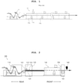
- Fig. 1 is a diagram illustrating the structure of a typical tentering process.
- a chemical tank 2 and a tenter machine 10 are installed along the transfer path of a supplied fabric 1.
- the chemical tank 2 contains chemicals such as dyes and softeners inside the chemical tank, and a plurality of rollers are installed on an upper portion and an inner side of an inlet side of the chemical tank 2 to guide the fabric 1 in a state where the fabric is immersed in the chemicals and then transported.
- a mangle 3 including a pair of rollers is installed on the upper portion of a discharge side of the chemical tank 2 to spread the fabric 1 and primarily remove foreign substances and chemicals on the fabric 1.
- the tenter machine (10) includes a plurality of drying chambers 10a and 10b through which the fabric 1 passes inside the tenter machine, a hot air supplier 11a is provided in each of the drying chambers 10a and 10b to spray high-temperature air toward the fabric 1, and thus, chemicals and water remaining on the fabric 1 after passing through the mangle 3 are removed by heat.
- a design pattern of the fabric finally obtained by introducing the fabric having a certain design pattern into the tenter machine, subjecting the fabric to the tentering process, and cooling the fabric is shrunk or twisted in a lateral direction and/or a longitudinal direction compared to a design pattern of the initially introduced fabric, and thus, deformation may occur.
- a lateral spacing of the design pattern may be narrow as the fabric subjected to the tentering process is shrunk in the lateral direction
- a longitudinal spacing of the design pattern may be narrow as the fabric subjected to the tentering process is shrunk in the longitudinal direction
- left and right deformation of the design pattern may occur.
- the worker manually corrects the lateral spacing and/or the longitudinal spacing of the introduced fabric by inspecting the design pattern of the fabric that is subjected to the tentering process and then finally obtained through cooling and checking for deformation of the design pattern to correct the deformation. Accordingly, not only is the correction of the design pattern not precise, but work efficiency is also significantly reduced.
- An object of the present disclosure is to provide a tenter system having a function of automatically correcting a fabric on the basis of an image capable of automatically correcting a pattern of an introduced fabric in one aspect.
- Another object of the present disclosure is to provide a method of automatically correcting a fabric by a tenter system on the basis of an image capable of automatically correcting a pattern of an introduced fabric in another aspect.
- a tenter system having a function of automatically correcting a fabric on the basis of an image
- the tenter system including: a tenter machine; an introduced-fabric design pattern correction unit provided behind the tenter machine and configured to correct an introduced-fabric design pattern of an input fabric introduced into the tenter machine; a first scanning unit provided in front of the tenter machine and configured to scan a design pattern of a discharged fabric discharged from the tenter machine to acquire a discharged-fabric design pattern image; and a central processing unit configured to communicate with the introduced-fabric design pattern correction unit and the first scanning unit, in which when a standard design pattern image is input from a user, the discharged-fabric design pattern image is provided by the first scanning unit, the standard design pattern image and the discharged-fabric design pattern image are compared with each other, and a comparison result exceeds a predetermined setting range, the central processing unit controls the introduced-fabric design pattern correction unit to correct the introduced-fabric design pattern by adjusting at least one of
- a method of automatically correcting a fabric by a tenter system on the basis of an image including: a standard design pattern image input step of inputting a standard design pattern image; a discharged-fabric design pattern image acquisition step of acquiring a discharged-fabric design pattern image of a discharged fabric discharged from a tenter machine; a discharged fabric design pattern deformation determination step of comparing the input standard design pattern image with the obtained discharged-fabric design pattern image and determining as discharged fabric design pattern deformation when a comparison result exceeds a predetermined setting range; and an introduced-fabric design pattern correction step of correcting the introduced-fabric design pattern by adjusting at least one of a lateral width and a supply speed of the introduced fabric introduced to the tenter machine according to the determination of deformation of the discharged fabric design pattern.
- a tenter system can provide an image-based automatic fabric correction function capable of automatically correcting the design pattern of the fabric.
- the tenter system fabric automatic correction method can provide an image-based tenter system fabric automatic correction function that can automatically correct the design pattern of the fabric.
- FIG. 2 is an installation diagram illustrating a tenter system according to one aspect of the present disclosure
- FIG. 3 is a plan view of the tenter system according to one aspect of the present disclosure
- FIG. 4 is a cross-sectional view taken along the line A-A' of FIG. 3
- FIG. 5 is a cross-sectional view taken along line B-B' of FIG. 3 .
- a tenter system 100 includes a tenter machine 130, an introduced-fabric design pattern correction unit 120, a first scanning unit 140, and a central processing unit (not illustrated). Meanwhile, the tenter system 100 further includes a fabric supply unit 110.
- the fabric supply unit 110 and the tenter machine 130 are well known.
- a front refers to the front of the direction in which a fabric 101 moves
- a rear refers to the rear of the direction in which the fabric 101 moves.
- the fabric 101 After the fabric 101 is supplied to the tenter system 100 through the fabric supply unit 110, the fabric sequentially passes through the introduced-fabric design pattern correction unit 120, the tenter machine 130, and the first scanning unit 140 and is finally discharged.
- the introduced-fabric design pattern correction unit 120 is provided at the rear of the tenter machine 130 and is configured to correct the introduced-fabric design pattern of the introduced fabric introduced to the tenter machine 130.
- the first scanning unit 140 is provided in front of the tenter machine 130 and is configured to scan the design pattern of the discharged fabric discharged from the tenter machine 130 to obtain a discharged-fabric design pattern image.
- the central processing unit (not illustrated) is configured to communicate with the introduced-fabric design pattern correction unit 120 and the first scanning unit 140.
- the central processing unit may control the introduced-fabric design pattern correction unit 120 to correct the introduced-fabric design pattern by adjusting at least one of a lateral width and supply speed of the introduced fabric.
- FIG. 6 is a diagram illustrating a standard design pattern 200 according to one embodiment of the present disclosure
- FIG. 7 is a diagram presented by overlapping the standard design pattern 200 and a fabric design pattern 300 formed on a fabric according to one embodiment of the present disclosure.
- the fabric design patterns 300 formed on the fabric 101 are presented, and the standard design pattern 200 is placed to overlap the fabric design pattern 300 located on the leftmost side among the fabric design patterns 300.
- the standard design pattern 200 is the original design pattern of the fabric design pattern 300 formed on the fabric 101. That is, when weaving the fabric 101, the fabric design pattern 300 woven by a loom (not illustrated) based on the standard design pattern 200 is formed on the fabric 101.
- the fabric that is, introduced fabric
- the fabric design pattern 300 woven based on the standard design pattern 200 undergoes a tentering process and is then cooled, the fabric may be shrunk in a lateral direction and/or longitudinal direction, twisted, and thus, deformed. Therefore, the design pattern of the finally obtained fabric (that is, discharged fabric) may differ significantly from the design pattern of the introduced fabric introduced to the tenter machine in a lateral spacing and/or longitudinal spacing, or deformation may occur in the design pattern of the discharged fabric.
- the present disclosure is intended to correct for the deformation.
- the user Before performing the tentering process, the user can input the standard design pattern image obtained by photographing the standard design pattern 200 into the central processing unit (not illustrated).
- the fabric introduced into the tenter machine 130 may undergo the tentering process while passing through the tenter machine 130 and may then be deformed by shrinking or twisting in the lateral direction and/or longitudinal direction as the fabric is cooled. Therefore, the design pattern of the discharged fabric that is finally obtained may have significant differences in the lateral spacing and/or longitudinal spacing from the design pattern of the introduced fabric introduced to the tenter machine, or the deformation may occur.
- the design pattern of the finally obtained discharged fabric can be matched to the standard design pattern.
- the tenter system 100 further includes a discharged fabric cooling unit 150, and the discharged fabric cooling unit 150 is configured to be disposed between the tenter machine 130 and a first scanning unit 140.
- the discharged fabric cooling unit 150 is well known.
- the introduced-fabric design pattern correction unit 120 includes a fabric transfer conveyor belt 121.
- the fabric transfer conveyor belt 121 includes a first fabric transfer conveyor belt 121a and a second fabric transfer conveyor belt 121b which are disposed to be spaced apart from each other on the left and right sides of the introduced fabric and are controlled independently.
- the first fabric transfer conveyor belt 121a is configured to transfer the left edge of the introduced fabric
- the second fabric transfer conveyor belt 121b is configured to transfer the right edge of the introduced fabric.
- the first fabric transfer conveyor belt 121a and the second fabric transfer conveyor belt 121b each include fabric transfer pins 123a and 123b formed to protrude upward. More specifically, the first fabric transfer conveyor belt 121a is configured so that the left edge of the introduced fabric is fixed to the first fabric transfer pin 123a and transferred. Similarly, the second fabric transfer conveyor belt 121b is configured so that the right edge of the introduced fabric is fixed to the second fabric transfer pin 123b and transferred.
- the introduced-fabric design pattern correction unit 120 further includes a fabric fixing roller 122 that is in contact with the upper surface of the fabric 101 and rotates in a state of pressing the fabric 101 downward toward the fabric transfer conveyor belt 121.
- the fabric fixing roller 122 includes a first fabric fixing roller 122a and a second fabric fixing roller 122b that press the first fabric transfer conveyor belt 121a and the second fabric transfer conveyor belt 121b downward, respectively.
- At least one of the first fabric transfer conveyor belt 121a and the second fabric transfer conveyor belt 121b is configured to be movable in the lateral direction to adjust the lateral spacing of the introduced-fabric design pattern. More specifically, the left edge of the introduced fabric may be fixed to the first fabric transfer pin 123a and transferred, and the right edge of the introduced fabric may be fixed to the second fabric transfer pin 123b and transferred.
- the introduced fabric is also stretched in the lateral direction, ultimately widening the lateral spacing of the introduced-fabric design pattern.
- At least one of the first fabric transfer conveyor belt 121a and the second fabric transfer conveyor belt 121b is configured to adjust the longitudinal spacing of the introduced-fabric design pattern and adjust a supply speed of the introduced fabric. More specifically, as described above, the left edge of the introduced fabric may be fixed to the first fabric transfer pin 123a and transferred, and the right edge of the introduced fabric may be fixed to the second fabric transfer pin 123b and transferred.
- the central processing unit when the central processing unit (not illustrated) compares the lateral spacing of the standard design pattern image with the lateral spacing of the discharged-fabric design pattern image and the comparison result exceeds a predetermined setting range, the central processing unit controls the introduced-fabric design pattern correction unit 120 to correct the introduced-fabric design pattern by moving at least one of the first fabric transfer conveyor belt 121a and the second fabric transfer conveyor belt 121b in a lateral direction.
- the introduced fabric also stretches in lateral direction, ultimately widening the lateral spacing of the introduced-fabric design pattern.
- the central processing unit when the central processing unit (not illustrated) compares the longitudinal spacing of the standard design pattern image with the longitudinal spacing of the discharged-fabric design pattern image and the comparison result exceeds a predetermined setting range, the central processing unit controls the introduced-fabric design pattern correction unit to correct the introduced-fabric design pattern by adjusting the rotation speed of at least one of the first fabric transfer conveyor belt 121a and the second fabric transfer conveyor belt 121b.
- the central processing unit when the central processing unit compares the standard design pattern image and the discharged-fabric design pattern image and distortion of the discharged-fabric design pattern image occurs, the central processing unit controls the fabric design pattern correction unit to correct the introduced-fabric design pattern by increasing or decreasing any one of the rotation speeds of the first fabric transfer conveyor belt 121a and a rotation speed of the second fabric transfer conveyor belt 121b.
- the left edge of the introduced fabric may be fixed to the first fabric transfer pin 123a and transferred, and the right edge of the introduced fabric may be fixed to the second fabric transfer pin 123b and transferred.
- control of the introduced-fabric design pattern correction unit by the central processing unit may be performed by a machine learning method.
- FIG. 8 is an installation diagram illustrating a tenter system according to another aspect of the present disclosure
- FIG. 9 is a plan view of the tenter system according to another aspect of the present disclosure
- FIG. 10 is a cross-sectional view taken along line C-C' of FIG. 9 .
- the tenter system of the present disclosure further includes a second scanning unit 160 which is provided between the design pattern correction unit 120 and the tenter machine 130 and is configured to acquire the introduced-fabric design pattern image by scanning the design pattern of the introduced fabric after passing through the design pattern correction unit 120.
- the central processing unit is configured to receive the introduced-fabric design pattern image by communicating with the second scanning unit 160.
- the central processing unit may control the introduced-fabric design pattern correction unit to correct the introduced-fabric design pattern by adjusting at least one of the lateral width and the supply speed of the introduced fabric.
- the central processing unit may control the fabric design pattern correction unit to correct the introduced-fabric design pattern by increasing or decreasing any one of the rotation speed of the first fabric transfer conveyor belt 121a and the rotation speed of the second fabric transfer conveyor belt 121b.
- a method of automatically correcting a fabric by a tenter system on the basis of an image including a standard design pattern image input step of inputting a standard design pattern image, a discharged-fabric design pattern image acquisition step of acquiring a discharged-fabric design pattern image of a discharged fabric discharged from a tenter machine, a discharged fabric design pattern deformation determination step of comparing the input standard design pattern image with the obtained discharged-fabric design pattern image and determining as discharged fabric design pattern deformation when a comparison result exceeds a predetermined setting range, and an introduced-fabric design pattern correction step of correcting the introduced-fabric design pattern by adjusting at least one of a lateral width and a supply speed of the introduced fabric introduced to the tenter machine according to the determination of deformation of the discharged fabric design pattern.
- the discharged fabric design pattern deformation determination step includes a lateral deformation determination step of comparing the lateral spacing of the standard design pattern image and the lateral spacing of the discharged-fabric design pattern image and determining as discharged fabric design pattern lateral deformation when the comparison result exceeds a predetermined setting range
- the introduced-fabric design pattern correction step includes an introduced-fabric design pattern lateral correction step of correcting the introduced-fabric design pattern by adjusting the lateral width of the introduced fabric introduced to the tenter machine according to the discharged fabric design pattern lateral deformation determination.
- the discharged fabric design pattern deformation determination step includes a lateral deformation determination step of comparing the longitudinal spacing of the standard design pattern image with the longitudinal spacing of the discharged-fabric design pattern image and determining as discharged fabric design pattern lateral deformation when the comparison result exceeds a predetermined setting range
- the introduced-fabric design pattern correction step includes an introduced-fabric design pattern lateral correction step of correcting the introduced-fabric design pattern by adjusting the supply speed of the introduced fabric introduced to the tenter machine according to the discharged fabric design pattern lateral deformation determination and adjusting a lateral width.
- the discharged fabric design pattern deformation determination step includes a distortion deformation determination step of comparing the standard design pattern image and the discharged-fabric design pattern image and determining as discharged fabric design distortion pattern deformation when distortion of the discharged-fabric design pattern image occurs
- the introduced-fabric design pattern correction step includes an introduced-fabric design pattern distortion correction step of correcting the introduced-fabric design pattern by increasing or reducing any one of the supply speeds of the left and right edges of the introduced fabric introduced to the tenter machine according to the discharged fabric design pattern distortion deformation determination to adjust the distortion.
Landscapes
- Engineering & Computer Science (AREA)
- Textile Engineering (AREA)
- Chemical & Material Sciences (AREA)
- Materials Engineering (AREA)
- Treatment Of Fiber Materials (AREA)
Applications Claiming Priority (2)
| Application Number | Priority Date | Filing Date | Title |
|---|---|---|---|
| KR1020210094317A KR102549835B1 (ko) | 2021-07-19 | 2021-07-19 | 영상기반 원단자동보정 기능이 구비된 텐터 시스템 |
| PCT/KR2022/007556 WO2023003161A2 (ko) | 2021-07-19 | 2022-05-27 | 영상기반 원단자동보정 기능이 구비된 텐터 시스템 |
Publications (4)
| Publication Number | Publication Date |
|---|---|
| EP4317570A2 true EP4317570A2 (de) | 2024-02-07 |
| EP4317570A4 EP4317570A4 (de) | 2025-03-05 |
| EP4317570C0 EP4317570C0 (de) | 2026-01-14 |
| EP4317570B1 EP4317570B1 (de) | 2026-01-14 |
Family
ID=84978745
Family Applications (1)
| Application Number | Title | Priority Date | Filing Date |
|---|---|---|---|
| EP22846033.3A Active EP4317570B1 (de) | 2021-07-19 | 2022-05-27 | Spannrahmensystem mit funktion zur automatischen korrektur von gewebe auf bildbasis |
Country Status (5)
| Country | Link |
|---|---|
| US (1) | US12152328B2 (de) |
| EP (1) | EP4317570B1 (de) |
| KR (2) | KR102549835B1 (de) |
| CN (1) | CN117203387B (de) |
| WO (1) | WO2023003161A2 (de) |
Families Citing this family (2)
| Publication number | Priority date | Publication date | Assignee | Title |
|---|---|---|---|---|
| KR102900742B1 (ko) * | 2023-04-04 | 2025-12-16 | 다이텍연구원 | 텐터 가공 관리 시스템 |
| KR20250020195A (ko) | 2023-08-03 | 2025-02-11 | 주식회사 엘지에너지솔루션 | 배터리 진단 장치, 배터리 진단 방법 및 배터리 진단 시스템 |
Family Cites Families (29)
| Publication number | Priority date | Publication date | Assignee | Title |
|---|---|---|---|---|
| US2219213A (en) * | 1939-10-14 | 1940-10-22 | Utica Willowvaie Bleaching Com | Method and apparatus for correcting bow in woven material |
| US2311406A (en) * | 1942-03-24 | 1943-02-16 | Gen Electric | Measuring lengths and correcting skew and bow in woven material |
| US2355465A (en) * | 1943-10-02 | 1944-08-08 | United Merchants & Mfg | Device to detect skew in fabrics |
| US2587224A (en) * | 1949-12-03 | 1952-02-26 | John D Robertson | Weft-straightening apparatus |
| US2737700A (en) * | 1952-02-19 | 1956-03-13 | Tubular Textile Machine Corp | Stripe matching machine |
| US2795029A (en) * | 1954-06-25 | 1957-06-11 | Robertson Co H H | Skew detecting method and apparatus |
| DE1067401B (de) * | 1957-04-02 | 1959-10-22 | Albert Leimer, Augsburg | Vorrichtung zum Geraderichten von verzogenen Schußfäden in laufenden Gewebebahnen |
| US3146511A (en) * | 1960-09-12 | 1964-09-01 | Frederick W Hoffman | Weft-straightening apparatus and method |
| US3751774A (en) * | 1969-11-06 | 1973-08-14 | Mount Hope Machinery Ltd | Apparatus for correcting weft distortions in woven webs |
| US3721809A (en) * | 1971-04-05 | 1973-03-20 | Strandberg Eng Labor Inc | Automatic thread counter and controller for fabric processing apparatus |
| US4017722A (en) * | 1975-04-11 | 1977-04-12 | Measurex Corporation | Control system for textile tenter frame |
| US4656360A (en) * | 1984-10-19 | 1987-04-07 | Sw Industries, Inc. | Optical sensing system for determining the orientation of weft threads in a wide variety of fabrics |
| BE1000294A3 (nl) * | 1987-02-05 | 1988-10-11 | Wetenschappelijk En Tech Ct Va | Werkwijze voor het meten van de garendichtheid van een weefsel of de steekdichtheid van een breisel en inrichting voor het uitvoeren van deze werkwijze. |
| US5035030A (en) * | 1990-04-05 | 1991-07-30 | Riccardo Pellari | Apparatus for controlling and straightening weft and/or warp fabric patterns |
| DE19609928C2 (de) * | 1996-03-14 | 1998-02-26 | Monforts Textilmaschinen Gmbh | Spannmaschine für eine textile Warenbahn |
| KR100234593B1 (ko) | 1997-01-09 | 1999-12-15 | 정의훈 | 직물의 고속 검사방법 |
| KR100920488B1 (ko) | 2007-11-05 | 2009-10-08 | 최영일 | 고정밀성의 감지유닛이 마련된 포목 교정기 |
| KR101046217B1 (ko) | 2009-09-18 | 2011-07-04 | (주)세왕섬유 | 신축성 직물 텐터 공정용 변부 말림 방지 장치 및 방법 |
| KR100933976B1 (ko) * | 2009-09-29 | 2009-12-28 | 주식회사 로텍 | 직물밀도측정시스템 및 이를 이용한 직물밀도측정방법 |
| KR101336103B1 (ko) * | 2012-05-04 | 2013-12-03 | 주식회사 삼일기계 | 텐터기의 통합제어 시스템 |
| KR101427077B1 (ko) * | 2013-06-28 | 2014-08-13 | (주)벨텍코리아 | 직물의 교정, 가공 및 바이어스 직물 제조장치 |
| KR101520745B1 (ko) * | 2014-06-03 | 2015-05-20 | 대림스타릿 주식회사 | 자동으로 염색물의 폭이 조절되는 염색물 건조용 연속 텐터 |
| CN105741301B (zh) * | 2016-02-04 | 2018-10-23 | 东华大学 | 基于拉格朗日插值法的自动验布机走布速度不匀的图像矫正方法 |
| KR20170108634A (ko) * | 2016-03-18 | 2017-09-27 | 김건우 | 원단의 열셋팅기 |
| CN209039839U (zh) * | 2018-10-24 | 2019-06-28 | 常州宏大智能装备产业发展研究院有限公司 | 带前馈检测的整纬整花机 |
| CN211171259U (zh) * | 2019-12-09 | 2020-08-04 | 浙江鸿盛环保科技集团有限公司 | 一种模块化后整理系统 |
| IT202000004072A1 (it) * | 2020-02-27 | 2021-08-27 | Orox Group Srl | Sistema di identificazione di difetti su tessuti, relativa apparecchiatura e relativo metodo |
| KR102270814B1 (ko) * | 2020-03-02 | 2021-06-29 | 주식회사 삼하염직 | 위곡 현상을 방지한 신발 원단 후가공용 텐터 장치 |
| CN111851039A (zh) * | 2020-08-24 | 2020-10-30 | 常州宏大智能装备产业发展研究院有限公司 | 一种织物整纬或整纬整花装置及方法 |
-
2021
- 2021-07-19 KR KR1020210094317A patent/KR102549835B1/ko active Active
-
2022
- 2022-05-27 CN CN202280031169.6A patent/CN117203387B/zh active Active
- 2022-05-27 WO PCT/KR2022/007556 patent/WO2023003161A2/ko not_active Ceased
- 2022-05-27 US US18/286,887 patent/US12152328B2/en active Active
- 2022-05-27 EP EP22846033.3A patent/EP4317570B1/de active Active
-
2023
- 2023-06-26 KR KR1020230082238A patent/KR20230101779A/ko not_active Abandoned
Also Published As
| Publication number | Publication date |
|---|---|
| US12152328B2 (en) | 2024-11-26 |
| EP4317570A4 (de) | 2025-03-05 |
| EP4317570C0 (de) | 2026-01-14 |
| KR20230101779A (ko) | 2023-07-06 |
| WO2023003161A3 (ko) | 2023-03-16 |
| US20240191415A1 (en) | 2024-06-13 |
| CN117203387B (zh) | 2026-02-03 |
| CN117203387A (zh) | 2023-12-08 |
| KR20230013500A (ko) | 2023-01-26 |
| EP4317570B1 (de) | 2026-01-14 |
| WO2023003161A2 (ko) | 2023-01-26 |
| KR102549835B1 (ko) | 2023-06-29 |
Similar Documents
| Publication | Publication Date | Title |
|---|---|---|
| EP4317570A2 (de) | Spannrahmensystem mit funktion zur automatischen korrektur von gewebe auf bildbasis | |
| EP0942090B1 (de) | Vorrichtung zur behandlung von stoffbahnen | |
| WO1998037268A1 (en) | Method and apparatus for striped patterning of dyed fabric by hydrojet treatment | |
| US20060053840A1 (en) | Device for preparing textiles | |
| US3402443A (en) | Cloth straightening apparatus | |
| US20050122511A1 (en) | Device for finishing denim woven fabric | |
| CN209759807U (zh) | 一种定型机的纺织品纠偏机构 | |
| US2120536A (en) | Method and apparatus for preshrinking cloth | |
| CN104499228A (zh) | 快速透气降温t恤面料花染装置花染面料生产工艺 | |
| KR101591906B1 (ko) | 섬유의 연속전처리 방법 | |
| US6520216B2 (en) | Process for obtaining a woven cloth | |
| CA2205434C (en) | Belt-type woven material processing apparatus | |
| EP3850140B1 (de) | Maschine zur kontinuierlichen behandlung von gewebe, insbesondere zur kontrolle der dimensionsstabilität | |
| US5706995A (en) | Apparatus for the treatment of cloth strip with metal-surface rollers | |
| EP1520924B1 (de) | Vorrichtung und Verfahren zum Drucken auf Garnen und Gewebe aus solchen bedruckten Garnen | |
| CN104631023A (zh) | 弹力织物平缩预定形工艺技术 | |
| CA1135038A (en) | Machine for and method of producing treating or finishing a fabric | |
| CN119753987B (zh) | 一种基于纺织品磨毛机的磨毛处理效果分析方法及系统 | |
| WO2008039588A1 (en) | In-line system for processing textile material | |
| CN100497788C (zh) | 平幅水洗预缩装置和平幅水洗预缩工艺 | |
| TR2024009546U5 (tr) | Sanfor maki̇nesi̇ i̇çi̇n desen ve dokuma atkisi düzeltme aparati | |
| CN111705495A (zh) | 织物及其加工方法 | |
| CN1564893A (zh) | 粗斜纹布整理方法 | |
| KR20100120573A (ko) | 경사 염색 제직 장치 | |
| JPH08188959A (ja) | セルロース繊維布帛の寸法制御装置 |
Legal Events
| Date | Code | Title | Description |
|---|---|---|---|
| STAA | Information on the status of an ep patent application or granted ep patent |
Free format text: STATUS: THE INTERNATIONAL PUBLICATION HAS BEEN MADE |
|
| PUAI | Public reference made under article 153(3) epc to a published international application that has entered the european phase |
Free format text: ORIGINAL CODE: 0009012 |
|
| STAA | Information on the status of an ep patent application or granted ep patent |
Free format text: STATUS: REQUEST FOR EXAMINATION WAS MADE |
|
| 17P | Request for examination filed |
Effective date: 20231031 |
|
| AK | Designated contracting states |
Kind code of ref document: A2 Designated state(s): AL AT BE BG CH CY CZ DE DK EE ES FI FR GB GR HR HU IE IS IT LI LT LU LV MC MK MT NL NO PL PT RO RS SE SI SK SM TR |
|
| R17P | Request for examination filed (corrected) |
Effective date: 20231026 |
|
| DAV | Request for validation of the european patent (deleted) | ||
| DAX | Request for extension of the european patent (deleted) | ||
| A4 | Supplementary search report drawn up and despatched |
Effective date: 20250205 |
|
| RIC1 | Information provided on ipc code assigned before grant |
Ipc: D06H 3/12 20060101ALI20250130BHEP Ipc: D06C 3/02 20060101ALI20250130BHEP Ipc: D06C 23/00 20060101ALI20250130BHEP Ipc: D06H 3/08 20060101ALI20250130BHEP Ipc: D06C 3/00 20060101AFI20250130BHEP |
|
| GRAP | Despatch of communication of intention to grant a patent |
Free format text: ORIGINAL CODE: EPIDOSNIGR1 |
|
| STAA | Information on the status of an ep patent application or granted ep patent |
Free format text: STATUS: GRANT OF PATENT IS INTENDED |
|
| INTG | Intention to grant announced |
Effective date: 20250806 |
|
| GRAS | Grant fee paid |
Free format text: ORIGINAL CODE: EPIDOSNIGR3 |
|
| GRAA | (expected) grant |
Free format text: ORIGINAL CODE: 0009210 |
|
| STAA | Information on the status of an ep patent application or granted ep patent |
Free format text: STATUS: THE PATENT HAS BEEN GRANTED |
|
| AK | Designated contracting states |
Kind code of ref document: B1 Designated state(s): AL AT BE BG CH CY CZ DE DK EE ES FI FR GB GR HR HU IE IS IT LI LT LU LV MC MK MT NL NO PL PT RO RS SE SI SK SM TR |
|
| REG | Reference to a national code |
Ref country code: CH Ref legal event code: F10 Free format text: ST27 STATUS EVENT CODE: U-0-0-F10-F00 (AS PROVIDED BY THE NATIONAL OFFICE) Effective date: 20260114 Ref country code: GB Ref legal event code: FG4D |
|
| REG | Reference to a national code |
Ref country code: DE Ref legal event code: R096 Ref document number: 602022028596 Country of ref document: DE |
|
| REG | Reference to a national code |
Ref country code: IE Ref legal event code: FG4D |
|
| U01 | Request for unitary effect filed |
Effective date: 20260209 |
|
| U07 | Unitary effect registered |
Designated state(s): AT BE BG DE DK EE FI FR IT LT LU LV MT NL PT RO SE SI Effective date: 20260213 |