EP4317644A1 - Mehrpunktverriegelungsmechanismus für türsystem - Google Patents
Mehrpunktverriegelungsmechanismus für türsystem Download PDFInfo
- Publication number
- EP4317644A1 EP4317644A1 EP21934242.5A EP21934242A EP4317644A1 EP 4317644 A1 EP4317644 A1 EP 4317644A1 EP 21934242 A EP21934242 A EP 21934242A EP 4317644 A1 EP4317644 A1 EP 4317644A1
- Authority
- EP
- European Patent Office
- Prior art keywords
- transmission
- shaft
- door system
- driving
- fork
- Prior art date
- Legal status (The legal status is an assumption and is not a legal conclusion. Google has not performed a legal analysis and makes no representation as to the accuracy of the status listed.)
- Pending
Links
Images

Classifications
-
- E—FIXED CONSTRUCTIONS
- E21—EARTH OR ROCK DRILLING; MINING
- E21B—EARTH OR ROCK DRILLING; OBTAINING OIL, GAS, WATER, SOLUBLE OR MELTABLE MATERIALS OR A SLURRY OF MINERALS FROM WELLS
- E21B19/00—Handling rods, casings, tubes or the like outside the borehole, e.g. in the derrick; Apparatus for feeding the rods or cables
- E21B19/08—Apparatus for feeding the rods or cables; Apparatus for increasing or decreasing the pressure on the drilling tool; Apparatus for counterbalancing the weight of the rods
-
- B—PERFORMING OPERATIONS; TRANSPORTING
- B61—RAILWAYS
- B61D—BODY DETAILS OR KINDS OF RAILWAY VEHICLES
- B61D19/00—Door arrangements specially adapted for rail vehicles
- B61D19/003—Door arrangements specially adapted for rail vehicles characterised by the movements of the door
- B61D19/005—Door arrangements specially adapted for rail vehicles characterised by the movements of the door sliding
-
- B—PERFORMING OPERATIONS; TRANSPORTING
- B61—RAILWAYS
- B61D—BODY DETAILS OR KINDS OF RAILWAY VEHICLES
- B61D19/00—Door arrangements specially adapted for rail vehicles
- B61D19/02—Door arrangements specially adapted for rail vehicles for carriages
-
- E—FIXED CONSTRUCTIONS
- E05—LOCKS; KEYS; WINDOW OR DOOR FITTINGS; SAFES
- E05B—LOCKS; ACCESSORIES THEREFOR; HANDCUFFS
- E05B79/00—Mounting or connecting vehicle locks or parts thereof
- E05B79/10—Connections between movable lock parts
- E05B79/12—Connections between movable lock parts using connecting rods
-
- E—FIXED CONSTRUCTIONS
- E05—LOCKS; KEYS; WINDOW OR DOOR FITTINGS; SAFES
- E05B—LOCKS; ACCESSORIES THEREFOR; HANDCUFFS
- E05B83/00—Vehicle locks specially adapted for particular types of wing or vehicle
- E05B83/36—Locks for passenger or like doors
- E05B83/363—Locks for passenger or like doors for railway vehicles
-
- E—FIXED CONSTRUCTIONS
- E05—LOCKS; KEYS; WINDOW OR DOOR FITTINGS; SAFES
- E05B—LOCKS; ACCESSORIES THEREFOR; HANDCUFFS
- E05B83/00—Vehicle locks specially adapted for particular types of wing or vehicle
- E05B83/36—Locks for passenger or like doors
- E05B83/40—Locks for passenger or like doors for sliding doors
-
- E—FIXED CONSTRUCTIONS
- E05—LOCKS; KEYS; WINDOW OR DOOR FITTINGS; SAFES
- E05B—LOCKS; ACCESSORIES THEREFOR; HANDCUFFS
- E05B85/00—Details of vehicle locks not provided for in groups E05B77/00 - E05B83/00
-
- E—FIXED CONSTRUCTIONS
- E05—LOCKS; KEYS; WINDOW OR DOOR FITTINGS; SAFES
- E05B—LOCKS; ACCESSORIES THEREFOR; HANDCUFFS
- E05B85/00—Details of vehicle locks not provided for in groups E05B77/00 - E05B83/00
- E05B85/20—Bolts or detents
- E05B85/24—Bolts rotating about an axis
- E05B85/243—Bolts rotating about an axis with a bifurcated bolt
-
- E—FIXED CONSTRUCTIONS
- E05—LOCKS; KEYS; WINDOW OR DOOR FITTINGS; SAFES
- E05F—DEVICES FOR MOVING WINGS INTO OPEN OR CLOSED POSITION; CHECKS FOR WINGS; WING FITTINGS NOT OTHERWISE PROVIDED FOR, CONCERNED WITH THE FUNCTIONING OF THE WING
- E05F15/00—Power-operated mechanisms for wings
- E05F15/60—Power-operated mechanisms for wings using electrical actuators
- E05F15/603—Power-operated mechanisms for wings using electrical actuators using rotary electromotors
- E05F15/632—Power-operated mechanisms for wings using electrical actuators using rotary electromotors for horizontally-sliding wings
- E05F15/652—Power-operated mechanisms for wings using electrical actuators using rotary electromotors for horizontally-sliding wings operated by screw-and-nut mechanisms
-
- E—FIXED CONSTRUCTIONS
- E05—LOCKS; KEYS; WINDOW OR DOOR FITTINGS; SAFES
- E05F—DEVICES FOR MOVING WINGS INTO OPEN OR CLOSED POSITION; CHECKS FOR WINGS; WING FITTINGS NOT OTHERWISE PROVIDED FOR, CONCERNED WITH THE FUNCTIONING OF THE WING
- E05F15/00—Power-operated mechanisms for wings
- E05F15/60—Power-operated mechanisms for wings using electrical actuators
- E05F15/603—Power-operated mechanisms for wings using electrical actuators using rotary electromotors
- E05F15/632—Power-operated mechanisms for wings using electrical actuators using rotary electromotors for horizontally-sliding wings
- E05F15/655—Power-operated mechanisms for wings using electrical actuators using rotary electromotors for horizontally-sliding wings specially adapted for vehicle wings
-
- E—FIXED CONSTRUCTIONS
- E05—LOCKS; KEYS; WINDOW OR DOOR FITTINGS; SAFES
- E05Y—INDEXING SCHEME ASSOCIATED WITH SUBCLASSES E05D AND E05F, RELATING TO CONSTRUCTION ELEMENTS, ELECTRIC CONTROL, POWER SUPPLY, POWER SIGNAL OR TRANSMISSION, USER INTERFACES, MOUNTING OR COUPLING, DETAILS, ACCESSORIES, AUXILIARY OPERATIONS NOT OTHERWISE PROVIDED FOR, APPLICATION THEREOF
- E05Y2201/00—Constructional elements; Accessories therefor
- E05Y2201/20—Brakes; Disengaging means; Holders; Stops; Valves; Accessories therefor
- E05Y2201/218—Holders
- E05Y2201/22—Locks
-
- E—FIXED CONSTRUCTIONS
- E05—LOCKS; KEYS; WINDOW OR DOOR FITTINGS; SAFES
- E05Y—INDEXING SCHEME ASSOCIATED WITH SUBCLASSES E05D AND E05F, RELATING TO CONSTRUCTION ELEMENTS, ELECTRIC CONTROL, POWER SUPPLY, POWER SIGNAL OR TRANSMISSION, USER INTERFACES, MOUNTING OR COUPLING, DETAILS, ACCESSORIES, AUXILIARY OPERATIONS NOT OTHERWISE PROVIDED FOR, APPLICATION THEREOF
- E05Y2201/00—Constructional elements; Accessories therefor
- E05Y2201/40—Motors; Magnets; Springs; Weights; Accessories therefor
- E05Y2201/404—Function thereof
- E05Y2201/42—Function thereof for locking
-
- E—FIXED CONSTRUCTIONS
- E05—LOCKS; KEYS; WINDOW OR DOOR FITTINGS; SAFES
- E05Y—INDEXING SCHEME ASSOCIATED WITH SUBCLASSES E05D AND E05F, RELATING TO CONSTRUCTION ELEMENTS, ELECTRIC CONTROL, POWER SUPPLY, POWER SIGNAL OR TRANSMISSION, USER INTERFACES, MOUNTING OR COUPLING, DETAILS, ACCESSORIES, AUXILIARY OPERATIONS NOT OTHERWISE PROVIDED FOR, APPLICATION THEREOF
- E05Y2201/00—Constructional elements; Accessories therefor
- E05Y2201/60—Suspension or transmission members; Accessories therefor
- E05Y2201/622—Suspension or transmission members elements
- E05Y2201/624—Arms
- E05Y2201/626—Levers
-
- E—FIXED CONSTRUCTIONS
- E05—LOCKS; KEYS; WINDOW OR DOOR FITTINGS; SAFES
- E05Y—INDEXING SCHEME ASSOCIATED WITH SUBCLASSES E05D AND E05F, RELATING TO CONSTRUCTION ELEMENTS, ELECTRIC CONTROL, POWER SUPPLY, POWER SIGNAL OR TRANSMISSION, USER INTERFACES, MOUNTING OR COUPLING, DETAILS, ACCESSORIES, AUXILIARY OPERATIONS NOT OTHERWISE PROVIDED FOR, APPLICATION THEREOF
- E05Y2201/00—Constructional elements; Accessories therefor
- E05Y2201/60—Suspension or transmission members; Accessories therefor
- E05Y2201/622—Suspension or transmission members elements
- E05Y2201/684—Rails; Tracks
-
- E—FIXED CONSTRUCTIONS
- E05—LOCKS; KEYS; WINDOW OR DOOR FITTINGS; SAFES
- E05Y—INDEXING SCHEME ASSOCIATED WITH SUBCLASSES E05D AND E05F, RELATING TO CONSTRUCTION ELEMENTS, ELECTRIC CONTROL, POWER SUPPLY, POWER SIGNAL OR TRANSMISSION, USER INTERFACES, MOUNTING OR COUPLING, DETAILS, ACCESSORIES, AUXILIARY OPERATIONS NOT OTHERWISE PROVIDED FOR, APPLICATION THEREOF
- E05Y2201/00—Constructional elements; Accessories therefor
- E05Y2201/60—Suspension or transmission members; Accessories therefor
- E05Y2201/622—Suspension or transmission members elements
- E05Y2201/686—Rods, links
-
- E—FIXED CONSTRUCTIONS
- E05—LOCKS; KEYS; WINDOW OR DOOR FITTINGS; SAFES
- E05Y—INDEXING SCHEME ASSOCIATED WITH SUBCLASSES E05D AND E05F, RELATING TO CONSTRUCTION ELEMENTS, ELECTRIC CONTROL, POWER SUPPLY, POWER SIGNAL OR TRANSMISSION, USER INTERFACES, MOUNTING OR COUPLING, DETAILS, ACCESSORIES, AUXILIARY OPERATIONS NOT OTHERWISE PROVIDED FOR, APPLICATION THEREOF
- E05Y2800/00—Details, accessories and auxiliary operations not otherwise provided for
- E05Y2800/73—Multiple functions
-
- E—FIXED CONSTRUCTIONS
- E05—LOCKS; KEYS; WINDOW OR DOOR FITTINGS; SAFES
- E05Y—INDEXING SCHEME ASSOCIATED WITH SUBCLASSES E05D AND E05F, RELATING TO CONSTRUCTION ELEMENTS, ELECTRIC CONTROL, POWER SUPPLY, POWER SIGNAL OR TRANSMISSION, USER INTERFACES, MOUNTING OR COUPLING, DETAILS, ACCESSORIES, AUXILIARY OPERATIONS NOT OTHERWISE PROVIDED FOR, APPLICATION THEREOF
- E05Y2900/00—Application of doors, windows, wings or fittings thereof
- E05Y2900/50—Application of doors, windows, wings or fittings thereof for vehicles
- E05Y2900/51—Application of doors, windows, wings or fittings thereof for vehicles for railway cars or mass transit vehicles
-
- E—FIXED CONSTRUCTIONS
- E05—LOCKS; KEYS; WINDOW OR DOOR FITTINGS; SAFES
- E05Y—INDEXING SCHEME ASSOCIATED WITH SUBCLASSES E05D AND E05F, RELATING TO CONSTRUCTION ELEMENTS, ELECTRIC CONTROL, POWER SUPPLY, POWER SIGNAL OR TRANSMISSION, USER INTERFACES, MOUNTING OR COUPLING, DETAILS, ACCESSORIES, AUXILIARY OPERATIONS NOT OTHERWISE PROVIDED FOR, APPLICATION THEREOF
- E05Y2900/00—Application of doors, windows, wings or fittings thereof
- E05Y2900/50—Application of doors, windows, wings or fittings thereof for vehicles
- E05Y2900/53—Type of wing
- E05Y2900/531—Doors
Definitions
- the invention relates to a multi-point locking mechanism for a door system, and belongs to the technical field of rail transit devices.
- a locking device is often disposed on a load-bearing and driving mechanism of a vehicle door system to lock a door leaf when the door leaf is closed.
- an extra locking device will be disposed on the side face of the door system.
- the side locking device is linked with a mechanism driving device or other moving components, and is driven to lock or unlock a door leaf when the mechanism driving device drives the door leaf to move.
- an independent power source is not needed, so energy consumption is reduced.
- the locking or unlocking operation of the locking device should be faster than the movement of the door leaf, which puts forward high installation and adjustment requirements for the locking device, has the risk of motion interference, and makes maintenance difficult and the locking effect unsatisfactory.
- the invention provides multi-point locking mechanism for a door system, which can improve the load bearing capacity of the door system, satisfy the requirement for a higher speed, and solve the problem that multi-point locking mechanisms in existing door systems are complex in structure, poor in locking effect, and difficult to install and adjust, and occupies a large space.
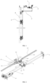
- a multi-point locking mechanism for a door system comprises a driving mechanism, wherein the driving mechanism is able to rotate by an angle under the restriction of a guide rail when door leaves are about to be closed or opened, to partially lock or unlock a door system; and during rotation, the driving mechanism drives a transmission mechanism to move to drive a side locking assembly to lock or unlock the door system, such that multi-point restriction of the side face of the door system is realized.
- the transmission mechanism comprises a transmission shaft, a transmission fork is fixed on the transmission shaft, the transmission shaft is connected to one end of a first rotating arm, the other end of the first rotating arm is connected to one end of a first connecting rod, and the other end of the first connecting rod is connected to one end of a second rotating arm;
- a mounting block is disposed on the transmission shaft, a limiting pillar is disposed on the mounting block, and the transmission fork contacts the limiting pillar when restored;
- the side locking assembly comprises a lock body, a rotatable lock fork is disposed in the lock body, a torsion spring is disposed in the lock fork, the lock fork is initially in a restored state under the action of the torsion spring, and a second wheel is disposed at a rear end of the lock fork;
- a rotating shaft is disposed in the lock body, an inner swing arm is mounted on the rotating shaft and is driven by the rotating shaft to rotate, and when the inner swing arm rotates in position, a front end of the
- the driving mechanism comprises a driving motor, the driving motor drives a lead screw to rotate, the lead screw is sleeved with a lead screw nut, one end of the lead screw nut is rotatably connected to one end of a transmission frame through a first hinge pin, the other end of the transmission frame is articulated with one end of a transmission plate, a wheel is disposed on the transmission plate and is movably connected to a guide rail, the guide rail comprises a linear section, a curved section and a grooved section, the linear section, the curved section and the grooved section are connected in sequence, and the lead screw nut is matched with the transmission fork.
- multiple side locking assemblies are arranged, a tail end of the rotating shaft of each of the multiple side locking assemblies is connected to the driving shaft of the next side locking assembly through a universal joint, and the driving shaft of the first side locking assembly is connected to the second rotating arm.
- the multi-point locking mechanism further comprises an unlocking mechanism
- the unlocking mechanism comprises an unlocking handle
- the unlocking handle is rotatably connected to the transmission mechanism and is used for driving the transmission mechanism to move reversely
- an unlocking elastic element is disposed on the transmission mechanism and is used for restoring the unlocking handle.
- the multi-point locking mechanism further comprises a transmission fork position holding mechanism
- the transmission fork position holding mechanism comprises a mounting plate
- stop links are movably connected to the mounting plate and are sleeved with elastic elements
- rotating blocks are disposed on the transmission shaft, a free end of each of the rotating blocks is rotatably connected to one end of the corresponding stop link, and the elastic elements are used for maintaining a force of the rotating blocks in the rotation direction.
- the driving mechanism comprises a driving motor, the driving motor drives a lead screw to rotate, the lead screw is sleeved with a lead screw nut, one end of the lead screw nut is connected to a first hinge pin, a wheel is disposed at the other end of the lead screw nut and is movably connected to a guide rail, the guide rail comprises a linear section and a grooved section, and the linear section and the grooved section are connected in sequence; and the first hinge pin drives the transmission mechanism to move.
- the transmission mechanism comprises a transmission shaft, a transmission fork is fixed on the transmission shaft and is matched with the first hinge pin, the transmission shaft is connected to the middle of a first rotating arm, and one end of the first rotating arm is connected to a first connecting rod through a universal joint; a limiting pillar is disposed on a shaft mounting plate at one end of the transmission shaft, and the first rotating arm contacts the limiting pillar when rotating; and the side locking assembly comprises a driving shaft, one end of the driving shaft is connected to the first connecting rod through a universal joint, and a bolt is disposed on the driving shaft.
- multiple bolts are disposed on the driving shaft.
- the multi-point locking mechanism further comprises an unlocking mechanism
- the unlocking mechanism comprises an unlocking handle
- the unlocking handle is disposed on the driving shaft and drives the bolts on the driving shaft to move upwards or downwards in a vertical direction.
- the multi-point locking mechanism further comprises a transmission fork position holding mechanism
- the transmission fork position holding mechanism comprises a mounting plate, a stop link is movably connected to the mounting plate and is sleeved with an elastic element, and the stop link is rotatably connected to the other end of the first rotating arm.
- the multi-point locking mechanism for a door system has the following beneficial effects: the top of door leaves can be locked by means of the driving mechanism which can pass a dead point and is restrained by the grooved section of the guide rail; in addition, the side face of the door leaves can be locked by means of the restriction effect of the side locking assembly on lock pillars or latches; moreover, multiple side locking assemblies can be mounted on the side face of the door leaves to realize multi-point locking of the side face of the door leaves.
- the side locking assembly on the side face of the door system is controlled to lock or unlock the door system by means of the movement of the driving mechanism in the locking or unlocking process, such that multi-point restriction of the door system is realized, the locking effect is good; and the locking or unlocking operation of the side locking assembly is performed after the door leaves are closed or before the door leaves are opened, so motion interference is avoided, and locking is reliable.
- the multi-point locking mechanism is simple in structure and easy to maintain, and occupies a small space, the side locking assembly can be a universal joint, and multiple locking assemblies can be connected in series to one side of the door system to satisfy different locking strength requirements.
- the multi-point locking mechanism is suitable for flat doors, curved doors, single doors, double doors, sliding-plug doors, sliding doors and other doors, thus being good in universality.
- a multi-point locking mechanism for a door system comprises a driving mechanism, wherein the driving mechanism is able to rotate by an angle under the restriction of a guide rail when door leaves are about to be closed or opened, to partially lock or unlock a door system; and during rotation, the driving mechanism drives a transmission mechanism to move to drive a side locking assembly to lock or unlock the door system, such that multi-point restriction of the side face of the door system is realized.
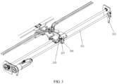
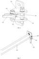
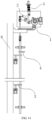
- a driving mechanism 1 comprises a driving motor 101, wherein the driving motor 101 is connected to one end of a lead screw 102 through a transmission belt 102, the lead screw 102 is sleeved with a lead screw nut 103, one end of the lead screw nut 103 is rotatably connected to one end of a transmission frame 104 through a first hinge pin 105, the other end of the transmission frame 104 is articulated with one end of a transmission plate 106, the other end of the transmission plate 106 is connected to a door-linked frame 107, and the door-linked frame 107 is connected to door leaves 6.
- a wheel 108 is disposed on the transmission plate 106 and is movably connected to a guide rail 109, the guide rail 109 comprises a linear section 1091, a curved section 1092 and a grooved section 1093, and the linear section 1091, the curved section 1092 and the grooved section 1093 are connected in sequence; when the wheel 108 moves to the tail end of the grooved section 1093, the door leaves 6 are closed in position, and the transmission frame 104 rotates to retract; and when the wheel 108 sequentially moves through the curved section 1092 and the linear section 1091 from the tail end of the grooved section 1093, the door leaves are opened gradually, and the transmission frame 104 rotates to stretch out.
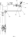
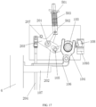
- a transmission mechanism 2 comprises a transmission shaft 201, and a transmission fork 202 is fixed on the transmission shaft 201 and is matched with one end of the first hinge pin 105; when the first hinge pin 105 rotates to retract with the lead screw nut 103, the transmission fork 202 rotates downwards with the first hinge pin 105; and when the first hinge pin 105 rotates to stretch out with the lead screw nut 103, the transmission fork 202 rotates upwards with the first hinge pin 105 until it is separated from the first hinge pin 105.
- the transmission shaft 202 is connected to one end of a first rotating arm 203, the other end of the first rotating arm 203 is connected to one end of a first connecting rod 204, and the other end of the first connecting rod 204 is connected to one end of a second rotating arm 205.
- a mounting block 206 is disposed on the transmission shaft 201, a limiting pillar 207 is disposed on the mounting block 206, and the transmission fork 202 contacts the limiting pillar 207 when rotating upwards.
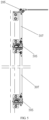
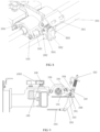
- a side locking assembly 3 comprises a lock body 301, wherein a rotatable lock fork 302 is disposed in the lock body 301, a torsion spring 303 is disposed in the lock fork 302, the lock fork 302 is initially in a restored state under the action of the torsion spring 303, and a second wheel 304 is disposed at a rear end of the lock fork 302; a rotating shaft 305 is disposed in the lock body 302, an inner swing arm 306 is mounted on the rotating shaft 305 and is driven by the rotating shaft 305 to rotate, and when the inner swing arm 306 rotates in position, a front end of the inner swing arm 306 contacts the second wheel 304; and one end of the rotating shaft 305 is connected to one end of the driving shaft 307 through a universal joint, and the other end of the driving shaft 307 is connected to the other end of the second rotating arm 205.
- an unlocking mechanism 4 comprises an unlocking handle 401, wherein the unlocking handle 401 is rotatably connected to the transmission mechanism and is used for driving the transmission mechanism to rotate reversely, and an unlocking elastic element is disposed on the transmission mechanism and is used for restoring the transmission mechanism after the transmission mechanism rotates reversely.
- the unlocking handle 401 may be mounted on any one part of the transmission mechanism, such as the transmission shaft, the first rotating arm or the first connecting rod, as long as the unlocking handle 401 can drive the part to move reversely to allow the driving shaft to rotate to drive the side unlocking assembly to unlock the door leaves.
- the unlocking elastic element 402 such as a torsion spring is disposed around the transmission shaft 201, and under the action of the torsion spring, the unlocking handle can be restored after being released.
- a transmission fork position holding mechanism 5 comprises a mounting plate 501, wherein stop links 502 are movably connected to the mounting plate 501, elastic elements 503 such as pressure springs are disposed around the stop links 502, rotating blocks 504 are disposed around the transmission shaft 201, and a free end of each of the rotating blocks 504 is rotatably connected to one end of the corresponding stop link 502.
- the rotating blocks 504 are driven to rotate to drive the stop links 502 to rotate; and when the transmission fork 202 cannot continue to rotate upwards under the action of the limiting pillar 207, the elastic elements 503 maintain the upward rotation force of the rotating blocks 503 through the stop links 502 to keep the transmission fork 202 static.
- the rotating blocks 504 are driven to rotate to drive the stop links 502 to rotate; when the rotation point of the transmission fork 202 exceeds the maximum rotation position of the transmission plate 106 and the transmission frame 105 which are articulated together, the transmission fork 202 stops rotating downwards, and the elastic elements 503 maintain the downward rotation force of the rotating blocks 504 through the stop links 502 to keep the transmission fork 202 static.
- the motor drives the lead screw nut on the lead screw to move towards the middle, the wheel moves to the curved section from the linear section, under the restriction of the curved section, the lead screw nut drives the transmission frame to move towards the middle and rotate downwards along the lead screw at the same time, as shown in FIG 9 , until the first hinge pin contacts the transmission fork and drives the transmission fork to rotate downward synchronously, then the transmission fork drives the transmission shaft to rotate and drives the rotating blocks to rotate, and the rotating blocks drive the stop links to rotate.
- the lead screw nut stops rotating, the first hinge pin and the transmission fork also stop rotating; because the transmission shaft and the transmission frame are articulated, the transmission frame and the lead screw nut are articulated through the first hinge pin, the positions of the first hinge pin and the transmission fork are lower than the connecting line between the hinge point of the transmission plate and the transmission frame and the central point of the lead screw (that is, the first hinge pin and the transmission fork have passed the dead point), and the transmission fork is driven by the first hinge pin to the final position, the first hinge pin and the transmission fork will be locked below the dead point under the action of the transmission fork position holding mechanism, such that an outward pulling force and an upward moving force transmitted from the door leaves through the transmission frame can be effectively cut off, and the door leaves are locked.
- the wheel stops at the tail end of the grooved section, and the left and right sides of the wheel are restrained by the grooved section, such that the door leaves are locked in the direction of the lead screw.
- lock pillars 601 on side faces of the door leaves 6 contact the lock fork and drive the lock fork to rotate, and the second wheel rotates at the same time until the door leaves are closed, as shown in FIG 12 , such that the lock pillars and the lock fork are locked, and the second wheel rotates in position.
- the transmission shaft rotates with the transmission fork and sequentially drives the first rotating arm, the first connecting rod and the second rotating arm to rotate, the second rotating arm drives the transmission shaft to rotate, and the driving shaft drives the rotating shaft to rotate through the universal joint, the rotating shaft drives the inner swing arm to rotate until the inner swing arm contacts the second wheel, such that the lock fork and the lock pillars are locked.
- multiple side locking assemblies may be connected in series through universal joints to realize multi-point locking of the door leaves.
- the driving motor drives the lead screw nut on the lead screw to move, under the restriction of the grooved section, the lead screw nut drives the transmission frame to rotate upwards and also drives the first hinge pin and the transmission fork to rotate upwards, such that the door leaves are unlocked for the first time; because the transmission plate and the transmission frame are articulated, the transmission plate can be kept static, as shown in FIG 9 , until the transmission fork stops at the position of the limiting pillar, and the first hinge pin is separated from the transmission fork, such that the door leaves are unlocked for the second time.
- the transmission fork drives the transmission shaft to rotate, and the second wheel, restrained by the inner swing arm, at the rear end of the lock fork is released through parts such as the first rotating arm, such that the side locking assembly is unlocked.
- the transmission fork is kept static under the actin of the transmission fork position holding mechanism.
- the lead screw nut continues to rotate upwards; on the curved section, the transmission frame rotates and drives the door leaves to be opened towards two sides through the transmission plate and the door-linked frame until the wheel moves out of the curved section, and the lead screw nut stops rotating; and when the wheel moves on the linear section, the lead screw nut moves horizontally until the door leaves are completely opened.
- the unlocking handle is rotated manually to drive the transmission shaft to rotate, the transmission shaft sequentially drives the first rotating arm, the first connecting rod and the second rotating arm to rotate, the second rotating arm drives the driving shaft to rotate, the driving shaft drives the rotating shaft to rotate, the rotating shaft drives the inner swing arm to rotate to be separated from the second wheel, such that the lock fork is released.
- the transmission shaft drives the transmission fork to enable the transmission frame to rotate upwards to remove the locking state on the dead point, and because the transmission fork which rotates synchronously on the transmission shaft can only cause the lead screw nut and the transmission frame to rotate and will not cause the transmission plate to move, the door leaves can move without being affected.
- the door leaves can be manually opened outwards, and the unlocking handle is restored under the action of the torsion spring.
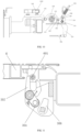
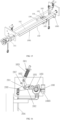
- a driving mechanism 1 comprises a driving motor 101, wherein the driving motor 101 is connected to one end of a lead screw 102, the lead screw 102 is sleeved with a lead screw nut 103, one end of the lead screw nut 103 is connected to a first hinge pin 105, a front end of a transmission frame 104 is rotatably clamped on the lead screw nut 103, a rear end of the transmission frame 104 is articulated with one end of a transmission plate 106, and the other end of the transmission plate 106 is connected to a door-linked frame 106, the door-linked frame 107 is connected to door leaves 6.
- a wheel 108 is disposed at the other end of the lead screw nut and is movably connected to a guide rail 109, the guide rail comprises a linear section 1091 and a grooved section 1093, and the linear section 1091 and the grooved section 1093 are connected in sequence.
- the wheel 108 moves to the grooved section 1093, one end of the wheel 108 of the lead screw nut 103 rotates downwards until the wheel 108 is clamped at a tail end of the grooved section 1093.
- a transmission mechanism 2 comprises a transmission shaft 201, wherein a transmission fork 202 is fixed on the transmission shaft 201; before the lead screw nut 103 enters the grooved section 1093, the first hinge pin 105 contacts the transmission fork 202; when the first hinge pin 105 moves from the top end of the grooved section 1093 to the bottom end of the grooved section 1093 with the lead screw nut 103, the transmission fork 202 rotates upwards with the first hinge pin 105; when the first hinge pin 105 moves from the bottom end of the grooved section 1093 to the top end of the grooved section 1093 with the lead screw nut 103, the transmission fork 202 rotates downwards with the first hinge pin 105, then the lead screw nut 103 moves out of the grooved section 1093 and enters the linear section 1091, and at this moment, the first hinge pin 105 is separated from the transmission fork 202.
- the transmission shaft 201 is connected to the middle of a first rotating arm 203, and one end of the first rotating arm 203 is connected to a first connecting rod 204 through a universal joint; and a limiting pillar 207 is disposed on a mounting plate at one end of the transmission shaft 201, and the first rotating arm 203 contacts the limiting pillar 207 when rotating towards one side.
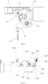
- a side locking assembly 3 comprises a driving shaft 307, wherein one end of the driving shaft 307 is connected to the first connecting rod 204 through a universal joint, bolts 308 are disposed on the driving shaft 307, and the first rotating arm 203 drives the bolts 308 on the driving shaft 307 to move upwards or downwards in the vertical direction through the first connecting rod 204.
- An unlocking mechanism 4 comprises an unlocking handle 401, wherein the unlocking handle 401 is disposed on the driving shaft 307 and drives the bolts 308 on the driving shaft 307 to move upwards or downwards in the vertical direction.
- a transmission fork position holding mechanism 5 comprises a mounting plate 501, wherein a stop link 502 is movably connected to the mounting plate 501, an elastic element 503 such as a pressure spring is disposed around the stop link 502, and the stop link 502 is rotatably connected to the other end of the first rotating arm 203.
- the transmission shaft 201 drives the first rotating arm 203 to rotate, the first rotating arm 203 drives the stop link 502 to rotate; at this moment, the first rotating arm 203 is limited by the limiting pillar 207 and the transmission fork 202 is limited by the wheel, restrained by the grooved section 1093, on the lead screw nut 103, so the first rotating arm 203 cannot continue to rotate in this direction; meanwhile, the elastic element 503 maintains the rotation force of the first rotating arm 203 in this direction through the stop link 502 to keep the transmission fork 202 static, and the bolts 308 on the driving shaft 307 will not move downwards.
- the transmission shaft 201 drives the first rotating arm 203 to rotate, the first rotating arm 203 drives the stop link 502 to rotate, at this moment, the first rotating arm 203 is limited by the limiting pillar 207 and cannot continue to rotate in this direction, the elastic element 503 maintains the rotation force of the first rotating arm 203 in this direction through the stop link 502 to keep the transmission fork 202 static, and the bolts 308 on the driving shaft 307 will not move upwards.
- the driving motor drives the lead screw nut on the lead screw to move towards the tail end of the guide rail, the wheel moves into the grooved section from the linear section, the lead screw nut drives the transmission frame, the transmission plate, the door-linked frame and the door leaves to move, and the door leaves are closed under the restriction of the door-sliding guide rail.
- the first hinge pin contacts the transmission fork; then, the wheel starts to rotate downwards under the restriction of the grooved section and drives the transmission fork to rotate upwards, the transmission fork drives the transmission shaft to rotate, the transmission shaft drives the first rotating arm to rotate until the wheel rotates to the bottom of the grooved section, and at this moment, the left and right sides of the wheel are restrained by the grooved section, such that the door leaves are locked in the direction of the lead screw.
- the first rotating arm drives the first connecting rod to move downwards in the vertical direction
- the first connecting rod drives the bolts on the driving shaft to move downwards; at this moment, because the door leaves have closed, latches disposed on side faces of the door leaves are completely matched with bolt guide plates 602 mounted on a vehicle, and the bolts are inserted into lock holes of the latches through the bolt guide plates, such that the side faces of the door leaves are locked.
- multiple bolts are connected in series to the first connecting rod, and connecting rod guide plates are mounted on the vehicle, such that the first connecting rod can move upwards or downwards more stably, and multi-point locking of the side faces of the door leaves is realized.
- the elastic element maintains the rotation force of the first rotating arm in this direction through the stop link to keep the transmission fork static, and the bolts on the driving shafts will not move downwards.
- the driving motor drives the lead screw nut on the lead screw to move, under the restriction of the grooved section, the wheel on the lead screw nut rotates upwards, as shown in FIG 17 , to drive the first hinge pin and the transmission fork to rotate downwards, and when the wheel moves from the bottom of the grooved section to the top of the grooved section, the door leaves are unlocked for the first time.
- the transmission fork drives the transmission shaft to rotate
- the transmission shaft drives the first rotating arm to rotate
- the first rotating arm drives the first connecting rod to move upwards in the vertical direction
- the first connecting rod drives the bolts to move upwards to be separated from the latches on the side face of the door leaves and the bolt guide plates on the vehicle, such that the side faces of the door leaves are unlocked.
- the lead screw nut moves horizontally along the linear section to be separated from the transmission fork, and drives the door leaves to be opened under the restriction of the door-sliding guide rail.
- the other end of the first rotating arm drives the stop link to rotate, and when the first rotating arm cannot continue to rotate in this direction under the action of the limiting pillar, the elastic element maintains the rotation force of the first rotating arm in this direction through the stop link to keep the transmission fork static, and the bolts on the driving shaft will not move upwards.
- the unlocking handle can be lifted manually and drive the transmission shaft to move upwards, the first connecting rod drives the bolts to move upwards to be separated from the latches on the side faces of the door leaves and the bolt guide plates on the vehicle, such that the side faces of the door leaves are unlocked; and because the rotation of the first rotating arm can only cause the lead screw nut to rotate and will not cause the lead screw nut to move horizontally, the door leaves can move without being affected.
- the door leaves can be manually opened outwards.
Landscapes
- Engineering & Computer Science (AREA)
- Mechanical Engineering (AREA)
- Life Sciences & Earth Sciences (AREA)
- Geology (AREA)
- Mining & Mineral Resources (AREA)
- Physics & Mathematics (AREA)
- Environmental & Geological Engineering (AREA)
- Fluid Mechanics (AREA)
- General Life Sciences & Earth Sciences (AREA)
- Geochemistry & Mineralogy (AREA)
- Power-Operated Mechanisms For Wings (AREA)
- Lock And Its Accessories (AREA)
Applications Claiming Priority (2)
| Application Number | Priority Date | Filing Date | Title |
|---|---|---|---|
| CN202110351088.1A CN112855046B (zh) | 2021-03-31 | 2021-03-31 | 一种门系统多点锁闭机构 |
| PCT/CN2021/095713 WO2022205591A1 (zh) | 2021-03-31 | 2021-05-25 | 一种门系统多点锁闭机构 |
Publications (2)
| Publication Number | Publication Date |
|---|---|
| EP4317644A1 true EP4317644A1 (de) | 2024-02-07 |
| EP4317644A4 EP4317644A4 (de) | 2024-08-21 |
Family
ID=75991922
Family Applications (1)
| Application Number | Title | Priority Date | Filing Date |
|---|---|---|---|
| EP21934242.5A Pending EP4317644A4 (de) | 2021-03-31 | 2021-05-25 | Mehrpunktverriegelungsmechanismus für türsystem |
Country Status (3)
| Country | Link |
|---|---|
| EP (1) | EP4317644A4 (de) |
| CN (1) | CN112855046B (de) |
| WO (1) | WO2022205591A1 (de) |
Families Citing this family (13)
| Publication number | Priority date | Publication date | Assignee | Title |
|---|---|---|---|---|
| CN114382359B (zh) * | 2022-01-14 | 2025-12-23 | 欧特美交通科技股份有限公司 | 一种轨道车辆及其门扇下部锁闭装置 |
| CN218177038U (zh) * | 2022-06-24 | 2022-12-30 | 国创移动能源创新中心(江苏)有限公司 | 一种侧滑门 |
| CN115949318B (zh) * | 2022-08-10 | 2025-06-27 | 吉林省泰浩轨道客车装备有限公司 | 一种双开塞拉及闭锁机构及应用其的塞拉门 |
| CN115653436B (zh) * | 2022-10-31 | 2025-09-02 | 南京康尼机电股份有限公司 | 一种多点同步锁闭的塞拉门系统 |
| CN115874891B (zh) * | 2022-11-25 | 2025-12-12 | 广州通达汽车电气股份有限公司 | 塞拉门及车辆 |
| CN116220478B (zh) * | 2023-02-28 | 2024-06-11 | 南京康尼机电股份有限公司 | 微型电动自解锁锁闭装置 |
| TWI836921B (zh) * | 2023-03-02 | 2024-03-21 | 大陸商上海銘唯五金有限公司 | 逃生門鎖之電控系統連接傳動開鎖機構及其多選擇性套件 |
| CN116575806B (zh) * | 2023-04-19 | 2025-07-01 | 南京康尼机电股份有限公司 | 一种用于轨道车辆门系统的无源锁闭装置及双锁闭结构 |
| CN116378536B (zh) * | 2023-05-24 | 2025-11-25 | 中国船舶集团有限公司第七〇四研究所 | 一种双向自动开门装置及其运行方法 |
| CN116971676B (zh) * | 2023-07-12 | 2025-08-12 | 南京康尼机电股份有限公司 | 一种挡销随动约束装置、门系统及车辆 |
| CN118082902B (zh) * | 2024-04-16 | 2024-08-09 | 今创集团股份有限公司 | 一种列车逃生系统释放回收装置 |
| CN118309320B (zh) * | 2024-06-11 | 2024-12-06 | 南京晨光东螺波纹管有限公司 | 一种双密封门系统 |
| CN119145721B (zh) * | 2024-09-24 | 2025-09-09 | 南京康尼机电股份有限公司 | 一种驱动锁闭一体化的大开度塞拉门系统 |
Family Cites Families (15)
| Publication number | Priority date | Publication date | Assignee | Title |
|---|---|---|---|---|
| FR2534617B1 (fr) * | 1982-10-18 | 1986-06-13 | Vachette Sa | Serrure de porte, notamment pour vehicule automobile |
| US5906403A (en) * | 1997-05-12 | 1999-05-25 | Truth Hardware Corporation | Multipoint lock for sliding patio door |
| US6712406B2 (en) * | 2002-08-28 | 2004-03-30 | Westubggiyse Aur Brake Technologies Corporation | Lock latch mechanism for transit vehicle door system |
| CN201344253Y (zh) * | 2008-12-24 | 2009-11-11 | 南京康尼机电新技术有限公司 | 万向同步传动锁闭装置 |
| CN101666242B (zh) * | 2009-09-24 | 2012-11-28 | 中国人民解放军总参谋部工程兵第四设计研究院 | 地铁区间液压立转式防淹防护密闭隔断门 |
| CN204081737U (zh) * | 2014-09-03 | 2015-01-07 | 南京康尼机电股份有限公司 | 一种用于门系统的过死点锁闭装置 |
| CN204343913U (zh) * | 2014-12-10 | 2015-05-20 | 北京凯必盛自动门技术有限公司 | 一种折叠式自动入户门 |
| US11066850B2 (en) * | 2017-07-25 | 2021-07-20 | Amesbury Group, Inc | Access handle for sliding doors |
| GB2568730B (en) * | 2017-11-24 | 2022-07-20 | Mighton Products Ltd | Door lock assembly |
| EP3792131B1 (de) * | 2018-05-11 | 2023-04-26 | JC Disseny Ingenieria i Aplicacions S.L. | Vorrichtung zum öffnen und schliessen von türen öffentlicher verkehrsmittel |
| CN209976248U (zh) * | 2019-01-17 | 2020-01-21 | 南京康尼机电股份有限公司 | 一种动车组车门系统的电动锁装置 |
| CN211166377U (zh) * | 2019-12-03 | 2020-08-04 | 上海汽车集团股份有限公司 | 一种汽车及其塞拉门传动机构 |
| CN111810004B (zh) * | 2020-07-09 | 2025-03-18 | 南京康尼机电股份有限公司 | 一种用于公交车辆电动塞拉门 |
| CN112901002B (zh) * | 2021-03-31 | 2025-04-04 | 南京康尼机电股份有限公司 | 一种双开塞拉门系统 |
| CN214944081U (zh) * | 2021-03-31 | 2021-11-30 | 南京康尼机电股份有限公司 | 一种门系统多点锁闭机构 |
-
2021
- 2021-03-31 CN CN202110351088.1A patent/CN112855046B/zh active Active
- 2021-05-25 WO PCT/CN2021/095713 patent/WO2022205591A1/zh not_active Ceased
- 2021-05-25 EP EP21934242.5A patent/EP4317644A4/de active Pending
Also Published As
| Publication number | Publication date |
|---|---|
| WO2022205591A1 (zh) | 2022-10-06 |
| EP4317644A4 (de) | 2024-08-21 |
| CN112855046A (zh) | 2021-05-28 |
| CN112855046B (zh) | 2024-11-19 |
Similar Documents
| Publication | Publication Date | Title |
|---|---|---|
| EP4317644A1 (de) | Mehrpunktverriegelungsmechanismus für türsystem | |
| CN112901002B (zh) | 一种双开塞拉门系统 | |
| US5142823A (en) | Swinging-sliding door for vehicles | |
| US10994752B2 (en) | Lock mechanism for improved door panel seal | |
| CN104773637A (zh) | 带轿门锁的异步门刀、电梯门机及轿门系统 | |
| CN107605307B (zh) | 开闭机构、锁定机构及前部自锁装置 | |
| CN214944081U (zh) | 一种门系统多点锁闭机构 | |
| US11359429B2 (en) | System for closing and opening at least one leaf of an inward swinging door | |
| CN111038535B (zh) | 锁闭装置以及漏斗车 | |
| CN216277444U (zh) | 一种双开塞拉门系统 | |
| CN111648679A (zh) | 一种城市轨道客车塞拉门的锁闭装置 | |
| CN116238681A (zh) | 一种舱门上位锁机构装置 | |
| CN113173185B (zh) | 一种锁定装置及前端开闭机构 | |
| CN110965870B (zh) | 一种非危险舱门闩提升机构 | |
| CN107720506B (zh) | 一体式轿门锁异步门刀装置 | |
| CN217553958U (zh) | 一种新能源汽车电池回收转运机构 | |
| CN113233295B (zh) | 轿门开闭控制机构、厅门开闭控制机构及门系统 | |
| US10724278B2 (en) | Secondary retention device for bi-parting doors | |
| CN112227879B (zh) | 塞拉门总成 | |
| CN115653436B (zh) | 一种多点同步锁闭的塞拉门系统 | |
| CN113173186A (zh) | 一种轨道车辆用前端开闭机构 | |
| CN219528717U (zh) | 一种可伸缩的锁具 | |
| CN218967183U (zh) | 一种周向多点挂载抛放装置 | |
| CN217864118U (zh) | 一种底门控制系统 | |
| CN218912625U (zh) | 一种铁路机车滑门机构 |
Legal Events
| Date | Code | Title | Description |
|---|---|---|---|
| STAA | Information on the status of an ep patent application or granted ep patent |
Free format text: STATUS: THE INTERNATIONAL PUBLICATION HAS BEEN MADE |
|
| PUAI | Public reference made under article 153(3) epc to a published international application that has entered the european phase |
Free format text: ORIGINAL CODE: 0009012 |
|
| STAA | Information on the status of an ep patent application or granted ep patent |
Free format text: STATUS: REQUEST FOR EXAMINATION WAS MADE |
|
| 17P | Request for examination filed |
Effective date: 20230921 |
|
| AK | Designated contracting states |
Kind code of ref document: A1 Designated state(s): AL AT BE BG CH CY CZ DE DK EE ES FI FR GB GR HR HU IE IS IT LI LT LU LV MC MK MT NL NO PL PT RO RS SE SI SK SM TR |
|
| DAV | Request for validation of the european patent (deleted) | ||
| DAX | Request for extension of the european patent (deleted) | ||
| A4 | Supplementary search report drawn up and despatched |
Effective date: 20240724 |
|
| RIC1 | Information provided on ipc code assigned before grant |
Ipc: E05B 83/36 20140101ALI20240718BHEP Ipc: E05D 15/10 20060101ALI20240718BHEP Ipc: E05F 15/655 20150101ALI20240718BHEP Ipc: E05F 15/652 20150101AFI20240718BHEP |
|
| STAA | Information on the status of an ep patent application or granted ep patent |
Free format text: STATUS: EXAMINATION IS IN PROGRESS |
|
| 17Q | First examination report despatched |
Effective date: 20250703 |