EP4317657A1 - Variable leitschaufelanordnung für gasturbinenmotor - Google Patents
Variable leitschaufelanordnung für gasturbinenmotor Download PDFInfo
- Publication number
- EP4317657A1 EP4317657A1 EP23189310.8A EP23189310A EP4317657A1 EP 4317657 A1 EP4317657 A1 EP 4317657A1 EP 23189310 A EP23189310 A EP 23189310A EP 4317657 A1 EP4317657 A1 EP 4317657A1
- Authority
- EP
- European Patent Office
- Prior art keywords
- vane
- ramp
- outer radial
- slot
- collar
- Prior art date
- Legal status (The legal status is an assumption and is not a legal conclusion. Google has not performed a legal analysis and makes no representation as to the accuracy of the status listed.)
- Pending
Links
Images


Classifications
-
- F—MECHANICAL ENGINEERING; LIGHTING; HEATING; WEAPONS; BLASTING
- F01—MACHINES OR ENGINES IN GENERAL; ENGINE PLANTS IN GENERAL; STEAM ENGINES
- F01D—NON-POSITIVE DISPLACEMENT MACHINES OR ENGINES, e.g. STEAM TURBINES
- F01D17/00—Regulating or controlling by varying flow
- F01D17/10—Final actuators
- F01D17/12—Final actuators arranged in stator parts
- F01D17/14—Final actuators arranged in stator parts varying effective cross-sectional area of nozzles or guide conduits
- F01D17/16—Final actuators arranged in stator parts varying effective cross-sectional area of nozzles or guide conduits by means of nozzle vanes
- F01D17/167—Final actuators arranged in stator parts varying effective cross-sectional area of nozzles or guide conduits by means of nozzle vanes of vanes moving in translation
-
- F—MECHANICAL ENGINEERING; LIGHTING; HEATING; WEAPONS; BLASTING
- F01—MACHINES OR ENGINES IN GENERAL; ENGINE PLANTS IN GENERAL; STEAM ENGINES
- F01D—NON-POSITIVE DISPLACEMENT MACHINES OR ENGINES, e.g. STEAM TURBINES
- F01D17/00—Regulating or controlling by varying flow
- F01D17/10—Final actuators
- F01D17/12—Final actuators arranged in stator parts
- F01D17/14—Final actuators arranged in stator parts varying effective cross-sectional area of nozzles or guide conduits
- F01D17/16—Final actuators arranged in stator parts varying effective cross-sectional area of nozzles or guide conduits by means of nozzle vanes
- F01D17/162—Final actuators arranged in stator parts varying effective cross-sectional area of nozzles or guide conduits by means of nozzle vanes for axial flow, i.e. the vanes turning around axes which are essentially perpendicular to the rotor centre line
-
- F—MECHANICAL ENGINEERING; LIGHTING; HEATING; WEAPONS; BLASTING
- F01—MACHINES OR ENGINES IN GENERAL; ENGINE PLANTS IN GENERAL; STEAM ENGINES
- F01D—NON-POSITIVE DISPLACEMENT MACHINES OR ENGINES, e.g. STEAM TURBINES
- F01D9/00—Stators
- F01D9/02—Nozzles; Nozzle boxes; Stator blades; Guide conduits, e.g. individual nozzles
- F01D9/04—Nozzles; Nozzle boxes; Stator blades; Guide conduits, e.g. individual nozzles forming ring or sector
- F01D9/041—Nozzles; Nozzle boxes; Stator blades; Guide conduits, e.g. individual nozzles forming ring or sector using blades
-
- F—MECHANICAL ENGINEERING; LIGHTING; HEATING; WEAPONS; BLASTING
- F04—POSITIVE - DISPLACEMENT MACHINES FOR LIQUIDS; PUMPS FOR LIQUIDS OR ELASTIC FLUIDS
- F04D—NON-POSITIVE-DISPLACEMENT PUMPS
- F04D19/00—Axial-flow pumps
- F04D19/02—Multi-stage pumps
-
- F—MECHANICAL ENGINEERING; LIGHTING; HEATING; WEAPONS; BLASTING
- F04—POSITIVE - DISPLACEMENT MACHINES FOR LIQUIDS; PUMPS FOR LIQUIDS OR ELASTIC FLUIDS
- F04D—NON-POSITIVE-DISPLACEMENT PUMPS
- F04D29/00—Details, component parts, or accessories
- F04D29/40—Casings; Connections of working fluid
- F04D29/52—Casings; Connections of working fluid for axial pumps
- F04D29/54—Fluid-guiding means, e.g. diffusers
- F04D29/56—Fluid-guiding means, e.g. diffusers adjustable
- F04D29/563—Fluid-guiding means, e.g. diffusers adjustable specially adapted for elastic fluid pumps
-
- F—MECHANICAL ENGINEERING; LIGHTING; HEATING; WEAPONS; BLASTING
- F05—INDEXING SCHEMES RELATING TO ENGINES OR PUMPS IN VARIOUS SUBCLASSES OF CLASSES F01-F04
- F05D—INDEXING SCHEME FOR ASPECTS RELATING TO NON-POSITIVE-DISPLACEMENT MACHINES OR ENGINES, GAS-TURBINES OR JET-PROPULSION PLANTS
- F05D2240/00—Components
- F05D2240/10—Stators
- F05D2240/11—Shroud seal segments
-
- F—MECHANICAL ENGINEERING; LIGHTING; HEATING; WEAPONS; BLASTING
- F05—INDEXING SCHEMES RELATING TO ENGINES OR PUMPS IN VARIOUS SUBCLASSES OF CLASSES F01-F04
- F05D—INDEXING SCHEME FOR ASPECTS RELATING TO NON-POSITIVE-DISPLACEMENT MACHINES OR ENGINES, GAS-TURBINES OR JET-PROPULSION PLANTS
- F05D2260/00—Function
- F05D2260/30—Retaining components in desired mutual position
- F05D2260/36—Retaining components in desired mutual position by a form fit connection, e.g. by interlocking
-
- F—MECHANICAL ENGINEERING; LIGHTING; HEATING; WEAPONS; BLASTING
- F05—INDEXING SCHEMES RELATING TO ENGINES OR PUMPS IN VARIOUS SUBCLASSES OF CLASSES F01-F04
- F05D—INDEXING SCHEME FOR ASPECTS RELATING TO NON-POSITIVE-DISPLACEMENT MACHINES OR ENGINES, GAS-TURBINES OR JET-PROPULSION PLANTS
- F05D2260/00—Function
- F05D2260/50—Kinematic linkage, i.e. transmission of position
-
- F—MECHANICAL ENGINEERING; LIGHTING; HEATING; WEAPONS; BLASTING
- F05—INDEXING SCHEMES RELATING TO ENGINES OR PUMPS IN VARIOUS SUBCLASSES OF CLASSES F01-F04
- F05D—INDEXING SCHEME FOR ASPECTS RELATING TO NON-POSITIVE-DISPLACEMENT MACHINES OR ENGINES, GAS-TURBINES OR JET-PROPULSION PLANTS
- F05D2260/00—Function
- F05D2260/50—Kinematic linkage, i.e. transmission of position
- F05D2260/56—Kinematic linkage, i.e. transmission of position using cams or eccentrics
Definitions
- the present invention relates to gas turbine engines in general, and to variable guide vane assemblies for use in a gas turbine engine in particular.
- VSVs Variable guide vanes
- variable vane are prone to leakage at the interfaces between the rotatable vanes and the surrounding static flow assemblies; i.e., between the outer radial edge surface of the vane and the inner circumferential surface of the shroud and between the inner radial edge surface of the vane and the outer radial surface of the hub.
- Variable vane devices are typically designed to minimize such vane/shroud clearances and vane/hub clearances, while avoiding contact between the vane edge surfaces and the shroud and hub.
- the clearances vary as a function of vane rotational position. Such leakage may lower engine efficiency and create undesirable airflow anomalies.
- variable guide vane system that is an improvement over the currently available variable guide vanes systems.
- variable guide vane assembly for a gas turbine engine stator having a shroud and a hub.
- the shroud and hub extend circumferentially.
- the shroud is disposed radially outside of the hub, and the shroud and hub collectively form an annular gas path therebetween.
- the variable guide vane assembly includes a plurality of vanes and a plurality of rotational - translational mechanisms (RT mechanisms).
- the plurality of vanes extend between the shroud and the hub, and the vanes are circumferentially disposed and spaced apart from one another.
- Each vane includes an inner radial end disposed adjacent the hub, an outer radial end disposed adjacent the shroud, an inner radial post, an outer radial post, and a rotational axis extending through the inner radial post and the outer radial post.
- Each vane is pivotally mounted to rotate about its rotational axis.
- Each RT mechanism is in communication with the inner radial post or the outer radial post of a respective vane.
- the RT mechanism includes a pin connected to the vane.
- the pin is disposed in a ramp slot non-rotational relative to the pivotable vane.
- the ramp slot extends circumferentially between first and second lengthwise ends. The ramp slot is configured such that rotation of the vane relative to the ramp slot causes the pin to travel within the ramp slot and the vane to translate linearly between the shroud and the hub.
- At least one of the plurality of RT mechanisms may include a collar non-rotational relative to the pivotable vane.
- the collar has an inner bore configured to receive the inner radial post or the outer radial post of the respective vane.
- the ramp slot is disposed in the collar.
- the collar may include an outer radial surface disposed radially outside of the inner bore and the ramp slot may extend between the inner bore and the outer radial surface.
- the pin may be attached to the inner radial post or the outer radial post of the respective vane and is received within the ramp slot.
- the pin may extend radially outwardly from the inner radial post or the outer radial post of the respective vane in a direction substantially perpendicular to the rotational axis of the vane.
- the outer radial post may be received within the inner bore of the collar and the collar may be configured for attachment to the shroud.
- the outer radial post may be received within the inner bore of the collar and the collar may be integral with the shroud.
- the inner radial post may be received within the inner bore of the collar and the collar may be configured for attachment to the hub.
- the inner radial post may be received within the inner bore of the collar and the collar may be integral with the hub.
- the plurality of RT mechanisms may include a plurality of first RT mechanisms and a plurality of second RT mechanisms.
- a first RT mechanism may include a first collar non-rotational relative to the pivotable vane, the first collar having a first inner bore configured to receive the outer radial post, and wherein a first ramp slot is disposed in the first collar and a first pin is attached to the outer radial post and is received within the first ramp slot
- a second RT mechanism may include a second collar non-rotational relative to the pivotable vane, the second collar having a second inner bore configured to receive the inner radial post, wherein a second ramp slot is disposed in the second collar and a second pin is attached to the inner radial post and is received within the second ramp slot.
- the ramp slot extending circumferentially between the first and second lengthwise ends has a non-constant slope.
- At least one of the plurality of RT mechanisms may include a ramp spacer non-rotational relative to the pivotable vane, the ramp spacer having an inner bore configured to receive the inner radial post or the outer radial post of the respective said vane.
- the ramp slot is disposed in the ramp spacer.
- the inner bore of the ramp spacer may extend between first and second axial end surfaces, and the ramp slot may be disposed in the first axial end surface.
- the ramp slot may have a first depth at the first lengthwise end and a second depth at the second lengthwise end, wherein the second ramp slot depth may be greater than the first ramp slot depth.
- the pin may be attached to the inner radial end or the outer radial end of the respective vane and may be received within the ramp slot.
- the pin may extend outwardly from the inner radial end or the outer radial end of the respective vane in a direction that is substantially parallel to the rotational axis of the respective vane.
- the outer radial post may be received within the inner bore of the ramp spacer and the ramp spacer may be configured for attachment to the shroud.
- the outer radial post may be received within the inner bore of the ramp spacer and the ramp spacer may be integral with the shroud.
- the inner radial post may be received within the inner bore of the ramp spacer and the ramp spacer may be configured for attachment to the hub.
- the inner radial post may be received within the inner bore of the ramp spacer and the ramp spacer may be integral with the hub.
- the plurality of RT mechanisms may include a plurality of first RT mechanisms and a plurality of second RT mechanisms.
- a first RT mechanism may include a first ramp spacer non-rotational relative to the pivotable vane, the first ramp spacer having a first inner bore configured to receive the outer radial post, wherein a first ramp slot is disposed in the first ramp collar and a first pin is attached to the outer radial end and is received within the first said ramp slot; and a second RT mechanism may include a second ramp spacer non-rotational relative to the pivotable vane, the second ramp spacer having a second inner bore configured to receive the inner radial post, wherein a second ramp slot is disposed in the second ramp spacer and a second pin is attached to the inner radial end and is received within the second said ramp slot.
- FIG. 1 illustrates a gas turbine engine 20 of a type preferably provided for use in subsonic flight, and in driving engagement with a rotatable load, which is depicted as a propeller.
- the gas turbine engine 20 has in serial flow communication a fan 22 and a compressor section 24 for pressurizing the air, a combustor 26 in which the compressed air is mixed with fuel and ignited to generate an annular stream of hot combustion gases, and a turbine section 28 for extracting energy from the combustion gases.
- upstream and downstream used herein refer to the direction of an air/gas flow passing through an annular gas path of the gas turbine engine 20.
- the terms “radial” and “circumferential” are used herein with respect to a central axis 30 of the gas turbine engine 20.
- the central axis 30 of the gas turbine engine is typically also the central axis of the gas path through the engine; e.g., an annular gas path is typically symmetrical about the engine central axis 30.
- an annular gas path is typically symmetrical about the engine central axis 30.
- the present disclosure will be described in terms of a gas path central axis coincident with an engine central axis 30, but the present disclosure is not limited to this embodiment.
- the present disclosure may be used within conventional through-flow engines, or reverse flow engines, and gas turbine engine types such as turbofan engines, turboprop engines, turboshaft engines, and the like.
- the compressor section 24 and the turbine section 28 each typically include a plurality of stages, each stage including a stator and a rotor.
- the rotors are rotatable relative to the stators about the central axis 30.
- Each of the stators includes a plurality of vanes circumferentially distributed about the central axis 30 and extending into the gas path.
- Each of the rotors includes a plurality of blades circumferentially distributed around the central axis 30 and extending into the gas path, the rotors and thus the blades thereof rotating about the central axis 30.
- At least one of the stators may be configured as a variable guide vane assembly as will be described.
- FIG. 2 illustrates a partial view of a VGV assembly 32 configured as a variable geometry inlet guide vane assembly.
- a VGV assembly 32 may be used in the compressor section 24 of an engine 20, or in a turbine section 28 of an engine 20, including just upstream (e.g., an inlet guide vane assembly) or downstream of the same.
- a VGV assembly 32 includes a plurality of vanes circumferentially distributed about the central axis 30 and extending radially between the inner casing (or “hub”) and the outer casing (or “shroud”).
- each vane is mounted to permit pivoting of the respective vane about a pivot axis.
- a drive mechanism (not shown) is in communication with each vane in the VGV assembly 32 to cause each respective vane in the VGV assembly 32 to rotate about its pivot axis, with the plurality of vanes in the VGV assembly 32 rotating in unison. Rotation of the vanes changes the angle of attack of each vane relative to the direction of the air flow encountering the VGV assembly 32. Different engine operational modes benefit from different angles of attack.
- the present disclosure may be used with a variety of VGV assembly 32 rotational drive mechanisms (i.e., the structure used to rotate the vanes about their pivot axes) and is not limited to any particular VGV assembly rotational drive mechanism.
- Nonlimiting examples of VGV assembly rotational drive mechanisms are described in U.S. Patent Nos. 11,359,509 ; 11,372,380 ; 11,346,241 ; 11,092,167 ; and 11,092,032 .
- the present disclosure includes a VGV assembly 32 that includes a plurality of vanes 34 extending between a shroud structure 36 and a hub structure 38 and a plurality of RT mechanisms 40 (described below).
- the shroud structure 36 is disposed radially outside of the vanes 34 and the hub structure 38 is disposed radially inside of the vanes.
- the gas path 42 through the VGV assembly 32 is an annular configuration defined by the inner radial surface 44 of the shroud structure 36 and the outer radial surface 46 of the hub structure 38.
- the vanes extend radially between the hub structure 38 and the shroud structure 36.
- the vane assemblies are disposed around the circumference of the hub structure 38, spaced apart from one another; e.g., the vanes may be uniformly spaced around the circumference of the annular gas path.
- Each vane 34 has a leading edge 35, a trailing edge 37, an inner radial end 39, an outer radial end 41, an inner radial post 43 extending outwardly from the inner radial end 39, an outer radial post 45 extending outwardly from the outer radial end 41, and a vane rotational axis 47 that extends through the inner and outer radial posts 43, 45.
- the vane inner radial end 39 is disposed adjacent the hub 38 and the vane outer radial end 41 is disposed adjacent the shroud 36.
- the vane leading edge 35 is disposed forward of the vane trailing edge 37.
- the annular gas path 42 through the VGV assembly 32 is defined by the inner radial surface 44 of the shroud structure 36 and the outer radial surface 46 of the hub structure 38.
- the shroud structure 36 and the hub structure 38 extend circumferentially.
- the inner radial surface 44 of the shroud structure 36 has a circumferential curvature at a radius (extending between the central axis 30 and the inner radial surface 44 of the shroud structure 36) and the outer radial surface 46 of the hub structure 38 has a circumferential curvature at a radius (extending between the central axis 30 and the outer radial surface 46 of the hub structure 38).
- the inner radial surface 44 of the shroud structure 36 extends an axial distance radially outside of the VGV assembly 32.
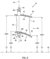
- the inner radial surface 44 of the shroud structure 36 at the axial inlet to the VGV assembly 32 is disposed a radial distance "SRD1" from the central axis 30.
- the inner radial surface 44 of the shroud structure 36 at the axial exit to the VGV assembly 32 is disposed a radial distance "SRD2" from the central axis 30.
- the inner radial surface 44 of the shroud structure 36 is contoured such that the radial distance at the VGV inlet (SRD1) is different from the radial distance at the VGV exit (SRD2); e.g., the inner radial surface 44 of the shroud structure 36 between the VGV inlet and the VGV exit may be arcuately shaped for aerodynamic purposes.
- the outer radial surface 46 of the hub structure 38 extends an axial distance radially inside the VGV assembly 32.
- the outer radial surface 46 of the hub structure 38 at the axial inlet to the VGV assembly 32 is disposed a radial distance "HRD1" from the central axis 30.
- the outer radial surface 46 of the hub structure 38 at the axial exit to the VGV assembly 32 is disposed a radial distance "HRD2" from the central axis 30.
- the outer radial surface 46 of the hub structure 38 is contoured such that the radial distance at the VGV inlet (HRD1) is different from the radial distance at the VGV exit (HRD2); e.g., the outer radial surface 46 of the hub structure 38 between the VGV inlet and the VGV exit may be arcuately shaped for aerodynamic purposes.
- FIG. 3 illustrates an arcuately shaped shroud structure inner radial surface 44 between the VGV inlet and the VGV exit, and an arcuately shaped hub structure outer radial surface 46 between the VGV inlet and the VGV exit.
- the geometric configuration of the shroud structure 36 between the VGV inlet and exit may mirror the geometric configuration of the hub structure 38 between the VGV inlet and exit, or the two surfaces may not mirror one another.
- FIG. 3 diagrammatically illustrates a hub structure 38 and a shroud structure 36 that do not mirror one another between the VGV inlet and exit.
- the present disclosure is not limited to any particular hub structure 38 geometric configuration between the VGV inlet and exit or any particular shroud structure 36 geometric configuration between the VGV inlet and exit.
- the amount of vane 34 angular rotation often depends on the VGV assembly 32 application.
- a typical vane 34 angular rotation is twenty to seventy-five degrees (20-75°).
- the present disclosure is not limited to any particular vane 34 angular rotation range.
- the particular angle that the vanes 34 within the VGV assembly 32 are disposed relative to airflow direction during the operation of the engine 20 may be defined by the then operational constraints; e.g., the vane angle theta preferred for a maximum power setting may be different than the vane angle theta preferred for a cruise power setting, etc.
- An advantage of a VGV assembly 32, as opposed to a vane 34 disposed at a fixed angle, is that the vane angle can be tailored to the operational needs.
- Rotation of the vanes 34 between first and second rotational positions must consider the differences in the shroud structure inner radial surface 44 radius between the VGV inlet and the VGV exit (i.e., between SRD1 and SRD2 - see FIG. 3 ), and the differences in the hub structure outer radial surface 46 radius between the VGV inlet and the VGV exit (i.e., between HRD1 and HRD2 - see FIG. 3 ). Failure to consider these inner and outer gas path surfaces may result in contact between the vane inner radial end 39 and the hub 38, or contact between the vane outer radial end 41 and the shroud 36, or both.
- VGV assemblies accommodate the aforesaid shroud and hub geometries by increasing the clearance between the vane inner radial end 39 and the hub 38, or between the vane outer radial end 41 and the shroud 36, or both. As stated in the Background of the Invention, however, increasing the aforesaid clearances can result in undesirable leakage that may lower engine efficiency and create undesirable airflow anomalies.
- the present disclosure provides an improvement that considers the contour of the shroud structure inner radial surface 44, and the contour of the hub outer radial surface 46 radius between the VGV inlet and the VGV exit by "linearly” translating the vane 34 as the vane 34 is rotated.
- linear translation refers to axial translation between the vane inner or outer radial post 43, 45 and a mechanism for rotational and linear translation of the vane 34 ("RT mechanism 40") which equates to radial translation of the vane 34 within the VGV assembly 32 relative to the central axis 30.
- the clearance gap between the vane inner radial end 39 and the hub 38 and the clearance gap between the vane outer radial end 41 and the shroud 36 can be maintained to decrease the aforesaid undesirable leakage.
- the present disclosure RT mechanism 40 facilitates rotational movement of the vane 34, permits customized linear translation, and is cost effective to manufacture.
- the present disclosure includes an RT mechanism 40 that includes a vane 34 with an outer radial post 45 having at least one pin 48 that extends perpendicularly outwardly from the outer radial post 45 (i.e., perpendicular to the rotational axis 47 of the vane 34), and a collar 50 having an inner bore 52 configured to receive the outer radial post 45.
- the collar 50 includes an outer radial surface 54 and an inner bore surface 56, the latter defining the inner bore 52.
- the outer radial surface 54 and the inner bore surface 56 extend axially between a first axial end 57 and a second axial end 59.
- At least one ramp slot 58 may extend from the inner bore surface 56 through to the outer radial surface 54 of the collar 50.
- the ramp slot 58 is configured to receive the pin 48 and has a length that extends a distance between a ramp slot first lengthwise end 60 and a second lengthwise end 62.
- the length of the ramp slot 58 extends circumferentially and is disposed at a skewed angle that produces an axial rise; i.e., the first lengthwise end 60 of the ramp slot 58 is disposed at a collar axial position different from that of the second lengthwise end 62.
- the axial distance between the first lengthwise end 60 of the ramp slot 58 and the second lengthwise end 62 is labeled in FIG. 5 as the axial rise.
- the ramp slot 58 may be described as extending between the first and second lengthwise ends 60, 62 in a direction of travel that includes a circumferential component and an axial component.
- the circumferential component relates to the amount of vane 34 travel possible and the axial component relates to the amount of relative axial travel between the outer radial post 45 and the collar 50 that is possible during the aforesaid rotation.
- the outer radial post 45 is slidably received within the collar inner bore 52.
- the pin 48 extends through the ramp slot 58 and constrains relative movement between the collar 50 and the outer radial post 45.
- the pin 48 extending into or through the ramp slot 58 causes relative axial translation between the collar 50 and the outer radial post 45 (and therefore radial translation of the vane 34 relative to the central axis 30) during vane 34 rotation.
- the collar 50 may be positionally fixed so that rotation of the vane 34 causes the vane 34 to axially translate within the collar inner bore 52 as the vane 34 is rotated (which equates to radial translation of the vane 34 relative to the central axis 30).
- the pin 48 / ramp slot 58 may be disposed vice versa; i.e., the ramp slot may be disposed in the outer radial post 45 and the pin disposed in the collar 50.
- this RT mechanism 40 embodiment may have more than one pin 48 and ramp slot 58 pair; e.g. two pairs disposed 180 degrees from one another.
- the axial rise of the ramp slot 58 (i.e., the difference in collar 50 axial position between the first and second lengthwise ends of the ramp slot 58) is chosen to cause the rotating vane 34 to track with the hub outer radial surface 46 and the shroud inner radial surface 44 and thereby avoid clearance gaps that would otherwise potentially cause undesirable leakage.
- the pin 48 / ramp slot 58 is understood to provide significant utility. For example, the amount of surface contact between the pin 48 and ramp slot 58 is substantially less that would be the case if two opposing ramp surfaces extending for most of the circumference were in contact. The decreased amount of contact surface is understood to decrease contact friction and therefore facilitate rotational movement.
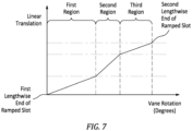
- the pin 48 / ramp slot 58 embodiment of the RT mechanism 40 facilitates embodiments wherein it is desirable to linearly translate the vane 34 (during rotation) in a manner other than a constant slope.
- a non-constant slope include an arcuate path that includes multiple radii, or a path that includes a plurality of slopes; i.e., greater slope for portions of the vane rotation and lesser slope for other portions of the vane rotation.
- the graph shown in FIG. 7 diagrammatically shows the vane 34 rotation between the first and second lengthwise ends of the ramp slot 58 in a first region, a second region, and a third region.
- first and third slopes are substantially equal but different than the second slope.
- the linear translation of the vane 34 may be customized to produce desirable clearance gaps for the entirety of the vane 34 rotation.
- the ability of the RT mechanism 40 to translate the vane 34 linearly in a defined manner that tracks with the hub 38 and shroud 36 may enable hub 38 and/or shroud 36 contours (aerodynamically enhanced) otherwise unfeasible.
- the ramp slot 58 configuration diagrammatically shown in FIG. 7 is provided for illustrative purposes and the present disclosure is not limited thereto.
- the above RT mechanism 40 embodiment is described in terms of a pin 48 extending outwardly from a vane outer radial post 45 (e.g., perpendicular to the rotational axis of the vane) and a collar 50 in communication with the vane outer radial post 45.
- the RT mechanism 40 may be disposed at the inner radial post 43; i.e., a pin 48 extending outwardly from a vane inner radial post 43 and a collar 50 in communication with the vane inner radial post 43.
- the present disclosure contemplates that the pin 48 may extend through the entire collar 50 wall or less than the entire collar 50 wall.
- some embodiments may include a first RT mechanism 40 as described above disposed at the outer radial post 45 and a second RT mechanism 40 as described above at the inner radial post 43 working in concert with one another.
- the collar 50 is described above as being static or non-rotational relative to the vane 34.
- the collar 50 may be independent of the shroud 36 or the hub 38, supported by the shroud 36 or hub 38 or by other structure, or the collar 50 may be integral with the shroud 36 or hub 38.
- another RT mechanism 40 embodiment includes at least one pin 148 that extends outwardly from the vane 34 (e.g., at the outer radial end 41) adjacent to and substantially parallel with the outer radial post 45 (i.e., substantially parallel to the rotational axis 47 of the vane), and a ramp spacer 64.
- the ramp spacer 64 includes an outer radial surface 66, an inner bore surface 68, a first axial end surface 70, and a second axial end surface 72.
- the inner bore surface 68 defines the inner bore 74 and the inner bore 74 is configured to slidably receive the outer radial post 45 (or inner radial post).
- the ramp spacer 64 is static or non-rotational relative to the vane 34.
- the ramp spacer 64 may be independent of the shroud 36 or the hub 38, supported by the shroud 36 or hub 38 or by other structure, or the ramp spacer 64 may be integral with the shroud 36 or hub 38.
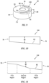
- the ramp spacer 64 includes at least one ramp slot 158 disposed in the first axial end surface 70 of the ramp spacer 64.
- the ramp slot 158 extends a circumferential distance around the inner bore 74, extending from a first lengthwise end 76 to a second lengthwise end 78.
- the ramp slot 158 includes a width configured to receive the pin 148, a slot depth 80, and a slot base surface 82 disposed at the slot depth 80.
- the slot depth 80 disposed at the first lengthwise end is less than the slot depth 80 at the second lengthwise end.
- the ramp slot 158 diagrammatically shown in FIG.
- FIG. 10 illustrates a slot depth 80 that linearly changes (i.e., constant slope) from the first lengthwise end 76 to the second lengthwise end 78.
- the present disclosure is not limited to a ramp slot 158 having a depth 80 that changes linearly.
- the pin 148 When assembled, the pin 148 is received within the ramp slot 158 in contact with the slot base surface 82. Rotation of the vane 34 (and attached pin 148) relative to the positionally fixed ramp spacer 64 causes translation of the vane 34 toward or away from the ramp spacer 64 (and therefore radial translation of the vane 34 relative to the central axis 30) as the pin 148 in contact with the slot base surface 82 translates along the varying depth ramp slot 158.
- This RT mechanism 40 embodiment may have more than one pin 148 and ramp slot 158 pair; e.g. two pairs disposed 180 degrees from one another.
- the varying depth 80 of the ramp slot 158 (i.e., the ramp slot depth 80 difference between the first and second lengthwise ends 76, 78 of the ramp slot 158) is chosen to cause the rotating vane 34 to track with the hub outer radial surface 46 and the shroud inner radial surface 44 and thereby avoid clearance gaps that would otherwise potentially cause undesirable leakage.
- the pin 148 / ramp slot 158 is understood to provide significant utility. For example, the amount of surface contact between the pin 148 and the slot base surface 82 is substantially less that would be the case if two opposing ramp surfaces extending for most of the circumference were in contact. The decreased amount of contact surface is understood to decrease contact friction and therefor facilitate rotational movement.
- the pin 148 / ramp slot 158 embodiment of the RT mechanism 40 facilitates embodiments wherein it is desirable to linearly translate the vane 34 (during rotation) in a manner other than a linear slope.
- a non-constant slope include an arcuate path that includes multiple radii, or a path that includes a plurality of slopes; i.e., greater slope for portions of the vane 34 rotation and lesser slope for other portions of the vane 34 rotation.
- the ramp slot 158 diagrammatically shown in FIG. 11 illustrates a slot depth 80 that having a first, second, and third ramp slot regions.
- first and third slopes are substantially equal but different than the second slope.
- the linear translation of the vane 34 may be customized to produce desirable clearance gaps for the entirety of the vane 34 rotation.
- the ability of the RT mechanism 40 to translate the vane 34 linearly in a defined manner that tracks with the hub 38 and shroud 36 may enable hub 38 and/or shroud 36 contours (aerodynamically enhanced) otherwise unfeasible.
- the ramp slot 158 configurations shown in FIGS. 10 and 11 are provided for illustrative purposes and the present disclosure is not limited thereto.
- the RT mechanism 40 embodiment like that shown in FIG. 8 may include a biasing member 84 that, when the VGV assembly 32 is assembled, applies a biasing force against the vane 34 to facilitate maintaining contact between the pin 148 and the slot base surface 82 and deters undesired vibrational or loose movement of vane 34 relative to the ramp spacer 64.
- the biasing member 84 may be configured such that compression of the biasing member 84 is resisted consequently producing the biasing force that biases the pin 148 into contact with the slot base surface 82.
- the biasing member 84 may be configured in a variety of different ways.
- the biasing member 84 may be a wave spring, a coil spring, a machined spring, a Belleville washer, an elastomeric member, or the like.
- the above RT mechanism 40 embodiment is described in terms of a pin 148 extending outwardly from the vane 34 (e.g., out from the inner radial end 39) adjacent the vane outer radial post 45 (e.g., substantially parallel to the rotational axis 47 of the vane 34) and a ramp spacer 64 in communication with the vane outer radial post 45 and the pin 148.
- the RT mechanism 40 may be disposed at the inner radial post 43; i.e., a pin 148 extending outwardly from the vane 34 adjacent the inner radial post 43 and a ramp spacer 64 in communication with the vane inner radial post 43 and the pin 148 extending outwardly from the vane 34.
- some embodiments may include a first RT mechanism 40 as described above disposed at the outer radial post 45 and a second RT mechanism 40 as described above at the inner radial post 43 working in concert with one another.
Landscapes
- Engineering & Computer Science (AREA)
- Mechanical Engineering (AREA)
- General Engineering & Computer Science (AREA)
- Structures Of Non-Positive Displacement Pumps (AREA)
- Turbine Rotor Nozzle Sealing (AREA)
Applications Claiming Priority (1)
| Application Number | Priority Date | Filing Date | Title |
|---|---|---|---|
| US17/879,488 US11965422B2 (en) | 2022-08-02 | 2022-08-02 | Variable guide vane assembly for gas turbine engine |
Publications (1)
| Publication Number | Publication Date |
|---|---|
| EP4317657A1 true EP4317657A1 (de) | 2024-02-07 |
Family
ID=87555153
Family Applications (1)
| Application Number | Title | Priority Date | Filing Date |
|---|---|---|---|
| EP23189310.8A Pending EP4317657A1 (de) | 2022-08-02 | 2023-08-02 | Variable leitschaufelanordnung für gasturbinenmotor |
Country Status (3)
| Country | Link |
|---|---|
| US (2) | US11965422B2 (de) |
| EP (1) | EP4317657A1 (de) |
| CA (1) | CA3208150A1 (de) |
Citations (9)
| Publication number | Priority date | Publication date | Assignee | Title |
|---|---|---|---|---|
| US4773817A (en) * | 1986-09-03 | 1988-09-27 | Societe Nationale D'etude Et De Construction De Moteurs D'aviation "S.N.E.C.M.A." | Labyrinth seal adjustment device for incorporation in a turbomachine |
| US5362202A (en) * | 1992-10-07 | 1994-11-08 | Societe Nationale D'etude Et De Construction De Moteurs D'aviation "Snecma" | Turbomachine equipped with means for adjusting the play between the stator blades and the rotor of a compressor |
| US20180371938A1 (en) * | 2017-06-23 | 2018-12-27 | Rolls-Royce North American Technologies Inc. | Method and Configuration for Improved Variable Vane Positioning |
| US20200141331A1 (en) * | 2018-11-06 | 2020-05-07 | Rolls-Royce Plc | Actuation system |
| US11092167B2 (en) | 2018-08-28 | 2021-08-17 | Pratt & Whitney Canada Corp. | Variable vane actuating system |
| US11092032B2 (en) | 2018-08-28 | 2021-08-17 | Pratt & Whitney Canada Corp. | Variable vane actuating system |
| US11346241B2 (en) | 2020-05-28 | 2022-05-31 | Pratt & Whitney Canada Corp. | Variable guide vanes assembly |
| US11359509B1 (en) | 2020-11-23 | 2022-06-14 | Pratt & Whitney Canada Corp. | Variable guide vane assembly with bushing ring and biasing member |
| US11372380B2 (en) | 2019-10-15 | 2022-06-28 | UiPath, Inc. | Media-to-workflow generation using artificial intelligence (AI) |
Family Cites Families (2)
| Publication number | Priority date | Publication date | Assignee | Title |
|---|---|---|---|---|
| US20140140822A1 (en) * | 2012-11-16 | 2014-05-22 | General Electric Company | Contoured Stator Shroud |
| US10495108B2 (en) | 2017-01-31 | 2019-12-03 | Honeywell International Inc. | Variable vane devices containing rotationally-driven translating vane structures and methods for the production thereof |
-
2022
- 2022-08-02 US US17/879,488 patent/US11965422B2/en active Active
-
2023
- 2023-08-01 CA CA3208150A patent/CA3208150A1/en active Pending
- 2023-08-02 EP EP23189310.8A patent/EP4317657A1/de active Pending
-
2024
- 2024-04-22 US US18/642,083 patent/US12312967B2/en active Active
Patent Citations (9)
| Publication number | Priority date | Publication date | Assignee | Title |
|---|---|---|---|---|
| US4773817A (en) * | 1986-09-03 | 1988-09-27 | Societe Nationale D'etude Et De Construction De Moteurs D'aviation "S.N.E.C.M.A." | Labyrinth seal adjustment device for incorporation in a turbomachine |
| US5362202A (en) * | 1992-10-07 | 1994-11-08 | Societe Nationale D'etude Et De Construction De Moteurs D'aviation "Snecma" | Turbomachine equipped with means for adjusting the play between the stator blades and the rotor of a compressor |
| US20180371938A1 (en) * | 2017-06-23 | 2018-12-27 | Rolls-Royce North American Technologies Inc. | Method and Configuration for Improved Variable Vane Positioning |
| US11092167B2 (en) | 2018-08-28 | 2021-08-17 | Pratt & Whitney Canada Corp. | Variable vane actuating system |
| US11092032B2 (en) | 2018-08-28 | 2021-08-17 | Pratt & Whitney Canada Corp. | Variable vane actuating system |
| US20200141331A1 (en) * | 2018-11-06 | 2020-05-07 | Rolls-Royce Plc | Actuation system |
| US11372380B2 (en) | 2019-10-15 | 2022-06-28 | UiPath, Inc. | Media-to-workflow generation using artificial intelligence (AI) |
| US11346241B2 (en) | 2020-05-28 | 2022-05-31 | Pratt & Whitney Canada Corp. | Variable guide vanes assembly |
| US11359509B1 (en) | 2020-11-23 | 2022-06-14 | Pratt & Whitney Canada Corp. | Variable guide vane assembly with bushing ring and biasing member |
Also Published As
| Publication number | Publication date |
|---|---|
| US20240271545A1 (en) | 2024-08-15 |
| US12312967B2 (en) | 2025-05-27 |
| US11965422B2 (en) | 2024-04-23 |
| US20240044259A1 (en) | 2024-02-08 |
| CA3208150A1 (en) | 2024-02-02 |
Similar Documents
| Publication | Publication Date | Title |
|---|---|---|
| CN109519224B (zh) | 包括涡轮转子组件的燃气涡轮发动机 | |
| US20220170381A1 (en) | Variable guide vane assembly and vane arms therefor | |
| CN106481459B (zh) | 可变桨距风扇桨距范围限制器 | |
| US11578611B2 (en) | Variable guide vane assembly and bushings therefor | |
| EP4001596B1 (de) | Gasturbinentriebwerk | |
| US10227930B2 (en) | Compressor bleed systems in turbomachines and methods of extracting compressor airflow | |
| EP4039943B1 (de) | Gasturbinentriebwerk | |
| EP4006315B1 (de) | Leitschaufel mit verstellbarer anstellung für ein gasturbinentriebwerk und verfahren zum betreiben von nebenstehenden in einem ringförmigen gasweg eines gasturbinentriebwerks angeordneten erster und zweiter leitschaufeln mit verstellbarer anstellung | |
| JP2017110642A (ja) | ガスタービンエンジンの間隙の制御のコンプライアントなシュラウド | |
| CN112443364B (zh) | 用于同心可变定子静叶的促动组件 | |
| WO2024096879A1 (en) | Gas turbine engine with third stream | |
| EP4317657A1 (de) | Variable leitschaufelanordnung für gasturbinenmotor | |
| CN116696485B (zh) | 具有改进的导向轮叶配置的燃气涡轮发动机 | |
| CN118499085A (zh) | 用于燃气涡轮发动机的密封构件支撑系统 | |
| US8851832B2 (en) | Engine and vane actuation system for turbine engine | |
| CN114060098B (zh) | 包括空气制动元件的涡轮叶片及其使用方法 | |
| US12025053B1 (en) | Cantilever stator vane with damper | |
| US12460557B1 (en) | Variable pitch airfoil assembly for a gas turbine engine | |
| US12480419B1 (en) | Outer air seal (OAS) assembly for a gas turbine engine | |
| US12146422B2 (en) | Gas turbine engine including a rotating blade assembly | |
| US12258923B2 (en) | Cowl assembly for a propulsor | |
| US20230235680A1 (en) | Non-uniform turbomachinery blade tips for frequency tuning | |
| EP4512999A1 (de) | Schwalbenschwanzstruktur für turbinenrotor mit keilen | |
| CN118407813A (zh) | 涡轮翼型件 |
Legal Events
| Date | Code | Title | Description |
|---|---|---|---|
| PUAI | Public reference made under article 153(3) epc to a published international application that has entered the european phase |
Free format text: ORIGINAL CODE: 0009012 |
|
| STAA | Information on the status of an ep patent application or granted ep patent |
Free format text: STATUS: THE APPLICATION HAS BEEN PUBLISHED |
|
| AK | Designated contracting states |
Kind code of ref document: A1 Designated state(s): AL AT BE BG CH CY CZ DE DK EE ES FI FR GB GR HR HU IE IS IT LI LT LU LV MC ME MK MT NL NO PL PT RO RS SE SI SK SM TR |
|
| STAA | Information on the status of an ep patent application or granted ep patent |
Free format text: STATUS: REQUEST FOR EXAMINATION WAS MADE |
|
| 17P | Request for examination filed |
Effective date: 20240807 |
|
| RBV | Designated contracting states (corrected) |
Designated state(s): AL AT BE BG CH CY CZ DE DK EE ES FI FR GB GR HR HU IE IS IT LI LT LU LV MC ME MK MT NL NO PL PT RO RS SE SI SK SM TR |
|
| STAA | Information on the status of an ep patent application or granted ep patent |
Free format text: STATUS: EXAMINATION IS IN PROGRESS |
|
| 17Q | First examination report despatched |
Effective date: 20250821 |