EP4317701A1 - Soufflante d'air électrique et ventilateur - Google Patents
Soufflante d'air électrique et ventilateur Download PDFInfo
- Publication number
- EP4317701A1 EP4317701A1 EP22779573.9A EP22779573A EP4317701A1 EP 4317701 A1 EP4317701 A1 EP 4317701A1 EP 22779573 A EP22779573 A EP 22779573A EP 4317701 A1 EP4317701 A1 EP 4317701A1
- Authority
- EP
- European Patent Office
- Prior art keywords
- fan
- cooling fan
- electric blower
- bracket
- rotating shaft
- Prior art date
- Legal status (The legal status is an assumption and is not a legal conclusion. Google has not performed a legal analysis and makes no representation as to the accuracy of the status listed.)
- Withdrawn
Links
Images






Classifications
-
- F—MECHANICAL ENGINEERING; LIGHTING; HEATING; WEAPONS; BLASTING
- F04—POSITIVE - DISPLACEMENT MACHINES FOR LIQUIDS; PUMPS FOR LIQUIDS OR ELASTIC FLUIDS
- F04D—NON-POSITIVE-DISPLACEMENT PUMPS
- F04D17/00—Radial-flow pumps, e.g. centrifugal pumps; Helico-centrifugal pumps
- F04D17/08—Centrifugal pumps
- F04D17/16—Centrifugal pumps for displacing without appreciable compression
- F04D17/165—Axial entry and discharge
-
- F—MECHANICAL ENGINEERING; LIGHTING; HEATING; WEAPONS; BLASTING
- F04—POSITIVE - DISPLACEMENT MACHINES FOR LIQUIDS; PUMPS FOR LIQUIDS OR ELASTIC FLUIDS
- F04D—NON-POSITIVE-DISPLACEMENT PUMPS
- F04D25/00—Pumping installations or systems
- F04D25/02—Units comprising pumps and their driving means
- F04D25/06—Units comprising pumps and their driving means the pump being electrically driven
- F04D25/0606—Units comprising pumps and their driving means the pump being electrically driven the electric motor being specially adapted for integration in the pump
-
- F—MECHANICAL ENGINEERING; LIGHTING; HEATING; WEAPONS; BLASTING
- F04—POSITIVE - DISPLACEMENT MACHINES FOR LIQUIDS; PUMPS FOR LIQUIDS OR ELASTIC FLUIDS
- F04D—NON-POSITIVE-DISPLACEMENT PUMPS
- F04D25/00—Pumping installations or systems
- F04D25/02—Units comprising pumps and their driving means
- F04D25/08—Units comprising pumps and their driving means the working fluid being air, e.g. for ventilation
- F04D25/082—Units comprising pumps and their driving means the working fluid being air, e.g. for ventilation the unit having provision for cooling the motor
-
- F—MECHANICAL ENGINEERING; LIGHTING; HEATING; WEAPONS; BLASTING
- F04—POSITIVE - DISPLACEMENT MACHINES FOR LIQUIDS; PUMPS FOR LIQUIDS OR ELASTIC FLUIDS
- F04D—NON-POSITIVE-DISPLACEMENT PUMPS
- F04D29/00—Details, component parts, or accessories
- F04D29/26—Rotors specially for elastic fluids
- F04D29/28—Rotors specially for elastic fluids for centrifugal or helico-centrifugal pumps for radial-flow or helico-centrifugal pumps
- F04D29/281—Rotors specially for elastic fluids for centrifugal or helico-centrifugal pumps for radial-flow or helico-centrifugal pumps for fans or blowers
-
- F—MECHANICAL ENGINEERING; LIGHTING; HEATING; WEAPONS; BLASTING
- F04—POSITIVE - DISPLACEMENT MACHINES FOR LIQUIDS; PUMPS FOR LIQUIDS OR ELASTIC FLUIDS
- F04D—NON-POSITIVE-DISPLACEMENT PUMPS
- F04D29/00—Details, component parts, or accessories
- F04D29/40—Casings; Connections of working fluid
- F04D29/42—Casings; Connections of working fluid for radial or helico-centrifugal pumps
- F04D29/4206—Casings; Connections of working fluid for radial or helico-centrifugal pumps especially adapted for elastic fluid pumps
- F04D29/4226—Fan casings
- F04D29/4253—Fan casings with axial entry and discharge
-
- F—MECHANICAL ENGINEERING; LIGHTING; HEATING; WEAPONS; BLASTING
- F04—POSITIVE - DISPLACEMENT MACHINES FOR LIQUIDS; PUMPS FOR LIQUIDS OR ELASTIC FLUIDS
- F04D—NON-POSITIVE-DISPLACEMENT PUMPS
- F04D29/00—Details, component parts, or accessories
- F04D29/40—Casings; Connections of working fluid
- F04D29/42—Casings; Connections of working fluid for radial or helico-centrifugal pumps
- F04D29/44—Fluid-guiding means, e.g. diffusers
- F04D29/441—Fluid-guiding means, e.g. diffusers especially adapted for elastic fluid pumps
- F04D29/444—Bladed diffusers
-
- F—MECHANICAL ENGINEERING; LIGHTING; HEATING; WEAPONS; BLASTING
- F04—POSITIVE - DISPLACEMENT MACHINES FOR LIQUIDS; PUMPS FOR LIQUIDS OR ELASTIC FLUIDS
- F04D—NON-POSITIVE-DISPLACEMENT PUMPS
- F04D29/00—Details, component parts, or accessories
- F04D29/58—Cooling; Heating; Diminishing heat transfer
- F04D29/5806—Cooling the drive system
Definitions
- the present disclosure relates to an electric blower and a cooling fan.
- the present disclosure relates to a cooling fan incorporated in a bypass-type blower motor.
- Electric blowers having motors are used in various electric apparatuses such as vacuum cleaners.
- the electric blowers each include a rotating fan such as a centrifugal fan that is attached to a rotating shaft of a motor to suck outside air.
- Known examples of the electric blowers include a bypass-type blower motor (e.g., see PTL 1).
- the bypass-type blower motor includes separately a cooling fan for cooling internal components of the motor from a centrifugal fan for compressing and sucking outside air.
- the cooling fan used in the bypass-type blower motor conventionally has a single-sided blade specification in which the cooling fan includes fan blades provided on only one side close to the motor.
- Common examples of this type of cooling fan include a radial fan of the single-sided blade specification.
- cooling fan blades of the cooling fan may be deformed by stress generated in the fan blades. This case may cause even a base plate holding the fan blades to be deformed to bring the cooling fan into contact with a bracket or the like, thereby causing a problem.
- the cooling fan of the single-sided blade specification has only one surface provided with the fan blades, so that the fan blades are required to be increased in height to increase the amount of cooling air.
- the fan blades of the cooling fan are increased in height, not only the fan blades are likely to be deformed, but also noise due to rotation of the cooling fan increases.
- the present disclosure has been made to solve the above problems. It is an object of the present disclosure to provide an electric blower and a cooling fan capable of suppressing deformation of the cooling fan and suppressing an increase in noise.
- an electric blower includes: a rotor including a rotating shaft and a rotor core; a motor case that houses the rotor; a rotating fan that is attached to the rotating shaft to suck outside air; a cooling fan that is attached to the rotating shaft to cool an internal space of the motor case; a first ventilation path through which an air flow generated by rotation of the rotating fan flows; and a second ventilation path through which an air flow generated by rotation of the cooling fan flows.
- the cooling fan is positioned between the rotating fan and the rotor core, and the cooling fan includes multiple first fan blades provided on a first side of the cooling fan, the first side facing the rotor core, and multiple second fan blades provided on a second side of the cooling fan, the second side being opposite to the rotor core.
- the cooling fan is preferably a resin molding.
- the first fan blades are preferably equal in height to the second fan blades.
- the electric blower preferably further includes a stator disposed surrounding the rotor core, and the stator preferably includes a wall positioned laterally to the cooling fan.
- the stator preferably includes a stator core and a winding coil wound around the stator core with an insulator interposed therebetween, and the wall is preferably a part of the insulator.
- the cooling fan is preferably equal in outer diameter dimension to the rotor core.
- the electric blower preferably further includes a fan case having an inlet port and covering the rotating fan, and a bracket positioned between the rotating fan and the cooling fan, and the first ventilation path and the second ventilation path are preferably separated by the bracket.
- An air guide for covering the bracket is preferably provided.
- the bracket has an outer periphery provided with a step.
- the fan case is preferably in contact with the step.
- the bracket may include a rib, and the rib may protrude toward the cooling fan.
- the electric blower preferably further includes a cover for covering the rib.
- a cooling fan according to an aspect of the present disclosure is the cooling fan attached to the rotating shaft of the electric blower being a bypass-type blower motor, and includes one surface provided with the multiple first fan blades and a surface provided with the multiple second fan blades, the surface being opposite to the one surface.
- the present disclosure enables suppressing deformation of the cooling fan and an increase in noise.
- the present description and the drawings each show an X-axis, a Y-axis, and a Z-axis that indicate three respective axes of a three-dimensional orthogonal coordinate system.
- the X-axis and the Y-axis are orthogonal to each other and are each orthogonal to the Z-axis.
- the present exemplary embodiments each show the Z-axis direction in which axis C of rotating shaft 13 extends.
- Fig. 1 is an external perspective view of electric blower 1 according to the first exemplary embodiment.
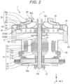
- Fig. 2 is a cross-sectional view of electric blower 1 according to the first exemplary embodiment in an XZ cross-section taken along a plane passing through axis C of rotating shaft 13.
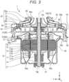
- Fig. 3 is a cross-sectional view of electric blower 1 according to the first exemplary embodiment in a YZ cross-section taken along a plane passing through axis C of rotating shaft 13.
- Figs. 2 and 3 mainly illustrate only line drawings appearing in a cross-section.
- Fig. 3 illustrates thick arrows that indicate flows of air.
- electric blower 1 includes motor 10, centrifugal fan 20 and cooling fan 70 that are each a rotating fan, air guide 30, fan case 40, motor case 50, and bracket 60.
- Motor 10 includes rotor 11 and stator 12.
- Centrifugal fan 20 and cooling fan 70 are attached to rotating shaft 13 of motor 10.
- Centrifugal fan 20 discharges air that flows into air guide 30.
- Centrifugal fan 20 and air guide 30 are covered with fan case 40.
- Motor case 50 houses motor 10.
- Motor case 50 is covered with bracket 60.
- Electric blower 1 is a bypass-type blower motor. That is, electric blower 1 separately includes cooling fan 70 for cooling internal components of motor 10 other than centrifugal fan 20 for sucking outside air as a main function of electric blower 1.
- Electric blower 1 being a bypass-type blower motor includes first ventilation path R1 through which an air flow generated by rotation of centrifugal fan 20 flows and second ventilation path R2 through which an air flow generated by rotation of cooling fan 70 flows, first ventilation path R1 and second ventilation path R2 being divided. First ventilation path R1 and second ventilation path R2 are spatially separated without intersecting each other. That is, the air flow does not flow back and forth between first ventilation path R1 and second ventilation path R2.
- Electric blower 1 can be used in an electric vacuum cleaner, for example.
- electric blower 1 being a bypass-type blower motor is used in a commercial rechargeable wet and dry vacuum cleaner.
- Motor 10 is an electric motor that rotates centrifugal fan 20.
- motor 10 is a DC motor that receives power from a DC power supply.
- Motor 10 is a commutator motor with a brush.
- motor 10 includes rotor 11, stator 12, rotating shaft 13, commutator 14, brush 15, first bearing 16, and second bearing 17.
- Rotor 11 (rotor) includes rotating shaft 13. Rotor 11 rotates about rotating shaft 13 using a magnetic force of stator 12. Rotor 11 is an inner rotor. As illustrated in Figs. 2 and 3 , rotor 11 is disposed inside stator 12. Specifically, rotor 11 is surrounded by stator 12 with a small air gap between rotor 11 and stator 12.
- Rotor 11 is an armature.
- Rotor 11 includes rotor core 11a (rotor iron core) and winding coil 11b (rotor coil) wound around rotor core 11a.
- Figs. 2 and 3 each schematically illustrate winding coil 1 1b.
- Rotor core 11a is a magnetic body made of a magnetic material.
- rotor core 11a is a stacked body in which multiple electromagnetic steel sheets are stacked in a direction (axial direction) in which axis C of rotating shaft 13 extends.
- Rotor core 11a includes multiple teeth protruding in a radial direction. When a current flows through winding coil 1 1b, each of the teeth generates a magnetic force that acts on stator 12.
- Stator 12 (stator) is disposed facing rotor 11. Stator 12 generates a magnetic force that acts on rotor 11. Stator 12 is disposed surrounding rotor 11. Specifically, stator 12 is disposed surrounding rotor core 11a of rotor 11. Stator 12 constitutes a magnetic circuit together with rotor 11 that is an armature. Stator 12 is fixed to motor case 50, for example.
- Stator 12 includes an air gap surface on which N poles and S poles alternately appear in a circumferential direction. As illustrated in Fig. 3 , stator 12 includes stator core 12a and winding coil 12b (stator coil). Stator core 12a includes multiple teeth that generate a main magnetic flux. Winding coil 12b (stator coil) is wound around stator core 12a with insulator 12c interposed therebetween.
- Stator core 12a is a stacked body in which multiple electromagnetic steel sheets are stacked in a direction of axis C of rotating shaft 13, for example.
- Stator core 12a faces rotor core 11a.
- stator core 12a surrounds rotor core 11a.
- Winding coil 12b is wound around each of the multiple teeth provided in stator core 12a.
- Insulator 12c is an insulating frame with which stator core 12a is covered.
- the teeth of stator core 12a are covered with insulator 12c.
- winding coil 12b is wound around insulator 12c covering the teeth. That is, insulator 12c is a winding frame around which winding coil 12b is wound.
- Insulator 12c is made of an insulating resin material such as polybutylene terephthalate (PBT), for example.
- PBT polybutylene terephthalate
- Stator 12 may be formed of a permanent magnet.
- stator 12 includes multiple permanent magnets disposed to cause N poles and S poles to alternately appear along the circumferential direction, for example.
- stator 12 includes wall 12d positioned laterally to cooling fan 70.
- Wall 12d is a part of insulator 12c. That is, wall 12d is formed integrally with insulator 12c.
- Wall 12d constitutes multiple walls 12d provided along the circumferential direction.
- wall 12d has an arc shape having a central angle of about 20° to 100° in top view, and walls 12d include paired walls 12d provided facing each other. Three or more walls 12d may be formed along the circumferential direction.
- Rotating shaft 13 serves as a center when rotor 11 rotates.
- Rotating shaft 13 extends in a longitudinal direction that is the direction of axis C of rotating shaft 13.
- Rotating shaft 13 is a metal rod, for example.
- Rotating shaft 13 is fixed to rotor 11.
- rotating shaft 13 is fixed to rotor core 11a while passing through the center of rotor core 11a of rotor 11, for example.
- rotating shaft 13 is fixed to rotor core 11a by press-fitting or shrink-fitting rotating shaft 13 into a center hole provided in rotor core 11a.
- Rotating shaft 13 includes one end part serving as first end part 13a (an end part close to centrifugal fan 20) that is supported by first bearing 16. First end part 13a of rotating shaft 13 protrudes from first bearing 16. Rotating shaft 13 protruding from first bearing 16 includes a leading end to which centrifugal fan 20 is attached. First bearing 16 is fixed to bracket 60.
- rotating shaft 13 includes the other end part serving as second end part 13b that is supported by second bearing 17.
- Second bearing 17 is fixed to a bottom of motor case 50. In this way, rotating shaft 13 is rotatably supported by first bearing 16 and second bearing 17.
- First bearing 16 and second bearing 17 are each a ball bearing, for example. However, first bearing 16 and second bearing 17 are each not limited to this.
- Rotating shaft 13 includes a first part (a part close to first bearing 16) to which centrifugal fan 20 is attached, the first part being referred to as an output shaft, and a second part (a part close to second bearing 17) on a side opposite to centrifugal fan 20, the second part being referred to as a counter output shaft.
- Commutator 14 is attached to rotating shaft 13. Thus, commutator 14 rotates together with rotating shaft 13. Commutator 14 is positioned closer to second bearing 17 than rotor core 11a in the direction of axis C of rotor core 11a. Specifically, commutator 14 is attached to a part of rotating shaft 13, the part being between rotor core 11a and second bearing 17.
- Commutator 14 includes multiple commutator segments arranged in an annular shape surrounding rotating shaft 13.
- the multiple commutator pieces are insulated and separated from each other in a rotation direction of rotating shaft 13.
- Each of the multiple commutator pieces is electrically connected to winding coil 1 1b of rotor 11.
- brush 15 is in contact with commutator 14.
- Brush 15 is a power supply brush for supplying electric power to rotor 11 by being in contact with commutator 14. Specifically, when brush 15 comes into contact with a commutator segment of commutator 14, an armature current is supplied to winding coil 1 1b of rotor 11 via commutator 14.
- brush 15 is a conductive carbon brush made of carbon.
- Brush 15 is an elongated substantially rectangular parallelepiped.
- Brush 15 is disposed to be able to be in sliding contact with commutator 14.
- Paired brushes 15 are provided in the present exemplary embodiment. Paired brushes 15 are disposed facing each other across commutator 14 so as to sandwich commutator 14. Specifically, each of paired brushes 15 includes an inner leading end in contact with commutator 14. Each of brushes 15 is in sliding contact with commutator 14 by receiving a pressing force from a brush spring such as a torsion spring, and is disposed to be movable in the radial direction from an outer periphery of rotating shaft 13 toward axis C thereof. Brushes 15 are housed in a brush holder, for example.
- Centrifugal fan 20 is an example of a rotating fan, and is rotated to suck air. Specifically, centrifugal fan 20 sucks air into an outer housing including fan case 40 and motor case 50. In the present exemplary embodiment, air is sucked into a space region between fan case 40 and bracket 60. Using centrifugal fan 20 as a rotating fan enables acquiring high suction pressure.
- Centrifugal fan 20 is attached to first end part 13a of rotating shaft 13 of motor 10, and is rotated by rotation of rotating shaft 13. Centrifugal fan 20 is fixed to a leading end part of rotating shaft 13 close to first end part 13a. Centrifugal fan 20 is fixed to rotating shaft 13 by press-fitting rotating shaft 13 into a through-hole provided in centrifugal fan 20, for example. A method for fixing centrifugal fan 20 to rotating shaft 13 is not limited to this. For example, centrifugal fan 20 may be inserted into rotating shaft 13 together with a fastening nut and a mounting plate to fasten the fastening nut, thereby being pressed and held by rotating shaft 13.
- Centrifugal fan 20 includes inlet port 20a (suction port) for sucking air and exhaust port 20b (blow-out port) for blowing out the air sucked from inlet port 20a.
- Inlet port 20a is a circular opening and is provided at the center of centrifugal fan 20.
- Multiple exhaust ports 20b are provided in a side part of centrifugal fan 20.
- Centrifugal fan 20 includes first side plate 21 (first fan plate) provided with inlet port 20a, second side plate 22 (second fan plate) facing first side plate 21 with a predetermined gap from first side plate 21, and multiple fan blades 23 disposed between first side plate 21 and second side plate 22.
- First side plate 21 is a shroud positioned on an upstream side.
- First side plate 21 is a tubular body in a flat and substantially truncated cone shape.
- Inlet port 20a is provided at the top of first side plate 21.
- Second side plate 22 is a hub positioned on a downstream side.
- Second side plate 22 is a flat plate in a flat and circular shape.
- Multiple fan blades 23 are sandwiched between first side plate 21 and second side plate 22.
- Multiple fan blades 23 are each a plate-shaped member curved in an arc shape and are disposed radially. Multiple fan blades 23 are disposed in a spiral shape at equal intervals.
- first side plate 21, and second side plate 22 surround a space that serves as a ventilation path through which air having flowed into centrifugal fan 20 from inlet port 20a passes.
- the ventilation path has a radially outer opening serving as exhaust port 20b.
- First side plate 21, second side plate 22, and multiple fan blades 23 are each formed of a metal plate made of aluminum, for example. Multiple fan blades 23 are fixed to first side plate 21 and second side plate 22 by caulking.
- Centrifugal fan 20 is disposed above bracket 60. Specifically, centrifugal fan 20 is disposed between fan case 40 and bracket 60.
- centrifugal fan 20 When centrifugal fan 20 is rotated, wind pressure is generated to suck air from inlet port 40a of fan case 40. Specifically, when centrifugal fan 20 is rotated, pressure near exhaust port 20b of centrifugal fan 20 increases to generate suction pressure, and thus external air is sucked from inlet port 40a of fan case 40. The air sucked into fan case 40 is sucked from inlet port 20a of centrifugal fan 20 and is blown out from exhaust port 20b, and then flows into air guide 30. That is, the air discharged from centrifugal fan 20 flows into air guide 30.
- Air guide 30 has a function of rectifying a flow of the air discharged from centrifugal fan 20 and exhausting the air to the outside of electric blower 1. Specifically, air guide 30 guides the air compressed by centrifugal fan 20 to the outside of electric blower 1 while gradually returning pressure of the air to atmospheric pressure. Air guide 30 is formed in a substantially annular ring shape as a whole. Air guide 30 is disposed surrounding centrifugal fan 20. Air guide 30 is disposed between fan case 40 and motor case 50. Specifically, air guide 30 is disposed between fan case 40 and bracket 60. Air guide 30 is made of a resin material, for example. Alternatively, air guide 30 may be made of a metal material.
- Air guide 30 includes multiple diffuser blades 31.
- Multiple diffuser blades 31 are each in the shape of a plate curved in an arc shape, and are each provided upright. Specifically, multiple diffuser blades 31 are disposed in a spiral manner as a whole. Air having flowed into air guide 30 is exhausted to the outside of electric blower 1 through multiple diffuser ventilation paths composed of multiple diffuser blades 31.
- the diffuser ventilation paths are each a part of first ventilation path R1.
- Fan case 40 is configured to cover centrifugal fan 20 and air guide 30. Fan case 40 is also configured to cover bracket 60. Fan case 40 includes lid 41 (first fan case) and side wall 42 (second fan case). Lid 41 is configured to cover an upper part of each of centrifugal fan 20 and air guide 30. Side wall 42 is configured to cover a side part of each of centrifugal fan 20 and air guide 30. Fan case 40 is a metal cover made of a metal material, for example. However, fan case 40 is not limited to this.
- Fan case 40 includes inlet port 40a (suction port) for sucking outside air.
- Inlet port 40a is a through-hole in a circular shape provided in the center of lid 41.
- Inlet port 40a of fan case 40 faces inlet port 20a of centrifugal fan 20. When centrifugal fan 20 is rotated, air flows into fan case 40 through inlet port 40a of fan case 40.
- Fan case 40 is fixed to bracket 60. Specifically, fan case 40 is fixed to bracket 60 by connecting side wall 42 of fan case 40 to an outer peripheral end of bracket 60 as illustrated in Fig. 2 .
- Fan case 40 is provided with fan case spacer 80 attached. Specifically, fan case spacer 80 is attached to fan case 40 while surrounding inlet port 40a of fan case 40. Providing fan case spacer 80 enables improvement in blowing efficiency of electric blower 1 as compared with when no fan case spacer 80 is provided.
- Motor case 50 is a housing (frame) that houses motor 10. Specifically, motor case 50 houses components constituting motor 10, such as rotor 11 and stator 12. Motor case 50 is an outer shell member (outer shell) of electric blower 1 and motor 10. Motor case 50 is a metal case made of a metal material, for example.
- Motor case 50 has a bottomed cylindrical shape with an opening.
- Motor case 50 includes a bottom and a side wall in a cylindrical shape.
- the opening of a cylindrical part of motor case 50 is covered with bracket 60 and fan case 40.
- the bottom and the side wall of motor case 50 are provided with multiple through-holes 50a.
- Multiple through-holes 50a each serve as an inlet port (suction port) for sucking air from the outside of motor case 50 when cooling fan 70 is rotated.
- the air sucked from each of through-holes 50a passes between stator core 12a and rotor core 11a, and between stator core 12a and motor case 50, and then flows in motor case 50 toward bracket 60.
- the air having flowed toward bracket 60 in motor case 50 is discharged to the outside through a gap formed between bracket 60 and motor case 50.
- gap 50b formed between bracket 60 and motor case 50 functions as an exhaust port (blow-out port).
- Motor case 50 also functions as a bracket that holds second bearing 17.
- motor case 50 includes bearing holder 51 that holds second bearing 17.
- Bearing holder 51 is provided at the bottom of motor case 50.
- Second bearing 17 is fixed to bearing holder 51 by adhesion, for example.
- Bracket 60 includes bearing holder 61 that holds first bearing 16. First bearing 16 is fixed to bearing holder 61 by adhesion, for example. Bracket 60 is disposed to cover the opening of the cylindrical part of motor case 50.
- Bracket 60 divides a space region surrounded by fan case 40 and motor case 50 into two upper and lower regions.
- Fan case 40 and bracket 60 surround a first space region on an upper side that serves as first ventilation path R1 through which an air flow generated by rotation of centrifugal fan 20 flows.
- Centrifugal fan 20 is disposed in the first space region.
- bracket 60 and motor case 50 surround a second space region on a lower side that serves as second ventilation path R2 through which an air flow generated by rotation of cooling fan 70 flows.
- Cooling fan 70 is disposed in the second space region.
- bracket 60 is disposed between centrifugal fan 20 and cooling fan 70.
- Bracket 60 separates first ventilation path R1 through which an air flow generated by centrifugal fan 20 flows from second ventilation path R2 through which an air flow generated by cooling fan 70 flows. That is, bracket 60 has a function of separating first ventilation path R1 from second ventilation path R2.
- bracket 60 is provided at the outer peripheral end with multiple exhaust ports 60a (blow-out ports) for blowing out air sucked by rotation of centrifugal fan 20. That is, exhaust port 60a is a through-hole for exhausting the air sucked into fan case 40 by centrifugal fan 20 to the outside of electric blower 1. As illustrated in Fig. 1 , multiple exhaust ports 60a are disposed at equal intervals along the circumferential direction in the outer peripheral end of bracket 60. Multiple exhaust ports 60a are provided for each diffuser ventilation path formed by two diffuser blades 31 adjacent to each other, for example. However, multiple exhaust ports 60a are not limited to this.
- Cooling fan 70 is an example of a rotating fan. Cooling fan 70 is attached to rotating shaft 13 of motor 10. Thus, cooling fan 70 is rotated by rotation of rotating shaft 13. Centrifugal fan 20 is also attached to rotating shaft 13, so that cooling fan 70 is rotated in conjunction with centrifugal fan 20 positioned above bracket 60.
- Cooling fan 70 is disposed below bracket 60 in the direction of axis C. Thus, cooling fan 70 faces centrifugal fan 20 across bracket 60. Cooling fan 70 is disposed between bracket 60 and rotor core 11a of rotor 11. That is, cooling fan 70 is positioned between centrifugal fan 20 and rotor core 1 1a of rotor 11 in the direction of axis C of rotating shaft 13.
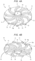
- Fig. 4A is a perspective view of cooling fan 70 mounted on electric blower 1 according to the first exemplary embodiment as viewed obliquely from above.
- Fig. 4B is a perspective view of cooling fan 70 mounted on electric blower 1 according to the first exemplary embodiment as viewed obliquely from below.
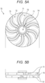
- Fig. 5A is a top view illustrating a configuration of cooling fan 70 mounted on electric blower 1 according to the first exemplary embodiment.
- Fig. 5B is a side view illustrating a configuration of cooling fan 70 mounted on electric blower 1 according to the first exemplary embodiment.
- cooling fan 70 includes multiple first fan blades 71, multiple second fan blades 72, and base 73.
- Base 73 has a disk shape.
- Base 73 includes first surface 73a and second surface 73b opposite to first surface 73a.
- First surface 73a of base 73 is an upper surface (close to bracket 60), and second surface 73b of base 73 is a lower surface.
- Base 73 is provided in its center with through-hole 74 into which rotating shaft 13 is inserted. Specifically, base 73 is provided in its center with a cylindrical part in which through-hole 74 is formed. Press-fitting rotating shaft 13 into through-hole 74 enables cooling fan 70 to be fixed at a predetermined position of rotating shaft 13.
- Cooling fan 70 has a double-sided blade specification. Cooling fan 70 includes multiple first fan blades 71 provided on one side in the direction of axis C of rotating shaft 13 and multiple second fan blades 72 provided on the other side therein.
- Multiple first fan blades 71 are provided on base 73 on a side opposite to rotor core 11a (i.e., a side close to centrifugal fan 20). Specifically, multiple first fan blades 71 are each provided protruding from first surface 73a of base 73 and extending on first surface 73a to form a ridge. Multiple first fan blades 71 are disposed at equal intervals in the circumferential direction and are disposed radially. Multiple first fan blades 71 each include a curved part. Multiple first fan blades 71 are disposed in a spiral manner. Multiple first fan blades 71 are all identical in shape. However, multiple first fan blades 71 are not limited to this.
- Multiple second fan blades 72 are provided on base 73 on a side close to rotor core 11a. Specifically, multiple second fan blades 72 are each provided protruding from second surface 73b of base 73 and extending on second surface 73b to form a ridge. Multiple second fan blades 72 are also disposed at equal intervals in the circumferential direction and are disposed radially. Multiple second fan blades 72 each include a curved part. Multiple second fan blades 72 are disposed in a spiral manner. Multiple second fan blades 72 are all identical in shape. However, multiple second fan blades 72 are not limited to this.
- first fan blade 71 and second fan blade 72 is formed extending radially outward from a central part of cooling fan 70 and being curved from the middle. First fan blade 71 and second fan blade 72 are curved in the same direction. First fan blade 71 and second fan blade 72 are curved in the same direction as fan blade 23 of centrifugal fan 20. Each of first fan blade 71 and second fan blade 72 extends with a constant width.
- first fan blades 71 and second fan blades 72 are alternately positioned one by one when cooling fan 70 is viewed from above. That is, first fan blade 71 is disposed at a position between two second fan blades 72 adjacent to each other. Similarly, second fan blade 72 is disposed at a position between two first fan blades 71 adjacent to each other.
- First fan blade 71 and second fan blade 72 are equal in width. First fan blade 71 and second fan blade 72 are equal in height. Specifically, first fan blade 71 and second fan blade 72 are identical in shape to each other.
- Cooling fan 70 configured as described above is a resin molding integrally molded with a resin material. That is, first fan blade 71, second fan blade 72, and base 73 are integrally made of resin. Available examples of the resin constituting cooling fan 70 include lightweight resins such as polybutylene terephthalate (PBT), polyethylene terephthalate (PET), and polypropylene (PP). The resin constituting cooling fan 70 may contain a reinforcing material such as a glass filler. As a result, cooling fan 70 can be improved in strength.
- PBT polybutylene terephthalate
- PET polyethylene terephthalate
- PP polypropylene
- the resin constituting cooling fan 70 may contain a reinforcing material such as a glass filler. As a result, cooling fan 70 can be improved in strength.
- cooling fan 70 has a smaller outer diameter than centrifugal fan 20. Cooling fan 70 is equal in outer diameter dimension to rotor core 11a of rotor 11. Cooling fan 70 is positioned laterally to wall 12d of stator 12. Specifically, cooling fan 70 is surrounded by wall 12d of stator 12. Wall 12d constitutes paired walls 12d, so that cooling fan 70 is interposed between paired walls 12d. Wall 12d preferably has an upper end positioned above first surface 73a (upper surface) of base 73 of cooling fan 70, and more preferably has an upper end positioned above an upper end of first fan blade 71 of cooling fan 70.
- Electric blower 1 configured as described above allows centrifugal fan 20 and cooling fan 70 attached to rotating shaft 13 of rotor 11 to be rotated when motor 10 is driven to rotate rotor 11.
- first ventilation path R1 rotation of centrifugal fan 20 generates an air flow in first ventilation path R1.
- air is sucked into fan case 40 from inlet port 40a of fan case 40 as indicated by thick arrows in Fig. 3 .
- the air sucked from inlet port 40a of fan case 40 is exhausted to the outside of electric blower 1 from multiple exhaust ports 60a of bracket 60 through first ventilation path R1.
- an inlet of first ventilation path R1 serves as inlet port 40a of fan case 40.
- an outlet of first ventilation path R1 serves as exhaust port 60a of bracket 60.
- centrifugal fan 20 flows into centrifugal fan 20 from inlet port 20a of centrifugal fan 20.
- the air having flowed into centrifugal fan 20 is blown radially outward of centrifugal fan 20 and exhausted from exhaust port 20b.
- the air sucked into centrifugal fan 20 is compressed under high pressure by centrifugal fan 20.
- the air exhausted from centrifugal fan 20 flows into air guide 30 surrounding centrifugal fan 20.
- the air having flowed into air guide 30 is decelerated and reduced in pressure by passing through the diffuser ventilation paths that are each gradually increased in cross-sectional area, and the air flows back along a ventilation path between a side part of air guide 30 and side wall 42 of fan case 40.
- the air having flowed back is exhausted from exhaust port 60a of bracket 60 to the outside of electric blower 1.
- cooling fan 70 generates an air flow in second ventilation path R2.
- air is sucked into motor case 50 from through-hole 50a by rotation of cooling fan 70 as indicated by the thick arrows in Fig. 3 .
- the sucked air generates an air flow inside motor case 50 due to rotation of cooling fan 70.
- the air flow generated inside motor case 50 passes through second ventilation path R2 and moves inside motor case 50 toward bracket 60.
- the air having flowed in the motor case 50 toward bracket 60 is discharged to the outside of electric blower 1 through gap 50b formed between motor case 50 and bracket 60. That is, an inlet of second ventilation path R2 is through-hole 50a of motor case 50, and an outlet of second ventilation path R2 is gap 50b.
- cooling fan 70 generates a flow of air flowing from through-hole 50a to gap 50b, i.e., an air flow, inside motor case 50.
- the generated air flow passes through second ventilation path R2 while cooling internal components of motor 10, such as rotor 11 and stator 12.
- the air sucked from through-hole 50a of motor case 50 is discharged to the outside of electric blower 1 together with heat taken out from the internal components of motor 10.
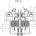
- FIG. 6 is a cross-sectional view of electric blower 1X according to Comparative Example 1.
- Fig. 7A is a perspective view of cooling fan 70X mounted on electric blower 1X according to Comparative Example 1
- Fig. 7B is a side view of cooling fan 70X.
- electric blower 1X of Comparative Example 1 is a bypass-type blower motor, and is different from electric blower 1 according to the above exemplary embodiment only in configuration of cooling fan 70X.
- cooling fan 70X (cooling fan of Comparative Example 1) mounted on electric blower 1X of Comparative Example 1 has a single-sided blade specification in which fan blades 71X are provided only on one surface close to motor 10, as illustrated in Figs. 7A and 7B .
- Electric blower 1X of Comparative Example 1 may cause fan blades 71X of cooling fan 70X to be deformed due to stress generated in fan blades 71X when cooling fan 70X is rotated at high speed together with centrifugal fan 20.
- base 73X holding fan blades 71X may be deformed to bring fan blades 71X into contact with internal components of electric blower 1X.
- base 73X may be deformed to bring a part of deformed base 73X into contact with bracket 60.
- cooling fan 70X is made of a metal material to have high strength.
- cooling fan 70X made of a metal material may cause increase in weight of cooling fan 70X, weight imbalance thereof, decrease in efficiency thereof, or vibration thereof.
- Cooling fan 70X of Comparative Example 1 includes only one surface provided with fan blades 71X. This configuration requires increase in height of fan blades 71X to increase cooling air amount. Unfortunately, when fan blades 71X of cooling fan 70X are increased in height, not only fan blades 71X are likely to be deformed, but also noise due to rotation of cooling fan 70X increases.
- cooling fan 70 mounted on electric blower 1 has a double-sided blade specification.
- cooling fan 70 includes multiple first fan blades 71 provided on one side in the direction of axis C of rotating shaft 13 and multiple second fan blades 72 provided on the other side therein.
- This configuration allows stresses generated in first fan blade 71 and second fan blade 72 to be cancelled each other when cooling fan 70 is rotated at high speed.
- this configuration enables reduction in deformation of cooling fan 70 as compared with cooling fan 70X of the single-sided blade specification. As a result, a part of deformed cooling fan 70 can be prevented from coming into contact with bracket 60 or the like.
- cooling fan 70 is composed of a resin molding made of a resin material as in the present exemplary embodiment instead of forming cooling fan 70 with a metal material, deformation of cooling fan 70 can be reduced. Additionally, even when cooling fan 70 is composed of a resin molding containing no glass filler or the like, deformation of cooling fan 70 can be reduced. That is, even cooling fan 70 composed of a resin molding has high strength.
- cooling fan 70 composed of a resin molding enables not only reduction in weight of cooling fan 70 but also reduction in imbalance of weight thereof as compared with cooling fan 70 made of a metal material. As a result, electric blower 1 can be reduced in weight, and vibration of electric blower 1 can be reduced.
- cooling air volume can be secured without increasing heights of first fan blades 71 and second fan blades 72 too much.
- electric blower 1 using cooling fan 70 includes first fan blade 71 and second fan blade 72 that are each low in height.
- noise caused by cooling fan 70 can be reduced while efficiency is maintained as compared with electric blower 1X using cooling fan 70X of Comparative Example 1.
- electric blower 1 includes rotor 11, motor case 50, centrifugal fan 20 that is a rotating fan, and cooling fan 70.
- Rotor 11 includes rotating shaft 13 and rotor core 11a.
- Motor case 50 houses rotor 11.
- Centrifugal fan 20 being a rotating fan is attached to rotating shaft 13 and sucks outside air.
- Cooling fan 70 is attached to rotating shaft 13 and cools an internal space of motor case 50.
- Electric blower 1 includes first ventilation path R1 and second ventilation path R2.
- First ventilation path R1 allows an air flow generated by rotation of centrifugal fan 20 to flow therethrough.
- Second ventilation path R2 allows an air flow generated by rotation of cooling fan 70 to flow therethrough.
- Cooling fan 70 is positioned between centrifugal fan 20 and rotor core 11a. Cooling fan 70 includes multiple first fan blades 71 and multiple second fan blades 72. Multiple first fan blades 71 are provided close to rotor core 11a. Multiple second fan blades 72 are provided opposite to rotor core 11a.
- This configuration enables reduction in deformation of cooling fan 70 even when cooling fan 70 is reduced in weight. At the same time, increase in noise can be suppressed while efficiency of electric blower 1 is maintained. Thus, electric blower 1 capable of satisfying demand for weight reduction, high efficiency, and low noise of a commutator motor can be fabricated.
- Electric blower 1 includes first fan blade 71 and second fan blade 72 that are equal in height.
- This configuration enables balancing stress generated in first fan blade 71 and stress generated in second fan blade 72. This configuration thus enables the stresses generated in first fan blade 71 and second fan blade 72 to be further offset. Thus, deformation of cooling fan 70 during high-speed rotation can be further reduced.
- First fan blade 71 and second fan blade 72 may be different in height.
- first fan blade 71 close to bracket 60 may be higher in height than second fan blade 72.
- cooling fan 70 deformed can be prevented from coming into contact with bracket 60 or the like as compared with when second fan blade 72 is higher in height than first fan blade 71.
- Electric blower 1 includes stator 12 provided with wall 12d positioned laterally to cooling fan 70. That is, wall 12d is positioned laterally to cooling fan 70.
- This configuration causes wall 12d to functions as a flow-regulating plate, and thus enabling increase in air volume (cooling air volume) of an air flow generated by rotation of cooling fan 70 as compared with when no wall 12d is provided.
- wall 12d of stator 12 is a part of insulator 12c of stator 12.
- This configuration enables increasing cooling air volume supplied by cooling fan 70 without separately providing a flow-regulating plate.
- Electric blower 1 includes cooling fan 70 that is equal in outer diameter dimension to rotor core 11a of rotor 11.
- This configuration enables increase in outer diameter dimension of cooling fan 70 as much as possible.
- the cooling air volume supplied by cooling fan 70 can be increased as much as possible.
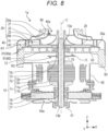
- FIG. 8 is a cross-sectional view of electric blower 1a according to the second exemplary embodiment in an XZ cross-section taken along a plane passing through axis C of rotating shaft 13.
- Electric blower 1a is different from electric blower 1 in that bracket 60 is covered with air guide 30a.
- Fig. 9 is a perspective view illustrating air guide 30a of electric blower 1a according to the second exemplary embodiment.
- Fig. 10 is a perspective view illustrating bracket 60 of electric blower 1a according to the second exemplary embodiment.
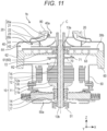
- FIG. 11 is a cross-sectional view of electric blower 1b according to the third exemplary embodiment in an XZ cross-section taken along a plane passing through axis C of rotating shaft 13.
- Electric blower 1b is different from electric blower 1 in that bracket 60 is covered with air guide 30b and no diffuser blade 31 according to the first exemplary embodiment is provided.
- Fig.12 is a perspective view illustrating air guide 30b of electric blower 1a according to the third exemplary embodiment.
- bracket 60 includes step 62 in its outer periphery as illustrated in Fig. 11 .
- Fan case 40 is in contact with step 62.
- Step 62 provided in the outer periphery of bracket 60 supports fan case 40.
- Step 62 determines a position at which fan case 40 is attached. That is, fan case 40 supported by step 62 provided in the outer periphery of bracket 60 has an outer periphery shared by the fan case and the bracket.
- a plurality of functions can be applied to the outer periphery of fan case 40 with minimum change in components.
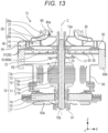
- FIG. 13 is a cross-sectional view of electric blower 1c according to the fourth exemplary embodiment in an XZ cross-section taken along a plane passing through axis C of rotating shaft 13.
- Electric blower 1c is different from electric blower 1 in that ribs 63 provided in bracket 60b protrude toward cooling fan 70.
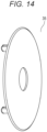
- Cover 35 is provided covering ribs 63.
- Fig. 14 is a perspective view illustrating cover 35 of electric blower 1c according to the fourth exemplary embodiment.
- bracket 60b When ribs 63 provided in bracket 60b protrudes toward cooling fan 70, air rotated by cooling fan 70 and air present between ribs 63 of bracket 60b interfere with each other, thereby generating a vortex. To solve this problem, cover 35 is provided.
- Ribs 63 provided in bracket 60b protrude toward cooling fan 70 and cover 35 is provided covering ribs 63 as described above, so that deterioration in performance of centrifugal fan 20 can be suppressed.
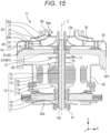
- FIG. 15 is a cross-sectional view of electric blower 1Y according to Comparative Example 2 in an XZ cross-section taken along a plane passing through axis C of rotating shaft 13.
- Electric blower 1Y is different from electric blower 1 in that bracket 60Y includes an upper surface and a lower surface that are each a flat surface.
- bracket 60Y can serve as air guide 30a and bracket 60 of the second exemplary embodiment, air guide 30b and bracket 60 of the third exemplary embodiment, and bracket 60b and cover 35 of the fourth exemplary embodiment.
- Comparative Example 2 allows bracket 60Y to serve as the air guide and the bracket.
- bracket 60Y requires a desired thickness.
- simply increasing thickness of bracket 60Y results in increase in weight of the bracket itself and increase in cost.
- the bracket needs to be reduced in weight while maintaining strength.
- the inventors have adopted a configuration in which a rib is formed on the bracket. This configuration enables suppressing deterioration in performance of centrifugal fan 20.
- FIG. 16 is a cross-sectional view of electric blower 1Z according to Comparative Example 3 in an XZ cross-section taken along a plane passing through axis C of rotating shaft 13.
- Bracket 60Z is formed by removing the ribs from bracket 60.
- bracket 60Z can serve as air guide 30a and bracket 60 of the second exemplary embodiment, air guide 30b and bracket 60 of the third exemplary embodiment, and bracket 60b and cover 35 of the fourth exemplary embodiment.
- bracket 60Z insufficient in strength may be conceivable.
- Cooling fan 70 includes first fan blade 71 and second fan blade 72 that are each formed extending radially outward from a central part of cooling fan 70 and being curved from the middle.
- first fan blade 71 and second fan blade 72 are each not limited to this.
- Fig. 17 is a top view of a cooling fan according to a modification. Specifically, first fan blades 71A and second fan blades 72A may be radially formed extending linearly outward in the radial direction from a central part of cooling fan 70A as in cooling fan 70A illustrated in Fig. 17 .
- motor 10 used in electric blower 1.
- motor 10 is not limited to this.
- electric blower 1 used in an electric vacuum cleaner is described.
- electric blower 1 is not limited to this.
- electric blower 1 may be used for another electric apparatus such as an air towel.
- the present disclosure also includes an aspect obtained by applying various modifications conceived by those skilled in the art to the exemplary embodiments above, or an aspect achieved by appropriately combining components and functions in the exemplary embodiments within a range without departing from the gist of the present disclosure.
- the technique of the present disclosure can be used for various electric apparatuses each using an electric blower.
Landscapes
- Engineering & Computer Science (AREA)
- Mechanical Engineering (AREA)
- General Engineering & Computer Science (AREA)
- Physics & Mathematics (AREA)
- Thermal Sciences (AREA)
- Structures Of Non-Positive Displacement Pumps (AREA)
- Motor Or Generator Cooling System (AREA)
Applications Claiming Priority (2)
| Application Number | Priority Date | Filing Date | Title |
|---|---|---|---|
| JP2021058501 | 2021-03-30 | ||
| PCT/JP2022/005382 WO2022209344A1 (fr) | 2021-03-30 | 2022-02-10 | Soufflante d'air électrique et ventilateur |
Publications (2)
| Publication Number | Publication Date |
|---|---|
| EP4317701A1 true EP4317701A1 (fr) | 2024-02-07 |
| EP4317701A4 EP4317701A4 (fr) | 2024-09-25 |
Family
ID=83455835
Family Applications (1)
| Application Number | Title | Priority Date | Filing Date |
|---|---|---|---|
| EP22779573.9A Withdrawn EP4317701A4 (fr) | 2021-03-30 | 2022-02-10 | Soufflante d'air électrique et ventilateur |
Country Status (4)
| Country | Link |
|---|---|
| EP (1) | EP4317701A4 (fr) |
| JP (1) | JPWO2022209344A1 (fr) |
| CN (1) | CN116997722A (fr) |
| WO (1) | WO2022209344A1 (fr) |
Family Cites Families (10)
| Publication number | Priority date | Publication date | Assignee | Title |
|---|---|---|---|---|
| DE2460294C3 (de) * | 1974-12-19 | 1981-07-30 | Bosch-Siemens Hausgeräte GmbH, 7000 Stuttgart | Garbehälter zum Backen, Braten und Grillen mit einem Heißluft-Umwälzgebläse, insbesondere Back- und Bratrohr mit pyrolytischer Selbstreinigung |
| JP2705343B2 (ja) * | 1991-04-09 | 1998-01-28 | 三菱電機株式会社 | 電動送風機 |
| JPH10164799A (ja) * | 1996-11-26 | 1998-06-19 | Hitachi Ltd | 誘導電動機 |
| DE10152733A1 (de) * | 2001-10-25 | 2003-05-08 | Bsh Bosch Siemens Hausgeraete | Gargerät mit einer Gebläseeinheit |
| GB0202835D0 (en) | 2002-02-07 | 2002-03-27 | Johnson Electric Sa | Blower motor |
| JP4599376B2 (ja) * | 2007-07-18 | 2010-12-15 | 三菱電機株式会社 | 回転電機 |
| JP6355390B2 (ja) * | 2014-04-02 | 2018-07-11 | 三菱電機株式会社 | 回転電機 |
| JP2018074893A (ja) * | 2016-11-02 | 2018-05-10 | 日本電産株式会社 | ロータ組立体 |
| JP7031684B2 (ja) * | 2017-11-30 | 2022-03-08 | 工機ホールディングス株式会社 | 電動工具 |
| JP7038074B2 (ja) * | 2019-03-22 | 2022-03-17 | 東芝三菱電機産業システム株式会社 | 回転電機およびロータシャフト |
-
2022
- 2022-02-10 EP EP22779573.9A patent/EP4317701A4/fr not_active Withdrawn
- 2022-02-10 WO PCT/JP2022/005382 patent/WO2022209344A1/fr not_active Ceased
- 2022-02-10 JP JP2023510603A patent/JPWO2022209344A1/ja active Pending
- 2022-02-10 CN CN202280022145.4A patent/CN116997722A/zh active Pending
Also Published As
| Publication number | Publication date |
|---|---|
| CN116997722A (zh) | 2023-11-03 |
| WO2022209344A1 (fr) | 2022-10-06 |
| EP4317701A4 (fr) | 2024-09-25 |
| JPWO2022209344A1 (fr) | 2022-10-06 |
Similar Documents
| Publication | Publication Date | Title |
|---|---|---|
| JP6599791B2 (ja) | 電動送風機および電気掃除機 | |
| CN108730209B (zh) | 电动鼓风机及搭载了该电动鼓风机的电动吸尘器 | |
| CN107614891A (zh) | 送风装置以及吸尘器 | |
| EP3760877A1 (fr) | Soufflante électrique, aspirateur électrique et sèche-mains | |
| US20190103783A1 (en) | Motor, blowing device, and cleaner | |
| CN213953999U (zh) | 送风装置及吸尘器 | |
| US11894721B2 (en) | Stator, electric motor, vacuum cleaner, and hand drying device | |
| EP3511575A1 (fr) | Soufflerie d'air et appareil de nettoyage | |
| WO2020255807A1 (fr) | Moteur électrique et souffleuse électrique | |
| KR102201386B1 (ko) | 팬 모터 | |
| WO2021100292A1 (fr) | Moteur électrique sans encoche, soufflante électrique et aspirateur électrique | |
| US20180209442A1 (en) | Blower device and cleaner | |
| JP6903036B2 (ja) | 電動送風機及びそれを搭載した電気掃除機 | |
| WO2020174878A1 (fr) | Moteur électrique et soufflante électrique | |
| CN114135501A (zh) | 旋转设备 | |
| JP6859074B2 (ja) | 電動機および電気掃除機 | |
| WO2022209344A1 (fr) | Soufflante d'air électrique et ventilateur | |
| JPWO2022209344A5 (fr) | ||
| JP2020054067A (ja) | 電動送風機およびそれを用いた電気掃除機 | |
| US20220120287A1 (en) | Electric blower | |
| US12158153B2 (en) | Blower | |
| CN114135502A (zh) | 旋转设备 | |
| US20250043791A1 (en) | Blower and vacuum cleaner | |
| EP4317703A1 (fr) | Soufflante électrique | |
| EP4130486A1 (fr) | Soufflante électrique |
Legal Events
| Date | Code | Title | Description |
|---|---|---|---|
| STAA | Information on the status of an ep patent application or granted ep patent |
Free format text: STATUS: THE INTERNATIONAL PUBLICATION HAS BEEN MADE |
|
| PUAI | Public reference made under article 153(3) epc to a published international application that has entered the european phase |
Free format text: ORIGINAL CODE: 0009012 |
|
| STAA | Information on the status of an ep patent application or granted ep patent |
Free format text: STATUS: REQUEST FOR EXAMINATION WAS MADE |
|
| 17P | Request for examination filed |
Effective date: 20231018 |
|
| AK | Designated contracting states |
Kind code of ref document: A1 Designated state(s): AL AT BE BG CH CY CZ DE DK EE ES FI FR GB GR HR HU IE IS IT LI LT LU LV MC MK MT NL NO PL PT RO RS SE SI SK SM TR |
|
| DAV | Request for validation of the european patent (deleted) | ||
| DAX | Request for extension of the european patent (deleted) | ||
| REG | Reference to a national code |
Ref country code: DE Ref legal event code: R079 Free format text: PREVIOUS MAIN CLASS: F04D0025160000 Ipc: F04D0025080000 |
|
| A4 | Supplementary search report drawn up and despatched |
Effective date: 20240827 |
|
| RIC1 | Information provided on ipc code assigned before grant |
Ipc: F04D 29/44 20060101ALI20240821BHEP Ipc: F04D 29/42 20060101ALI20240821BHEP Ipc: F04D 25/06 20060101ALI20240821BHEP Ipc: F04D 17/16 20060101ALI20240821BHEP Ipc: F04D 29/58 20060101ALI20240821BHEP Ipc: F04D 29/28 20060101ALI20240821BHEP Ipc: F04D 25/08 20060101AFI20240821BHEP |
|
| STAA | Information on the status of an ep patent application or granted ep patent |
Free format text: STATUS: THE APPLICATION IS DEEMED TO BE WITHDRAWN |
|
| 18D | Application deemed to be withdrawn |
Effective date: 20250314 |