EP4317711A2 - Machine de travail - Google Patents
Machine de travail Download PDFInfo
- Publication number
- EP4317711A2 EP4317711A2 EP23208373.3A EP23208373A EP4317711A2 EP 4317711 A2 EP4317711 A2 EP 4317711A2 EP 23208373 A EP23208373 A EP 23208373A EP 4317711 A2 EP4317711 A2 EP 4317711A2
- Authority
- EP
- European Patent Office
- Prior art keywords
- hydraulic fluid
- working machine
- management system
- thermal management
- heat
- Prior art date
- Legal status (The legal status is an assumption and is not a legal conclusion. Google has not performed a legal analysis and makes no representation as to the accuracy of the status listed.)
- Pending
Links
Images

Classifications
-
- E—FIXED CONSTRUCTIONS
- E02—HYDRAULIC ENGINEERING; FOUNDATIONS; SOIL SHIFTING
- E02F—DREDGING; SOIL-SHIFTING
- E02F9/00—Component parts of dredgers or soil-shifting machines, not restricted to one of the kinds covered by groups E02F3/00 - E02F7/00
- E02F9/20—Drives; Control devices
- E02F9/22—Hydraulic or pneumatic drives
- E02F9/226—Safety arrangements, e.g. hydraulic driven fans, preventing cavitation, leakage, overheating
-
- B—PERFORMING OPERATIONS; TRANSPORTING
- B60—VEHICLES IN GENERAL
- B60H—ARRANGEMENTS OF HEATING, COOLING, VENTILATING OR OTHER AIR-TREATING DEVICES SPECIALLY ADAPTED FOR PASSENGER OR GOODS SPACES OF VEHICLES
- B60H1/00—Heating, cooling or ventilating devices
- B60H1/00357—Air-conditioning arrangements specially adapted for particular vehicles
- B60H1/00378—Air-conditioning arrangements specially adapted for particular vehicles for tractor or load vehicle cabins
-
- B—PERFORMING OPERATIONS; TRANSPORTING
- B60—VEHICLES IN GENERAL
- B60H—ARRANGEMENTS OF HEATING, COOLING, VENTILATING OR OTHER AIR-TREATING DEVICES SPECIALLY ADAPTED FOR PASSENGER OR GOODS SPACES OF VEHICLES
- B60H1/00—Heating, cooling or ventilating devices
- B60H1/00357—Air-conditioning arrangements specially adapted for particular vehicles
- B60H1/00385—Air-conditioning arrangements specially adapted for particular vehicles for vehicles having an electrical drive, e.g. hybrid or fuel cell
- B60H1/00392—Air-conditioning arrangements specially adapted for particular vehicles for vehicles having an electrical drive, e.g. hybrid or fuel cell for electric vehicles having only electric drive means
-
- B—PERFORMING OPERATIONS; TRANSPORTING
- B60—VEHICLES IN GENERAL
- B60H—ARRANGEMENTS OF HEATING, COOLING, VENTILATING OR OTHER AIR-TREATING DEVICES SPECIALLY ADAPTED FOR PASSENGER OR GOODS SPACES OF VEHICLES
- B60H1/00—Heating, cooling or ventilating devices
- B60H1/02—Heating, cooling or ventilating devices the heat being derived from the propulsion plant
- B60H1/03—Heating, cooling or ventilating devices the heat being derived from the propulsion plant and from a source other than the propulsion plant
-
- B—PERFORMING OPERATIONS; TRANSPORTING
- B60—VEHICLES IN GENERAL
- B60H—ARRANGEMENTS OF HEATING, COOLING, VENTILATING OR OTHER AIR-TREATING DEVICES SPECIALLY ADAPTED FOR PASSENGER OR GOODS SPACES OF VEHICLES
- B60H1/00—Heating, cooling or ventilating devices
- B60H1/22—Heating, cooling or ventilating devices the heat source being other than the propulsion plant
-
- E—FIXED CONSTRUCTIONS
- E02—HYDRAULIC ENGINEERING; FOUNDATIONS; SOIL SHIFTING
- E02F—DREDGING; SOIL-SHIFTING
- E02F9/00—Component parts of dredgers or soil-shifting machines, not restricted to one of the kinds covered by groups E02F3/00 - E02F7/00
- E02F9/20—Drives; Control devices
- E02F9/2058—Electric or electro-mechanical or mechanical control devices of vehicle sub-units
- E02F9/2062—Control of propulsion units
- E02F9/207—Control of propulsion units of the type electric propulsion units, e.g. electric motors or generators
-
- E—FIXED CONSTRUCTIONS
- E02—HYDRAULIC ENGINEERING; FOUNDATIONS; SOIL SHIFTING
- E02F—DREDGING; SOIL-SHIFTING
- E02F9/00—Component parts of dredgers or soil-shifting machines, not restricted to one of the kinds covered by groups E02F3/00 - E02F7/00
- E02F9/20—Drives; Control devices
- E02F9/2058—Electric or electro-mechanical or mechanical control devices of vehicle sub-units
- E02F9/2062—Control of propulsion units
- E02F9/2075—Control of propulsion units of the hybrid type
-
- F—MECHANICAL ENGINEERING; LIGHTING; HEATING; WEAPONS; BLASTING
- F15—FLUID-PRESSURE ACTUATORS; HYDRAULICS OR PNEUMATICS IN GENERAL
- F15B—SYSTEMS ACTING BY MEANS OF FLUIDS IN GENERAL; FLUID-PRESSURE ACTUATORS, e.g. SERVOMOTORS; DETAILS OF FLUID-PRESSURE SYSTEMS, NOT OTHERWISE PROVIDED FOR
- F15B21/00—Common features of fluid actuator systems; Fluid-pressure actuator systems or details thereof, not covered by any other group of this subclass
- F15B21/04—Special measures taken in connection with the properties of the fluid
- F15B21/042—Controlling the temperature of the fluid
- F15B21/0423—Cooling
-
- F—MECHANICAL ENGINEERING; LIGHTING; HEATING; WEAPONS; BLASTING
- F15—FLUID-PRESSURE ACTUATORS; HYDRAULICS OR PNEUMATICS IN GENERAL
- F15B—SYSTEMS ACTING BY MEANS OF FLUIDS IN GENERAL; FLUID-PRESSURE ACTUATORS, e.g. SERVOMOTORS; DETAILS OF FLUID-PRESSURE SYSTEMS, NOT OTHERWISE PROVIDED FOR
- F15B21/00—Common features of fluid actuator systems; Fluid-pressure actuator systems or details thereof, not covered by any other group of this subclass
- F15B21/04—Special measures taken in connection with the properties of the fluid
- F15B21/042—Controlling the temperature of the fluid
- F15B21/0427—Heating
-
- B—PERFORMING OPERATIONS; TRANSPORTING
- B60—VEHICLES IN GENERAL
- B60Y—INDEXING SCHEME RELATING TO ASPECTS CROSS-CUTTING VEHICLE TECHNOLOGY
- B60Y2200/00—Type of vehicle
- B60Y2200/40—Special vehicles
- B60Y2200/41—Construction vehicles, e.g. graders, excavators
-
- F—MECHANICAL ENGINEERING; LIGHTING; HEATING; WEAPONS; BLASTING
- F15—FLUID-PRESSURE ACTUATORS; HYDRAULICS OR PNEUMATICS IN GENERAL
- F15B—SYSTEMS ACTING BY MEANS OF FLUIDS IN GENERAL; FLUID-PRESSURE ACTUATORS, e.g. SERVOMOTORS; DETAILS OF FLUID-PRESSURE SYSTEMS, NOT OTHERWISE PROVIDED FOR
- F15B21/00—Common features of fluid actuator systems; Fluid-pressure actuator systems or details thereof, not covered by any other group of this subclass
- F15B21/04—Special measures taken in connection with the properties of the fluid
-
- Y—GENERAL TAGGING OF NEW TECHNOLOGICAL DEVELOPMENTS; GENERAL TAGGING OF CROSS-SECTIONAL TECHNOLOGIES SPANNING OVER SEVERAL SECTIONS OF THE IPC; TECHNICAL SUBJECTS COVERED BY FORMER USPC CROSS-REFERENCE ART COLLECTIONS [XRACs] AND DIGESTS
- Y02—TECHNOLOGIES OR APPLICATIONS FOR MITIGATION OR ADAPTATION AGAINST CLIMATE CHANGE
- Y02T—CLIMATE CHANGE MITIGATION TECHNOLOGIES RELATED TO TRANSPORTATION
- Y02T10/00—Road transport of goods or passengers
- Y02T10/60—Other road transportation technologies with climate change mitigation effect
- Y02T10/70—Energy storage systems for electromobility, e.g. batteries
Definitions
- the present disclosure relates to a working machine, and a control method for such a working machine.
- ICEs internal combustion engines
- One such power source is electrical energy stored in batteries or other storage media that is used to provide energy to electric motors to operate such working machines.
- the batteries may be used as the sole source of power to the machine, or may be used in conjunction with an ICE in a so called “hybrid" configuration whereby power may be supplied from the battery to the electric motors alone, energy may be supplied from diesel fuel to power an internal combustion engine alone, or some combination of the two power sources may be utilised.
- hybrid configurations typically a smaller ICE will be provided than on a traditional machine with the power shortfall being supplied from the batteries and electric motor.
- ICEs produce a significant amount of waste heat in operation that may be utilised for heating parts of the working machine as required, such as the operator cabin. Such a source of heat may be reduced in a hybrid working machine, or be entirely non-existent in a solely electrically powered working machine.
- certain parts of a working machine may desirably be heated or cooled to maintain operating efficiency and operator comfort.
- the supply of energy to effect such heating or cooling may be problematic in certain circumstances in a pure electric working machine or a hybrid working machine in view of the reduced availability or quality of energy and waste heat to provide such heating or cooling.
- the use of electrical energy from the machine's batteries to provide such heating or cooling may reduce the available energy for such a machine to perform working operations, between periods of charging where the machine may not be operable, thereby compromising the working efficiency of the machine.
- the present teachings seek to overcome or at least mitigate the problems of the prior art.
- a working machine comprising;
- this arrangement enables excess heat energy in the hydraulic fluid to be used to heat the operator structure and/or vice versa and/or utilise the ambient atmosphere otherwise, with less requirement for electrical energy to be used to provide the heating.
- the thermal management system comprises a hydraulic fluid heat exchanger immersed in the hydraulic fluid. This is an efficient way of enabling the heat transfer.
- the hydraulic fluid heat exchanger is a liquid/liquid heat exchanger. This arrangement further increases the efficiency.
- the operator structure heater is a liquid/gas heat exchanger.
- the thermal management system is further arranged to supply heat energy to and/or remove heat energy from at least one of: an electric motor to provide tractive power to the ground engaging structure, an electric motor to drive a hydraulic pump of the hydraulic fluid circuit, power electronics of the working machine; and the electrical energy storage device.
- This arrangement may further optimise the usage of heat energy in the working machine.
- the working machine further comprises a hydraulic fluid heater arranged so as to supply heat energy to the hydraulic fluid.
- the working machine further comprises an electric heater arranged to supply heat energy to the thermal management system.
- the working machine further comprises a device to direct excess heat energy to atmosphere and/or liberate heat energy from atmosphere.
- This device enables excess heat energy beyond that useable within the working machine to be dissipated.
- the device comprises an outside air heat exchanger.
- the thermal management system comprises a heat pump circuit optionally including a compressor, an expansion device, an evaporator and a condenser.
- the thermal management system comprises a selectable cooling circuit connected to the evaporator.
- the thermal management system comprises a selectable heating circuit connected to the condenser.
- the working machine further comprises a valve arranged in the cooling and heating circuits to selectively switch between operator structure heating and operator structure cooling.
- the working machine further comprises a valve arranged in the cooling and heating circuits to selectively switch between hydraulic fluid heating and hydraulic fluid cooling.
- the working machine further comprises an outside air heat exchanger and further comprising a valve arranged in the cooling and heating circuits to selectively switch the outside heat exchanger between heat energy absorption and heat energy rejection.
- a method of controlling the temperature of hydraulic fluid in the hydraulic fluid circuit of the working machine of the first aspect of the teachings comprising the steps of:
- the method comprises the further step of the actual temperature is below the target temperature utilising the thermal management system to supply heat energy to the hydraulic fluid.
- This method helps ensure that the hydraulic fluid is operating at an optimal viscosity to increase the efficiency of the working operations and thereby maximise the operations that may be undertaken between recharging operations of the electrical energy storage device.
- step c) the heat energy is transferred to the operator structure heater.
- step c) the heat energy is transferred to the outside atmosphere.
- the operator structure heat is selectively transferred to the hydraulic fluid if the hydraulic fluid has actual temperature lower than the target temperature.
- the target temperature is a temperature range, for example between 40°C and 60°C.
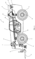
- an embodiment of the teachings includes a working machine 1 which may be a load handling machine.
- the load handling machine is a telescopic handler.
- the working machine 1 may be a skid-steer loader, a compact track loader, a wheel loader, or a telescopic wheel loader, a slew excavator, a backhoe loader, a dumper or a tractor for example.
- Such machines may generally be denoted as off-highway working machines. All such machines include a hydraulic fluid circuit for performing working operations such as moving a working arm of a loader or excavator; tipping a skip of a dumper; or lifting or powering an implement of a tractor.
- the machine 1 includes a machine body 2 which may include a structure to accommodate a machine operator, for example, an enclosed operator's cab from which an operator can operate the machine 1, the working environment in which can be separate from its surroundings.
- the machine may have an open canopy structure (not shown) for the operator.
- the machine 1 has a ground engaging propulsion structure comprising a first axle A 1 and a second axle A 2 , each axle being coupled to a pair of wheels (two wheels 4, 5 are shown in figure 1 with one wheel 4 connected to the first axle A 1 and one wheel 5 connected to the second axle A 2 ).
- the first axle A 1 may be a front axle and the second axle A 2 may be a rear axle.
- One or both of the axles A 1 , A 2 may be coupled to a motor M (see Figure 2 discussed below) which is configured to drive movement of one or both pairs of wheels 4, 5.
- the wheels may contact a ground surface H and rotation of the wheels 4, 5 may cause movement of the machine with respect to the ground surface.
- the ground engaging propulsion structure may comprise tracks.
- drive transmission may not be operated by the motor via a direct mechanical linkage, but instead the motor drives a hydraulic pump, which subsequently provides traction via one or more hydraulic motors that are drivingly connected to the wheels or tracks.
- At least one of the first and second axles A 1 , A 2 is coupled to the machine body 2 by a pivot joint (not shown) located at substantially the centre of the axle such that the axle can rock about a longitudinal axis of the machine 1 - thus, improving traction and stability of the machine 1 when moving across uneven ground. It will be appreciated that this effect can be achieved in other known manners.
- a load handling apparatus 6, 7 is coupled to the machine body 2.
- the load handling apparatus 6, 7 may be mounted by a mount 9 to the machine body 2.
- the load handling apparatus 6, 7 includes a working arm 6, 7.
- the working arm 6, 7 may be a telescopic arm having a first section 6 connected to the mount 9 and a second section 7 which is telescopically fitted to the first section 6.
- the second section 7 of the working arm 6, 7 is telescopically moveable with respect to the first section 6 such that the working arm 6, 7 can be extended and retracted. Movement of the first section 6 with respect to the second section 7 of the working arm 6, 7 may be achieved by use of an extension actuator 8 which may be a double acting hydraulic linear actuator.
- the working arm 6, 7 may include a plurality of sections: for example, the working arm 6, 7 may comprise two, three, four or more sections. Each arm section may be telescopically fitted to at least one other section.
- the working arm 6, 7 can be moved with respect to the machine body 2 and the movement is preferably, at least in part, rotational movement about the mount 9 (about pivot B of the working arm 6, 7).
- the rotational movement is about a substantially transverse axis of the machine 1, the pivot B being transversely arranged.
- Rotational movement of the working arm 6, 7 with respect to the machine body 2 is, in an embodiment, achieved by use of at least one lifting actuator 10 coupled, at one end, to the first section 6 of the working arm 6, 7 and, at a second end, to the machine body 2.
- the lifting actuator 10 is a double acting hydraulic linear actuator, but may alternatively be single acting. In some embodiments, the lifting actuator is an electric linear actuator.
- a load handling implement 11 may be located at a distal end of the working arm 6, 7.
- the load handling implement 11 may include a fork-type implement which may be rotatable with respect to the working arm 6, 7 about a pivot D, this pivot also being transversely arranged. Other implements may be fitted such as shovels, grabs etc. Movement of the load handling implement 11 may be achieved by use of a double acting linear hydraulic actuator (not shown) coupled to the load handling implement 11 and the distal end of the section 7 of the working arm 6, 7.
- the operator cab 3 has a fixed angular orientation with respect to the front and/or rear axles A 1 and A 2 .
- the working machine 1 further comprises a cabin climate control assembly 36 located in the cabin 3.
- the cabin climate control assembly 36 may, dependent on the machine specification and the climate in which it is intended to operate include just a cabin heater or a cabin heater and cabin cooler.
- the working machine 1 of Figure 1 also includes an outside heat exchange assembly 38 that is mounted to the rear of the cabin 3, and is also discussed in more detail below.
- the outside heat exchanger may be mounted in other location on the working machine 1.
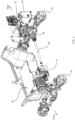
- the working machine 1 is an electric working machine having an electric energy storage unit 20 for providing electrical power to the working machine 1.
- the electrical energy storage unit comprises batteries, but in other embodiments may utilise capacitors or a combination of batteries and capacitors; or other storage technologies.
- the working machine may be a "hybrid" working machine in which an internal combustion engine (ICE) and electric motors may both supply power to the ground engaging propulsion structure and/or the actuators to displace the working arm(s) 6, 7.
- ICE internal combustion engine
- electric motors may both supply power to the ground engaging propulsion structure and/or the actuators to displace the working arm(s) 6, 7.
- the working machine 1 includes an electric drive motor M coupled to the electric energy storage unit 20 via suitable control electrics (not shown) and configured to drive movement of one or both pairs of wheels 4, 5.
- the motor M is coupled to a driveshaft 28 to drive movement of the wheels 4, 5 via axles A 1 and A 2 .
- the working machine 1 also includes a separate hydraulic pump electric motor 30 configured to drive a hydraulic pump 32 to move the working arms 6, 7, e.g. to actuate the actuators 8, 10.
- the hydraulic motor 30 is positioned proximal the mount 9 of the load handling apparatus 6, 7. In other embodiments, a single motor may provide drive for traction and actuation of a working arm.
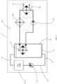
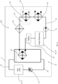
- FIG. 3 a thermal management system 50 of the working machine 1 is illustrated schematically.
- Figure 3 also shows schematically the hydraulic fluid circuit 25 in simplified form filled with hydraulic fluid (e.g. without control valves etc.).
- the hydraulic fluid circuit 25 comprises the hydraulic fluid reservoir 34, supply pipe work 40 to the hydraulic pump 32 and the machine load which in this embodiment comprises the extension actuator 8 and lift actuator 10, as well as other devices in the circuit, which may include an auxiliary circuit to supply hydraulic fluid to an implement mounted to the working arm 6, 7 a power steering actuator and the like.
- the hydraulic fluid Once the hydraulic fluid has been utilised by these devices it is returned to the reservoir 34 via a return pipework 42.
- the thermal management system comprises a liquid/liquid heat exchanger 52 located within the hydraulic fluid reservoir 34 to be immersed within the hydraulic fluid 26.
- the liquid/liquid heat exchanger 52 is connected to a circuit 54 of the thermal management system 50 that is filled with a suitable working liquid such as ethylene-glycol and that is circulated by means of a coolant pump 56 to a liquid/gas heat exchanger 58 that forms part of the cabin climate control assembly 36.
- the circuit 54 then returns the coolant to the liquid/liquid heat exchanger 58.
- the cabin climate control assembly also comprises a fan 60 that blows air over the liquid/gas heat exchanger 58 and through ducts (not shown) into the operator space of the cabin 3.
- a heating element 62 is also immersed within the hydraulic fluid 26 in the hydraulic fluid reservoir 34. Both the coolant pump 56 and the heating element 62 are, in this embodiment, electrically powered. Electrical power may be provided either or from an external power source e.g. mains electrical power via a charger (not shown) or from the electrical energy storage unit 20.
- an external power source e.g. mains electrical power via a charger (not shown) or from the electrical energy storage unit 20.
- the hydraulic fluid 26 is desirable to be within an optimal temperature range that is typically above ambient temperature, e.g. a temperature range of 40-60°C. At this temperature, the viscosity of the hydraulic fluid is reduced and therefore frictional losses as it circulates within the circuit 25 are reduced. Additionally, wear on the valves and other components within the circuit 25 may be reduced at this temperature. Temperatures above this range may however cause damage to components in the circuit 25 or sub-optimal performance and this is also undesirable.
- the temperature When the working machine 1 has been inactive for a period of time (e.g. overnight) in most operating environments, the temperature will be below this desirable range and it will take a period of time for the oil to reach this range (as a result of frictional effects as it circulates) dependent upon ambient temperatures and the intensity with which the machine is operated. In the intervening period, the operational efficiency of the machine is reduced. In some circumstances where the working arms are not operated intensively, the temperature may not achieve the desired range. Further, if the machine has been operating intensively for an extended period of time it is possible that the hydraulic fluid exceeds the desirable temperature range, which may also be undesirable for the reasons stated above.
- the present inventors have recognised that at the same time, there may be a demand for heat to be supplied to the operator cabin to improve operator comfort.
- the present inventors have recognised that the usage of electrical power supplied from the electrical energy storage unit 20 in such circumstances makes inefficient usage of this limited resource when a supply of heat energy may already be available from the hydraulic fluid 26.
- the thermal management system 50 enables the coolant to be circulated around the circuit 54, drawing heat from the hydraulic fluid 26 in the reservoir 34 and supplying it to the liquid/gas heat exchanger 58 in the cabin climate control assembly 36.
- electrical power is required to run the coolant pump 56, this requirement is significantly lower than the energy required to heat an electrical heating element specifically to heat the cabin 3.
- the thermal management system 50 may simultaneously enable the hydraulic fluid to be kept within a desirable operating temperature range and also maintain the cabin temperature at a desirable level for an operator.
- the heating element 62 may be used to pre-heat the hydraulic fluid 26. Whilst the heating element 62 is electrically powered, such pre-heating may occur whilst the working machine 1 is placed onto charge overnight. This means that the electrical power is not supplied from the electrical energy storage unit 20 on the working machine, which would otherwise reduce the electrical energy available to the working machine for performing working operations.
- the heating element 62 may be controlled in such a way as to heat the hydraulic fluid to a higher temperature than may otherwise be required in anticipation of some of said heat being supplied to the cabin climate control assembly 36 immediately upon vehicle operation or to preheat the cabin 3 before the operator enters it.
- liquid/liquid heat exchanger 52 may be placed in the return pipe work 42 rather than within the hydraulic fluid reservoir 44. Such an arrangement may still allow heat to be efficiently recovered from the hydraulic fluid 26.
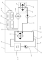
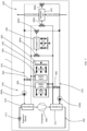
- thermo management system 150 a variant of the thermal management system of Figure 3 is illustrated and denoted by the reference 150.
- This embodiment differs in that the heating element 162 is positioned so as to heat the coolant within the circuit 54 of the thermal management system 150.
- Ethylene-glycol and other similar coolant fluids have a specific heat capacity that is greater than that of hydraulic fluid, in the case of ethylene-glycol approximately 40% more. Accordingly, in certain machine installations it may be advantageous to provide the heat energy to the coolant since a greater amount of energy can thereby be held within the system when it is pre-heated.
- the thermal management system 50 prime operates in a similar way to that of the first embodiment.
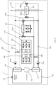
- FIG. 5 illustrates a further embodiment of the present teachings in which further components of the working machine 1, namely power electronics components such as the electrical energy storage unit 20, motors M,30, a charger 44 and an AC/DC inverter 46 are also included within the thermal management system 250.
- power electronics components such as the electrical energy storage unit 20, motors M,30, a charger 44 and an AC/DC inverter 46 are also included within the thermal management system 250.
- these components either operate at an improved efficiency within a particular temperature range, or risk damage by being operated at a temperature above an upper limit.
- the present inventors have found that the batteries of the electrical energy storage unit 20 of the present embodiment operate optimally at a temperature range of around 20-30°C and if the temperature exceeds 60°C operation of the machine will be stopped since this would otherwise risk the safe usage thereof.
- the electric motors M and 30 may suffer temporary or permanent damage if operated above around 120-130°C for example.
- the inclusion within the circuit 54 downstream of the heating element 162 and upstream of the liquid/liquid heat exchanger 52 means that the heating element 162 may be utilised to condition or pre-heat the battery 20 when the machine is utilised in cold climates, but also may allow heat energy to be withdrawn from these components if they are above a desirable operating temperature.
- each of the components may be provided in parallel rather than in series with a suitable valve arrangement to allow the coolant to flow past that particular component if heating or cooling is required or to bypass that component if it is within a suitable operating temperature range.
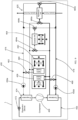
- FIG. 6 illustrates another embodiment of the thermal management system denoted 350.
- the battery 20 and the power electronics 44, 46 are located downstream of the liquid/liquid heat exchanger 52 but notably the thermal management system 350 further includes an auxiliary heat exchanger 64 in series with the liquid/gas heat exchanger 58 of the cabin climate control assembly 36.
- the auxiliary heat exchanger 64 is a further liquid/liquid heat exchanger and is supplied with chilled coolant.
- the coolant may be supplied from a separate cooling circuit (not shown). This permits the cooling of the hydraulic fluid 26 and optionally the battery 20 and power electronics 44, 46 to occur even if heating of the cabin 3 is not required. Ultimately, the heat is expelled to the surroundings of the working machine.
- liquid/liquid auxiliary heat exchanger 64 may be replaced by a liquid/gas heat exchanger e.g. as part of the outside heat exchanger assembly 38 depicted in Figure 1 .
- a liquid/gas heat exchanger may be associated with a fan.
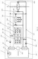
- FIGS 7-10 illustrate a further embodiment of the thermal management system denoted 450 which is more complex than that of the embodiment of Figures 3-6 .
- the thermal management system of this embodiment uses a heat pump arrangement coupled to separate cooling 476 and heating 478 coolant circuits that use valves to selectively switch heat exchange's into either the cooling or the heating circuit.
- the principle of utilising the hydraulic fluid as a possible medium for storing heat energy remains.
- the thermal management system utilises a Carnot cycle heat pump.
- the heat pump comprises a refrigerant circuit 466 that has a compressor 468 in series with a condenser 470, expansion device 472 and evaporator 474.
- the circuit 466 is a closed loop and contains a suitable refrigerant such as R134a or R1234yf.
- the thermal management system 450 also includes the cooling circuit 476 and the heating circuit 478.
- a heat transfer fluid or coolant such as water-ethylene-glycol mix may be used in both the heating and cooling circuit 476, 478.
- Both the heating and cooling circuits comprise pumps 456a and 456b to circulate the coolant around the circuit.
- the cooling circuit 476 is connected to the evaporator 474 and the heating circuit 478 is connected to the condenser 470 such that heat energy may be transferred from the cooling circuit to the heating circuit via the refrigerant circuit 466.
- the cooling circuit 476 is selectively connected to a cabin cooler heat exchanger 480 via a flow control valve 482.
- the cooling circuit is also connected to an outside heat exchanger 464 by first and second three way flow control valve arrangements 484a and 484b.
- the cooling circuit 476 is connected to the hydraulic oil heat exchanger 452 via two further three way flow control valve arrangements 486a and 486b.
- the third port of the three way flow control valve arrangements 484a, 484b, 486a and 486b are connected to the heating circuit 478 such that the three way flow control valve arrangements can switch to the flow of either the cooling circuit 476 or heating circuit 478 as is required.
- the heating circuit 478 is also selectively connected to a cabin heater 458 via a further flow control valve 488.
- the cabin cooler 480 and heater 458 are both, in this embodiment, provided as part of a cabin climate control assembly 436 that also includes a fan 460 that blows outside air past both the cabin cooler and cabin heater 480 and 458 and into the cabin via suitable vents in order to provide for cabin heating or cooling as required.
- the cabin climate control assembly 436 also allows air within the cabin to be recirculated through the cabin cooler 480 or heater 458 in certain embodiments.
- the thermal management system 450 seeks to attain a temperature of hydraulic fluid that is within the desirable temperature range to achieve an optimal viscosity whilst also providing a comfortable environment in the cabin 3 for the operator, without undue use of electrical power from the electrical energy storage unit 20.
- the thermal management system 450 is operating with heat energy being absorbed by the refrigerant circuit 466 via the following heat transfer process: Heat energy in the hydraulic fluid flowing in the hydraulic flowing circuit 425 is transferred to the cooling circuit 476 via the hydraulic oil heat exchanger 452 and from ambient air via the outside heat exchanger 464. This heat energy is then transferred from the cooling circuit 476 to the refrigerant circuit 466 via the evaporator 474 and the refrigerant circuit then transfers this heat to the cabin heater via the condenser 470 and the heating circuit 478.
- the fan 460 blows outside air over the cabin heater 458 to raise the temperature within the cabin 3. It can be seen that the flow control valve 482 is closed so that the cabin cooler 480 is inoperative.
- the rate of coolant flow through the hydraulic oil heat exchanger 452 is metered to control the rate of heat rejection from the hydraulic fluid, with any shortfall in the heat required to be transferred to the cabin heater being supplied by the outside heat exchanger 464.
- FIG 8 illustrates the thermal management system 450 operating in a different mode which reflects a situation in which the working machine is operating in a high ambient temperature and the hydraulic fluid and the cabin simultaneously require cooling. Accordingly, in this situation heat energy is absorbed by the refrigerant circuit 466 via the transfer of heat energy from the hydraulic fluid in the hydraulic fluid circuit 425 to the refrigerant circuit via the cooling circuit 476 and evaporator 474. Simultaneously, heat energy is also transferred from the cabin to the evaporator 474 via the cabin cooler 480.
- the thermal management system is operating in a mode to reflect a situation where, for example, a pre conditioning of the hydraulic fluid and cabin air temperature is required before operation of the working machine 1, or the working machine has just started operating from a cold start and the operator requires the cabin 3 to be heated and at the same time the hydraulic oil in the hydraulic circuit 425 is lower than the target temperature range. Consequently, heat energy is absorbed by the refrigerant circuit 466 via a heat transfer process that takes heat energy from the outside air to the cooling circuit 476 via the outside heat exchanger 464 and then into the refrigerant circuit 466 via the evaporator 474.
- This heat energy is then transferred to the hydraulic fluid in the hydraulic fluid circuit 425 and to the cabin 3 via the refrigerant circuit 466 to the condenser 470 and then into the heating circuit 478 which has its flow control valves set to allow the flow of heated coolant into both the cabin heater 458 and the hydraulic oil heat exchanger 452.
- the thermal management system 450 is set to reflect a situation where the ambient temperature is relatively warm and the operator has requested cooling within the cabin 3 and simultaneously the machine 1 is operating on a light duty cycle such that the natural frictional losses due to flow of hydraulic fluid around the hydraulic fluid circuit 425 is not capable of maintaining the temperature of the hydraulic fluid at the desirable temperature range and therefore some heating of the hydraulic oil is also required.
- heat energy is absorbed by the refrigerant circuit 466 via the cabin air to the cooling circuit via the cabin cooler 480 and to the refrigerant circuit 466 via the cooling circuit 476 and evaporator 474.
- This heat energy is then rejected to the hydraulic fluid and to the outside air by way of its transfer to the condenser via the refrigerant circuit 466 and from the condenser to the heating circuit 478 and then into both the hydraulic oil heat exchanger 452 and the outside heat exchanger 464.
- the rate of flow of heated coolant into the hydraulic oil heat exchanger may be metered to ensure the temperature of the hydraulic oil is maintained within the target temperature range, with the remaining flow and excess heat energy being expelled to the outside air via the outside heat exchanger 464.
- the thermal management system 450 may be switched via the opening and closing of the flow control valves to efficiently provide and remove heat energy to the cabin 3 and or the hydraulic fluid circuit 425 as required and to remove heat energy from the cabin 3 and the hydraulic fluid circuit 425 as required, thereby ensuring a pleasant environment for the working machine operator and the hydraulic fluid being utilised within the desirable temperature range for efficient movement of the working arm 6, 7.
- thermal management system may also be adapted to supply or remove heat energy to the batteries and power electronics by adding the suitable further valves and heat exchange's to the system of figures 7-10 .
- other forms of heat pumps may be utilized such as magnets- Caloric, Peltier, Baro-Caloric, Elasto-Caloric and Electro-Caloric.
Landscapes
- Engineering & Computer Science (AREA)
- Mechanical Engineering (AREA)
- Physics & Mathematics (AREA)
- General Engineering & Computer Science (AREA)
- Thermal Sciences (AREA)
- Chemical & Material Sciences (AREA)
- Mining & Mineral Resources (AREA)
- Civil Engineering (AREA)
- Structural Engineering (AREA)
- Fluid Mechanics (AREA)
- Analytical Chemistry (AREA)
- Combustion & Propulsion (AREA)
- Life Sciences & Earth Sciences (AREA)
- Sustainable Development (AREA)
- Sustainable Energy (AREA)
- Air-Conditioning For Vehicles (AREA)
- Power Engineering (AREA)
- Operation Control Of Excavators (AREA)
- Transportation (AREA)
- Fluid-Pressure Circuits (AREA)
Applications Claiming Priority (2)
| Application Number | Priority Date | Filing Date | Title |
|---|---|---|---|
| GB1910496.7A GB2585908B (en) | 2019-07-23 | 2019-07-23 | Working Machine |
| EP20186805.6A EP3770338B1 (fr) | 2019-07-23 | 2020-07-20 | Machine de travail |
Related Parent Applications (1)
| Application Number | Title | Priority Date | Filing Date |
|---|---|---|---|
| EP20186805.6A Division EP3770338B1 (fr) | 2019-07-23 | 2020-07-20 | Machine de travail |
Publications (2)
| Publication Number | Publication Date |
|---|---|
| EP4317711A2 true EP4317711A2 (fr) | 2024-02-07 |
| EP4317711A3 EP4317711A3 (fr) | 2024-04-17 |
Family
ID=67839734
Family Applications (3)
| Application Number | Title | Priority Date | Filing Date |
|---|---|---|---|
| EP20186804.9A Active EP3770337B1 (fr) | 2019-07-23 | 2020-07-20 | Machine de travail |
| EP20186805.6A Active EP3770338B1 (fr) | 2019-07-23 | 2020-07-20 | Machine de travail |
| EP23208373.3A Pending EP4317711A3 (fr) | 2019-07-23 | 2020-07-20 | Machine de travail |
Family Applications Before (2)
| Application Number | Title | Priority Date | Filing Date |
|---|---|---|---|
| EP20186804.9A Active EP3770337B1 (fr) | 2019-07-23 | 2020-07-20 | Machine de travail |
| EP20186805.6A Active EP3770338B1 (fr) | 2019-07-23 | 2020-07-20 | Machine de travail |
Country Status (3)
| Country | Link |
|---|---|
| US (2) | US11987130B2 (fr) |
| EP (3) | EP3770337B1 (fr) |
| GB (2) | GB2585908B (fr) |
Families Citing this family (10)
| Publication number | Priority date | Publication date | Assignee | Title |
|---|---|---|---|---|
| CN111765796B (zh) * | 2020-07-21 | 2025-03-07 | 广汽本田汽车有限公司 | 循环冷却系统 |
| CN111755776B (zh) * | 2020-08-03 | 2025-08-29 | 上海三一重机股份有限公司 | 热管理系统及电动液压挖掘机 |
| EP4265855A4 (fr) * | 2020-12-17 | 2024-12-11 | Kubota Corporation | Machine de travail |
| US12024860B2 (en) * | 2021-02-18 | 2024-07-02 | Deere & Company | Preheating intelligence for electric-hydraulic work vehicles |
| CN113442679B (zh) * | 2021-07-28 | 2022-12-09 | 江苏汇智高端工程机械创新中心有限公司 | 一种工程机械及集成热管理系统 |
| CN113700704B (zh) * | 2021-08-10 | 2024-04-16 | 天良智能设备(上海)股份有限公司 | 一种高温杀菌机的液压油路风冷系统 |
| CN114670247B (zh) * | 2022-04-20 | 2023-12-08 | 江苏徐工工程机械研究院有限公司 | 破拆机器人的散热系统和破拆机器人 |
| EP4353908A1 (fr) * | 2022-10-12 | 2024-04-17 | Joseph Vögele AG | Engin de construction de routes avec pompe à chaleur |
| US20240401617A1 (en) * | 2023-06-01 | 2024-12-05 | Cnh Industrial America Llc | Systems and methods for recovering and utilizing waste energy in a work vehicle |
| JP2025030692A (ja) * | 2023-08-24 | 2025-03-07 | 株式会社クボタ | 作業機 |
Family Cites Families (26)
| Publication number | Priority date | Publication date | Assignee | Title |
|---|---|---|---|---|
| GB1563701A (en) * | 1975-08-16 | 1980-03-26 | Massey Ferguson Services Nv | Heating systeme for vehicles |
| US4192456A (en) * | 1978-08-21 | 1980-03-11 | Harnischfeger Corporation | Heating system for machine operator's cab |
| DE2928999A1 (de) * | 1979-07-18 | 1981-02-12 | Kloeckner Humboldt Deutz Ag | Vorrichtung zur nutzung der erwaermten druckfluessigkeit der arbeitshydraulik eines kraftfahrzeugs |
| US4352456A (en) * | 1980-06-09 | 1982-10-05 | J. I. Case Company | Cab heating system |
| EP0543606B1 (fr) * | 1991-11-18 | 1996-10-16 | Sanden Corporation | Procédé et dispositif de climatisation de voitures |
| US5697546A (en) * | 1993-04-30 | 1997-12-16 | Cicioni; Albert Brian | Method of forming a compact hydraulic radiator for use in construction equipment and fabrication thereof |
| DE19609048C2 (de) * | 1996-03-08 | 1998-04-16 | Daimler Benz Ag | Heizungs- und Klimatisierungseinrichtung für Kraftfahrzeuge |
| JPH10119552A (ja) * | 1996-10-21 | 1998-05-12 | Toyota Autom Loom Works Ltd | 車両用暖房装置 |
| SE9800619L (sv) * | 1998-02-27 | 1999-03-22 | Volvo Wheel Loaders Ab | Kyl- och värmesystem |
| US6695743B2 (en) * | 2001-09-13 | 2004-02-24 | Toyota Jidosha Kabushiki Kaisha | Vehicular lockup clutch-equipped transmission control apparatus and control method thereof |
| KR100665112B1 (ko) * | 2004-10-15 | 2007-01-04 | 볼보 컨스트럭션 이키프먼트 홀딩 스웨덴 에이비 | 중장비 운전실의 난방장치 |
| JP5271500B2 (ja) * | 2007-03-19 | 2013-08-21 | 日立建機株式会社 | バッテリ駆動式建設機械 |
| JP2009274462A (ja) * | 2008-01-16 | 2009-11-26 | Caterpillar Japan Ltd | 空調装置 |
| JP5462731B2 (ja) * | 2010-06-28 | 2014-04-02 | キャタピラー エス エー アール エル | 建設機械の作動油予熱機構と予熱方法 |
| DE202010011010U1 (de) * | 2010-08-04 | 2010-11-04 | Bucyrus Hex Gmbh | Hydraulische Vorwärmeeinrichtung für Hydraulikölkühler in einem Großhydraulikbagger |
| DE102013102267A1 (de) * | 2013-03-07 | 2014-09-11 | Still Gmbh | Heizvorrichtung für eine mobile Arbeitsmaschine |
| GB2529162B (en) | 2014-08-11 | 2017-11-08 | Jaguar Land Rover Ltd | A vehicle arrangement |
| DE102014112632B4 (de) * | 2014-09-02 | 2024-11-07 | Linde Material Handling Gmbh | Batterieelektrisch betriebenes Flurförderzeug mit Kabinenheizung |
| DE102014119463A1 (de) * | 2014-12-22 | 2016-06-23 | Still Gesellschaft Mit Beschränkter Haftung | Heizvorrichtung für eine mobile Arbeitsmaschine |
| JP6587538B2 (ja) * | 2015-12-25 | 2019-10-09 | 日立建機株式会社 | ハイブリッド式建設機械 |
| CN205895776U (zh) * | 2016-07-28 | 2017-01-18 | 泸州三联工程机械有限公司 | 汽车起重机液压油箱的介质温度调节系统 |
| FR3057494B1 (fr) * | 2016-10-13 | 2019-07-26 | Hutchinson | Installation de conditionnement thermique d'un habitacle et/ou d'au moins un organe d'un vehicule automobile |
| CN106480921A (zh) * | 2016-11-16 | 2017-03-08 | 杭州蓝力电动科技有限公司 | 一种电动工程机械的热管理系统 |
| US10259291B2 (en) * | 2017-08-04 | 2019-04-16 | Caterpillar Inc. | Temperature control system for machine and method of operating same |
| US20220134843A1 (en) * | 2020-10-30 | 2022-05-05 | Cnh Industrial America Llc | Cab heating system for an electric work vehicle |
| GB2608366B (en) * | 2021-06-25 | 2024-11-27 | Perkins Engines Co Ltd | Thermal management of an electric work vehicle |
-
2019
- 2019-07-23 GB GB1910496.7A patent/GB2585908B/en active Active
-
2020
- 2020-03-31 GB GB2004772.6A patent/GB2585970B/en active Active
- 2020-07-20 EP EP20186804.9A patent/EP3770337B1/fr active Active
- 2020-07-20 EP EP20186805.6A patent/EP3770338B1/fr active Active
- 2020-07-20 EP EP23208373.3A patent/EP4317711A3/fr active Pending
- 2020-07-23 US US16/937,571 patent/US11987130B2/en active Active
- 2020-07-23 US US16/937,559 patent/US12421693B2/en active Active
Also Published As
| Publication number | Publication date |
|---|---|
| EP4317711A3 (fr) | 2024-04-17 |
| EP3770337B1 (fr) | 2025-04-16 |
| US11987130B2 (en) | 2024-05-21 |
| EP3770337A1 (fr) | 2021-01-27 |
| GB2585970A (en) | 2021-01-27 |
| EP3770338B1 (fr) | 2023-11-08 |
| GB202004772D0 (en) | 2020-05-13 |
| GB2585970B (en) | 2023-07-12 |
| GB2585908A (en) | 2021-01-27 |
| EP3770338C0 (fr) | 2023-11-08 |
| US20210023907A1 (en) | 2021-01-28 |
| US12421693B2 (en) | 2025-09-23 |
| US20210023950A1 (en) | 2021-01-28 |
| GB2585908B (en) | 2023-08-23 |
| EP3770338A1 (fr) | 2021-01-27 |
| GB201910496D0 (en) | 2019-09-04 |
Similar Documents
| Publication | Publication Date | Title |
|---|---|---|
| EP3770338B1 (fr) | Machine de travail | |
| US11688903B2 (en) | Cooling modes to manage a high voltage battery for a vehicle | |
| KR102390858B1 (ko) | 하이브리드식 작업 기계 | |
| CN103140634B (zh) | 混合动力式作业机的冷却系统 | |
| US20240034195A1 (en) | Powertrain for a work machine, method for operating the powertrain, and work machine | |
| CN104110417B (zh) | 改进的使用液压风扇反转的液压流体加热 | |
| CN106795818A (zh) | 混合动力式工程机械 | |
| US20220134843A1 (en) | Cab heating system for an electric work vehicle | |
| US11318861B2 (en) | Coolant system for a vehicle | |
| DE102011012723A1 (de) | Kühlsystem für eine mobile Arbeitsmaschine | |
| GB2591310A (en) | Thermal management of an electric machine or vehicle | |
| WO2010019527A2 (fr) | Systèmes et procédés d'alimentation d'accessoires dans des véhicules entraînés par moteur à l'aide d'unités d'alimentation de moteur auxiliaires | |
| EP4155142B1 (fr) | Système de gestion d'énergie de véhicule, véhicule comprenant un tel système de gestion d'énergie de véhicule, et procédé de commande d'un système de gestion d'énergie de véhicule | |
| US12139886B2 (en) | Integrated vehicle and battery thermal management of an electric excavator | |
| CN111356808B (zh) | 用于工程机械的驱动系统和用于控制该驱动系统的方法 | |
| US20240401617A1 (en) | Systems and methods for recovering and utilizing waste energy in a work vehicle | |
| US12103401B2 (en) | Braking system and method of controlling such a braking system | |
| AU2025267763A1 (en) | Mobile work machine | |
| WO2025069648A1 (fr) | Engin de chantier électrique | |
| KR20260052975A (ko) | 전동식 작업 기계 | |
| WO2025057896A1 (fr) | Engin de chantier entraîné par batterie | |
| JP2025148071A (ja) | 作業機械 |
Legal Events
| Date | Code | Title | Description |
|---|---|---|---|
| PUAI | Public reference made under article 153(3) epc to a published international application that has entered the european phase |
Free format text: ORIGINAL CODE: 0009012 |
|
| STAA | Information on the status of an ep patent application or granted ep patent |
Free format text: STATUS: REQUEST FOR EXAMINATION WAS MADE |
|
| 17P | Request for examination filed |
Effective date: 20231107 |
|
| AC | Divisional application: reference to earlier application |
Ref document number: 3770338 Country of ref document: EP Kind code of ref document: P |
|
| AK | Designated contracting states |
Kind code of ref document: A2 Designated state(s): AL AT BE BG CH CY CZ DE DK EE ES FI FR GB GR HR HU IE IS IT LI LT LU LV MC MK MT NL NO PL PT RO RS SE SI SK SM TR |
|
| REG | Reference to a national code |
Ref country code: DE Ref legal event code: R079 Free format text: PREVIOUS MAIN CLASS: F15B0021042700 Ipc: E02F0009200000 |
|
| PUAL | Search report despatched |
Free format text: ORIGINAL CODE: 0009013 |
|
| AK | Designated contracting states |
Kind code of ref document: A3 Designated state(s): AL AT BE BG CH CY CZ DE DK EE ES FI FR GB GR HR HU IE IS IT LI LT LU LV MC MK MT NL NO PL PT RO RS SE SI SK SM TR |
|
| RIC1 | Information provided on ipc code assigned before grant |
Ipc: F15B 21/0427 20190101ALI20240313BHEP Ipc: F15B 21/0423 20190101ALI20240313BHEP Ipc: F15B 21/04 20190101ALI20240313BHEP Ipc: B60H 1/03 20060101ALI20240313BHEP Ipc: F15B 21/042 20190101ALI20240313BHEP Ipc: B60H 1/00 20060101ALI20240313BHEP Ipc: E02F 9/22 20060101ALI20240313BHEP Ipc: E02F 9/20 20060101AFI20240313BHEP |
|
| P01 | Opt-out of the competence of the unified patent court (upc) registered |
Free format text: CASE NUMBER: APP_53/2025 Effective date: 20250102 |
|
| GRAP | Despatch of communication of intention to grant a patent |
Free format text: ORIGINAL CODE: EPIDOSNIGR1 |
|
| STAA | Information on the status of an ep patent application or granted ep patent |
Free format text: STATUS: GRANT OF PATENT IS INTENDED |
|
| RIC1 | Information provided on ipc code assigned before grant |
Ipc: E02F 9/20 20060101AFI20260205BHEP Ipc: E02F 9/22 20060101ALI20260205BHEP Ipc: B60H 1/00 20060101ALI20260205BHEP Ipc: F15B 21/042 20190101ALI20260205BHEP Ipc: B60H 1/03 20060101ALI20260205BHEP Ipc: F15B 21/04 20190101ALI20260205BHEP Ipc: F15B 21/0423 20190101ALI20260205BHEP Ipc: F15B 21/0427 20190101ALI20260205BHEP |
|
| GRAS | Grant fee paid |
Free format text: ORIGINAL CODE: EPIDOSNIGR3 |
|
| INTG | Intention to grant announced |
Effective date: 20260219 |