EP4317718A1 - Integrierte resolverlagervorrichtung und verfahren zur herstellung davon - Google Patents
Integrierte resolverlagervorrichtung und verfahren zur herstellung davon Download PDFInfo
- Publication number
- EP4317718A1 EP4317718A1 EP22780001.8A EP22780001A EP4317718A1 EP 4317718 A1 EP4317718 A1 EP 4317718A1 EP 22780001 A EP22780001 A EP 22780001A EP 4317718 A1 EP4317718 A1 EP 4317718A1
- Authority
- EP
- European Patent Office
- Prior art keywords
- stator
- bearing device
- stator core
- type bearing
- holder
- Prior art date
- Legal status (The legal status is an assumption and is not a legal conclusion. Google has not performed a legal analysis and makes no representation as to the accuracy of the status listed.)
- Withdrawn
Links
- 238000004519 manufacturing process Methods 0.000 title claims description 6
- 238000000034 method Methods 0.000 title claims description 6
- 230000002093 peripheral effect Effects 0.000 claims description 39
- 229920003002 synthetic resin Polymers 0.000 claims description 10
- 239000000057 synthetic resin Substances 0.000 claims description 10
- 230000004308 accommodation Effects 0.000 claims description 9
- 229920005989 resin Polymers 0.000 claims description 8
- 239000011347 resin Substances 0.000 claims description 8
- 230000002265 prevention Effects 0.000 claims description 5
- 238000005520 cutting process Methods 0.000 claims description 4
- 239000000463 material Substances 0.000 claims description 3
- 238000001514 detection method Methods 0.000 description 17
- 238000005096 rolling process Methods 0.000 description 13
- 230000004907 flux Effects 0.000 description 7
- XEEYBQQBJWHFJM-UHFFFAOYSA-N Iron Chemical compound [Fe] XEEYBQQBJWHFJM-UHFFFAOYSA-N 0.000 description 6
- 230000007423 decrease Effects 0.000 description 5
- 230000000694 effects Effects 0.000 description 5
- 229910052742 iron Inorganic materials 0.000 description 3
- 239000002184 metal Substances 0.000 description 3
- 229910052751 metal Inorganic materials 0.000 description 3
- 239000012212 insulator Substances 0.000 description 2
- 239000007858 starting material Substances 0.000 description 2
- 239000013585 weight reducing agent Substances 0.000 description 2
- 229910000976 Electrical steel Inorganic materials 0.000 description 1
- 238000001746 injection moulding Methods 0.000 description 1
- 239000011810 insulating material Substances 0.000 description 1
- 238000010030 laminating Methods 0.000 description 1
- 230000000149 penetrating effect Effects 0.000 description 1
- 239000000243 solution Substances 0.000 description 1
Images


Classifications
-
- F—MECHANICAL ENGINEERING; LIGHTING; HEATING; WEAPONS; BLASTING
- F16—ENGINEERING ELEMENTS AND UNITS; GENERAL MEASURES FOR PRODUCING AND MAINTAINING EFFECTIVE FUNCTIONING OF MACHINES OR INSTALLATIONS; THERMAL INSULATION IN GENERAL
- F16C—SHAFTS; FLEXIBLE SHAFTS; ELEMENTS OR CRANKSHAFT MECHANISMS; ROTARY BODIES OTHER THAN GEARING ELEMENTS; BEARINGS
- F16C19/00—Bearings with rolling contact, for exclusively rotary movement
- F16C19/02—Bearings with rolling contact, for exclusively rotary movement with bearing balls essentially of the same size in one or more circular rows
- F16C19/04—Bearings with rolling contact, for exclusively rotary movement with bearing balls essentially of the same size in one or more circular rows for radial load mainly
- F16C19/06—Bearings with rolling contact, for exclusively rotary movement with bearing balls essentially of the same size in one or more circular rows for radial load mainly with a single row or balls
-
- G—PHYSICS
- G01—MEASURING; TESTING
- G01D—MEASURING NOT SPECIALLY ADAPTED FOR A SPECIFIC VARIABLE; ARRANGEMENTS FOR MEASURING TWO OR MORE VARIABLES NOT COVERED IN A SINGLE OTHER SUBCLASS; TARIFF METERING APPARATUS; MEASURING OR TESTING NOT OTHERWISE PROVIDED FOR
- G01D5/00—Mechanical means for transferring the output of a sensing member; Means for converting the output of a sensing member to another variable where the form or nature of the sensing member does not constrain the means for converting; Transducers not specially adapted for a specific variable
- G01D5/12—Mechanical means for transferring the output of a sensing member; Means for converting the output of a sensing member to another variable where the form or nature of the sensing member does not constrain the means for converting; Transducers not specially adapted for a specific variable using electric or magnetic means
- G01D5/14—Mechanical means for transferring the output of a sensing member; Means for converting the output of a sensing member to another variable where the form or nature of the sensing member does not constrain the means for converting; Transducers not specially adapted for a specific variable using electric or magnetic means influencing the magnitude of a current or voltage
- G01D5/20—Mechanical means for transferring the output of a sensing member; Means for converting the output of a sensing member to another variable where the form or nature of the sensing member does not constrain the means for converting; Transducers not specially adapted for a specific variable using electric or magnetic means influencing the magnitude of a current or voltage by varying inductance, e.g. by a movable armature
- G01D5/204—Mechanical means for transferring the output of a sensing member; Means for converting the output of a sensing member to another variable where the form or nature of the sensing member does not constrain the means for converting; Transducers not specially adapted for a specific variable using electric or magnetic means influencing the magnitude of a current or voltage by varying inductance, e.g. by a movable armature by influencing the mutual induction between two or more coils
- G01D5/2046—Mechanical means for transferring the output of a sensing member; Means for converting the output of a sensing member to another variable where the form or nature of the sensing member does not constrain the means for converting; Transducers not specially adapted for a specific variable using electric or magnetic means influencing the magnitude of a current or voltage by varying inductance, e.g. by a movable armature by influencing the mutual induction between two or more coils by a movable ferromagnetic element, e.g. a core
-
- F—MECHANICAL ENGINEERING; LIGHTING; HEATING; WEAPONS; BLASTING
- F16—ENGINEERING ELEMENTS AND UNITS; GENERAL MEASURES FOR PRODUCING AND MAINTAINING EFFECTIVE FUNCTIONING OF MACHINES OR INSTALLATIONS; THERMAL INSULATION IN GENERAL
- F16C—SHAFTS; FLEXIBLE SHAFTS; ELEMENTS OR CRANKSHAFT MECHANISMS; ROTARY BODIES OTHER THAN GEARING ELEMENTS; BEARINGS
- F16C17/00—Sliding-contact bearings for exclusively rotary movement
- F16C17/12—Sliding-contact bearings for exclusively rotary movement characterised by features not related to the direction of the load
- F16C17/22—Sliding-contact bearings for exclusively rotary movement characterised by features not related to the direction of the load with arrangements compensating for thermal expansion
-
- F—MECHANICAL ENGINEERING; LIGHTING; HEATING; WEAPONS; BLASTING
- F16—ENGINEERING ELEMENTS AND UNITS; GENERAL MEASURES FOR PRODUCING AND MAINTAINING EFFECTIVE FUNCTIONING OF MACHINES OR INSTALLATIONS; THERMAL INSULATION IN GENERAL
- F16C—SHAFTS; FLEXIBLE SHAFTS; ELEMENTS OR CRANKSHAFT MECHANISMS; ROTARY BODIES OTHER THAN GEARING ELEMENTS; BEARINGS
- F16C33/00—Parts of bearings; Special methods for making bearings or parts thereof
- F16C33/30—Parts of ball or roller bearings
- F16C33/38—Ball cages
- F16C33/41—Ball cages comb-shaped
- F16C33/412—Massive or moulded comb cages, e.g. snap ball cages
- F16C33/414—Massive or moulded comb cages, e.g. snap ball cages formed as one-piece cages, i.e. monoblock comb cages
- F16C33/416—Massive or moulded comb cages, e.g. snap ball cages formed as one-piece cages, i.e. monoblock comb cages made from plastic, e.g. injection moulded comb cages
-
- F—MECHANICAL ENGINEERING; LIGHTING; HEATING; WEAPONS; BLASTING
- F16—ENGINEERING ELEMENTS AND UNITS; GENERAL MEASURES FOR PRODUCING AND MAINTAINING EFFECTIVE FUNCTIONING OF MACHINES OR INSTALLATIONS; THERMAL INSULATION IN GENERAL
- F16C—SHAFTS; FLEXIBLE SHAFTS; ELEMENTS OR CRANKSHAFT MECHANISMS; ROTARY BODIES OTHER THAN GEARING ELEMENTS; BEARINGS
- F16C33/00—Parts of bearings; Special methods for making bearings or parts thereof
- F16C33/30—Parts of ball or roller bearings
- F16C33/38—Ball cages
- F16C33/44—Selection of substances
-
- F—MECHANICAL ENGINEERING; LIGHTING; HEATING; WEAPONS; BLASTING
- F16—ENGINEERING ELEMENTS AND UNITS; GENERAL MEASURES FOR PRODUCING AND MAINTAINING EFFECTIVE FUNCTIONING OF MACHINES OR INSTALLATIONS; THERMAL INSULATION IN GENERAL
- F16C—SHAFTS; FLEXIBLE SHAFTS; ELEMENTS OR CRANKSHAFT MECHANISMS; ROTARY BODIES OTHER THAN GEARING ELEMENTS; BEARINGS
- F16C33/00—Parts of bearings; Special methods for making bearings or parts thereof
- F16C33/30—Parts of ball or roller bearings
- F16C33/58—Raceways; Race rings
-
- F—MECHANICAL ENGINEERING; LIGHTING; HEATING; WEAPONS; BLASTING
- F16—ENGINEERING ELEMENTS AND UNITS; GENERAL MEASURES FOR PRODUCING AND MAINTAINING EFFECTIVE FUNCTIONING OF MACHINES OR INSTALLATIONS; THERMAL INSULATION IN GENERAL
- F16C—SHAFTS; FLEXIBLE SHAFTS; ELEMENTS OR CRANKSHAFT MECHANISMS; ROTARY BODIES OTHER THAN GEARING ELEMENTS; BEARINGS
- F16C33/00—Parts of bearings; Special methods for making bearings or parts thereof
- F16C33/30—Parts of ball or roller bearings
- F16C33/58—Raceways; Race rings
- F16C33/583—Details of specific parts of races
- F16C33/586—Details of specific parts of races outside the space between the races, e.g. end faces or bore of inner ring
-
- F—MECHANICAL ENGINEERING; LIGHTING; HEATING; WEAPONS; BLASTING
- F16—ENGINEERING ELEMENTS AND UNITS; GENERAL MEASURES FOR PRODUCING AND MAINTAINING EFFECTIVE FUNCTIONING OF MACHINES OR INSTALLATIONS; THERMAL INSULATION IN GENERAL
- F16C—SHAFTS; FLEXIBLE SHAFTS; ELEMENTS OR CRANKSHAFT MECHANISMS; ROTARY BODIES OTHER THAN GEARING ELEMENTS; BEARINGS
- F16C41/00—Other accessories, e.g. devices integrated in the bearing not relating to the bearing function as such
-
- F—MECHANICAL ENGINEERING; LIGHTING; HEATING; WEAPONS; BLASTING
- F16—ENGINEERING ELEMENTS AND UNITS; GENERAL MEASURES FOR PRODUCING AND MAINTAINING EFFECTIVE FUNCTIONING OF MACHINES OR INSTALLATIONS; THERMAL INSULATION IN GENERAL
- F16C—SHAFTS; FLEXIBLE SHAFTS; ELEMENTS OR CRANKSHAFT MECHANISMS; ROTARY BODIES OTHER THAN GEARING ELEMENTS; BEARINGS
- F16C41/00—Other accessories, e.g. devices integrated in the bearing not relating to the bearing function as such
- F16C41/004—Electro-dynamic machines, e.g. motors, generators, actuators
-
- F—MECHANICAL ENGINEERING; LIGHTING; HEATING; WEAPONS; BLASTING
- F16—ENGINEERING ELEMENTS AND UNITS; GENERAL MEASURES FOR PRODUCING AND MAINTAINING EFFECTIVE FUNCTIONING OF MACHINES OR INSTALLATIONS; THERMAL INSULATION IN GENERAL
- F16C—SHAFTS; FLEXIBLE SHAFTS; ELEMENTS OR CRANKSHAFT MECHANISMS; ROTARY BODIES OTHER THAN GEARING ELEMENTS; BEARINGS
- F16C41/00—Other accessories, e.g. devices integrated in the bearing not relating to the bearing function as such
- F16C41/007—Encoders, e.g. parts with a plurality of alternating magnetic poles
-
- G—PHYSICS
- G01—MEASURING; TESTING
- G01D—MEASURING NOT SPECIALLY ADAPTED FOR A SPECIFIC VARIABLE; ARRANGEMENTS FOR MEASURING TWO OR MORE VARIABLES NOT COVERED IN A SINGLE OTHER SUBCLASS; TARIFF METERING APPARATUS; MEASURING OR TESTING NOT OTHERWISE PROVIDED FOR
- G01D3/00—Indicating or recording apparatus with provision for the special purposes referred to in the subgroups
- G01D3/08—Indicating or recording apparatus with provision for the special purposes referred to in the subgroups with provision for safeguarding the apparatus, e.g. against abnormal operation, against breakdown
-
- G—PHYSICS
- G01—MEASURING; TESTING
- G01D—MEASURING NOT SPECIALLY ADAPTED FOR A SPECIFIC VARIABLE; ARRANGEMENTS FOR MEASURING TWO OR MORE VARIABLES NOT COVERED IN A SINGLE OTHER SUBCLASS; TARIFF METERING APPARATUS; MEASURING OR TESTING NOT OTHERWISE PROVIDED FOR
- G01D5/00—Mechanical means for transferring the output of a sensing member; Means for converting the output of a sensing member to another variable where the form or nature of the sensing member does not constrain the means for converting; Transducers not specially adapted for a specific variable
- G01D5/12—Mechanical means for transferring the output of a sensing member; Means for converting the output of a sensing member to another variable where the form or nature of the sensing member does not constrain the means for converting; Transducers not specially adapted for a specific variable using electric or magnetic means
- G01D5/14—Mechanical means for transferring the output of a sensing member; Means for converting the output of a sensing member to another variable where the form or nature of the sensing member does not constrain the means for converting; Transducers not specially adapted for a specific variable using electric or magnetic means influencing the magnitude of a current or voltage
- G01D5/20—Mechanical means for transferring the output of a sensing member; Means for converting the output of a sensing member to another variable where the form or nature of the sensing member does not constrain the means for converting; Transducers not specially adapted for a specific variable using electric or magnetic means influencing the magnitude of a current or voltage by varying inductance, e.g. by a movable armature
-
- H—ELECTRICITY
- H02—GENERATION; CONVERSION OR DISTRIBUTION OF ELECTRIC POWER
- H02K—DYNAMO-ELECTRIC MACHINES
- H02K11/00—Structural association of dynamo-electric machines with electric components or with devices for shielding, monitoring or protection
- H02K11/20—Structural association of dynamo-electric machines with electric components or with devices for shielding, monitoring or protection for measuring, monitoring, testing, protecting or switching
- H02K11/21—Devices for sensing speed or position, or actuated thereby
- H02K11/215—Magnetic effect devices, e.g. Hall-effect or magneto-resistive elements
-
- H—ELECTRICITY
- H02—GENERATION; CONVERSION OR DISTRIBUTION OF ELECTRIC POWER
- H02K—DYNAMO-ELECTRIC MACHINES
- H02K24/00—Machines adapted for the instantaneous transmission or reception of the angular displacement of rotating parts, e.g. synchro, selsyn
-
- H—ELECTRICITY
- H02—GENERATION; CONVERSION OR DISTRIBUTION OF ELECTRIC POWER
- H02K—DYNAMO-ELECTRIC MACHINES
- H02K7/00—Arrangements for handling mechanical energy structurally associated with dynamo-electric machines, e.g. structural association with mechanical driving motors or auxiliary dynamo-electric machines
- H02K7/08—Structural association with bearings
-
- F—MECHANICAL ENGINEERING; LIGHTING; HEATING; WEAPONS; BLASTING
- F16—ENGINEERING ELEMENTS AND UNITS; GENERAL MEASURES FOR PRODUCING AND MAINTAINING EFFECTIVE FUNCTIONING OF MACHINES OR INSTALLATIONS; THERMAL INSULATION IN GENERAL
- F16C—SHAFTS; FLEXIBLE SHAFTS; ELEMENTS OR CRANKSHAFT MECHANISMS; ROTARY BODIES OTHER THAN GEARING ELEMENTS; BEARINGS
- F16C2202/00—Solid materials defined by their properties
- F16C2202/20—Thermal properties
- F16C2202/22—Coefficient of expansion
-
- F—MECHANICAL ENGINEERING; LIGHTING; HEATING; WEAPONS; BLASTING
- F16—ENGINEERING ELEMENTS AND UNITS; GENERAL MEASURES FOR PRODUCING AND MAINTAINING EFFECTIVE FUNCTIONING OF MACHINES OR INSTALLATIONS; THERMAL INSULATION IN GENERAL
- F16C—SHAFTS; FLEXIBLE SHAFTS; ELEMENTS OR CRANKSHAFT MECHANISMS; ROTARY BODIES OTHER THAN GEARING ELEMENTS; BEARINGS
- F16C2226/00—Joining parts; Fastening; Assembling or mounting parts
- F16C2226/10—Force connections, e.g. clamping
- F16C2226/12—Force connections, e.g. clamping by press-fit, e.g. plug-in
-
- F—MECHANICAL ENGINEERING; LIGHTING; HEATING; WEAPONS; BLASTING
- F16—ENGINEERING ELEMENTS AND UNITS; GENERAL MEASURES FOR PRODUCING AND MAINTAINING EFFECTIVE FUNCTIONING OF MACHINES OR INSTALLATIONS; THERMAL INSULATION IN GENERAL
- F16C—SHAFTS; FLEXIBLE SHAFTS; ELEMENTS OR CRANKSHAFT MECHANISMS; ROTARY BODIES OTHER THAN GEARING ELEMENTS; BEARINGS
- F16C2226/00—Joining parts; Fastening; Assembling or mounting parts
- F16C2226/30—Material joints
-
- F—MECHANICAL ENGINEERING; LIGHTING; HEATING; WEAPONS; BLASTING
- F16—ENGINEERING ELEMENTS AND UNITS; GENERAL MEASURES FOR PRODUCING AND MAINTAINING EFFECTIVE FUNCTIONING OF MACHINES OR INSTALLATIONS; THERMAL INSULATION IN GENERAL
- F16C—SHAFTS; FLEXIBLE SHAFTS; ELEMENTS OR CRANKSHAFT MECHANISMS; ROTARY BODIES OTHER THAN GEARING ELEMENTS; BEARINGS
- F16C2226/00—Joining parts; Fastening; Assembling or mounting parts
- F16C2226/30—Material joints
- F16C2226/40—Material joints with adhesive
-
- F—MECHANICAL ENGINEERING; LIGHTING; HEATING; WEAPONS; BLASTING
- F16—ENGINEERING ELEMENTS AND UNITS; GENERAL MEASURES FOR PRODUCING AND MAINTAINING EFFECTIVE FUNCTIONING OF MACHINES OR INSTALLATIONS; THERMAL INSULATION IN GENERAL
- F16C—SHAFTS; FLEXIBLE SHAFTS; ELEMENTS OR CRANKSHAFT MECHANISMS; ROTARY BODIES OTHER THAN GEARING ELEMENTS; BEARINGS
- F16C2226/00—Joining parts; Fastening; Assembling or mounting parts
- F16C2226/50—Positive connections
- F16C2226/52—Positive connections with plastic deformation, e.g. caulking or staking
- F16C2226/54—Positive connections with plastic deformation, e.g. caulking or staking with rivets
-
- F—MECHANICAL ENGINEERING; LIGHTING; HEATING; WEAPONS; BLASTING
- F16—ENGINEERING ELEMENTS AND UNITS; GENERAL MEASURES FOR PRODUCING AND MAINTAINING EFFECTIVE FUNCTIONING OF MACHINES OR INSTALLATIONS; THERMAL INSULATION IN GENERAL
- F16C—SHAFTS; FLEXIBLE SHAFTS; ELEMENTS OR CRANKSHAFT MECHANISMS; ROTARY BODIES OTHER THAN GEARING ELEMENTS; BEARINGS
- F16C2380/00—Electrical apparatus
- F16C2380/26—Dynamo-electric machines or combinations therewith, e.g. electro-motors and generators
Definitions
- the present invention relates to a resolver integrated-type bearing device including a resolver capable of detecting a rotation angle of a rotating shaft.
- PTL 1 discloses a resolver in which a stator provided with a plurality of protrusions on an outer periphery thereof is press-fitted and fixed to a case member formed by stamping, the case member is fixed to a housing by bolts, and the stator can be attached without being affected by strain of the case member.
- PTL 2 discloses a rolling bearing unit equipped with a sensor, in which a stator is press-fitted to an inner peripheral surface of an outer ring of a rolling bearing, and an eccentric cylindrical rotor is provided at a position facing a stator on an outer peripheral surface of an inner ring, and cost reduction and compactness are achieved.
- the stator since the stator is press-fitted and fixed to the case member made of a plate material that is thin enough to allow stamping, the case member may be deformed and the stator may become eccentric. Therefore, a possibility that detection accuracy decreases cannot be eliminated, and there is room for improvement. Further, since the case member is fixed to the housing by bolts in order to prevent creep, there are problems such as an increase in the number of components and an increase in size and weight. Further, according to the rolling bearing unit equipped with the sensor in PTL 2, since the stator is press-fitted and fixed to the inner peripheral surface of the outer ring, depending on a press-fit state, the stator may creep against the outer ring and affect a detection angle.
- the invention has been made in view of the above problems, and an object of the invention is to provide a resolver integrated-type bearing device and a method for manufacturing same in which a stator core of a stator is improved in handleability and detection accuracy.
- the handleability and the detection accuracy of the stator core of the stator can be improved.
- a resolver integrated-type bearing device 10 includes a rolling bearing 20 that rotatably supports a rotating shaft 11 with respect to a housing 50, and a resolver 30 that detects a rotation angle of the rotating shaft 11 of a motor generator used in, for example, a hybrid vehicle.
- the rolling bearing 20 includes an outer ring 21 that is fitted to an inner peripheral surface 51 of the cylindrical housing 50 and has an outer ring raceway 21a formed on an inner peripheral surface thereof, an inner ring 22 that is fitted to an outer peripheral surface of the rotating shaft 11 and has an inner ring raceway 22a formed on an outer peripheral surface thereof, and a plurality of balls 23 that are rolling elements disposed between the outer ring raceway 21a and the inner ring raceway 22a and that are held by a cage 24 (in the present embodiment, a resin crown-shaped cage) in a freely rotatable manner.
- a cage 24 in the present embodiment, a resin crown-shaped cage
- the rolling bearing 20 is not limited to a ball bearing, and may be another type of rolling bearing.
- the resolver 30 includes a rotor 31 that is fixed to the rotating shaft 11 and rotates together with the rotating shaft 11, and a stator 32 that is disposed radially outward of the rotor 31 with a radial gap C therebetween.
- the rotor 31 has a non-circular shape whose outer diameter dimension varies in a circumferential direction such that the radial gap C between the rotor 31 and the stator 32 changes with rotation.
- the stator 32 includes a stator core 34 formed by laminating a plurality of substantially annular silicon steel plates and provided with a plurality of teeth 33 protruding radially inboard on an inner peripheral surface thereof, and coils 36 wound around the teeth 33 of the stator core 34 via insulators 35.
- the insulator 35 is made of an insulating material such as synthetic resin to insulate the tooth 33 from the coil 36.
- a front surface side (right side in FIG. 1 ) of the coil 36 may be covered by a cover 39 having an annular plate shape.
- a terminal block 37 having a substantially rectangular box shape is attached to an outer peripheral surface of the stator core 34 so as to protrude radially outward.
- a plurality of terminals (not shown) connected to the coils 36 of the stator 32 are led out to an outside via the terminal block 37.
- the stator core 34 is fixed to a stator holder 40.
- the stator holder 40 is made of synthetic resin and includes an annular plate portion 42, an annular convex portion 44 protruding from a radially intermediate portion of the annular plate portion 42 on the other side in an axial direction (left side in FIG. 1 ) to the other side in the axial direction, and an annular portion 43 extending from an outer peripheral portion of the annular plate portion 42 on one side in the axial direction (right side in FIG. 1 ) to the one side in the axial direction.
- the annular convex portion 44 is press-fitted into an annular concave portion 21b formed in the inner peripheral surface by cutting out a shoulder portion of the outer ring 21, and the stator holder 40 is integrally fixed to the outer ring 21. Accordingly, the stator core 34 of the stator 32 is integrally attached to the rolling bearing 20 via the stator holder 40.
- the annular concave portion 21b is formed on an opposite side in the axial direction to a circular annular portion of the crown-shaped cage 24 with respect to the ball 23. That is, the resolver 30 is disposed on a pocket opening side of the resin crown-shaped cage 24 via the stator holder 40.
- stator holder 40 is formed with a stator accommodation portion 41 having a substantially L-shaped cross section that accommodates the stator core 34 by a side surface 42a of the annular plate portion 42 on the one side in the axial direction and an inner peripheral surface 43a of the annular portion 43.
- a stator accommodation portion 41 having a substantially L-shaped cross section that accommodates the stator core 34 by a side surface 42a of the annular plate portion 42 on the one side in the axial direction and an inner peripheral surface 43a of the annular portion 43.
- the stator holder 40 is made of synthetic resin and has a coefficient of linear thermal expansion equivalent to that of the stator core 34. Accordingly, even when a temperature of the resolver 30 changes, a fitting state between the stator core 34 and the stator holder 40 changes little, eccentricity of the stator core 34 is prevented to maintain high detection accuracy. Further, when the stator holder 40 is formed by injection molding, other portions attached to the stator holder 40 can be simultaneously molded, and the number of components can be reduced.
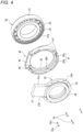
- the stator core 34 is fitted to the stator accommodation portion 41 by clearance fit, centered with respect to the rotor 31, and then fixed to the stator holder 40 by a plurality of rivets 52.
- the rivet 52 is inserted through a rivet hole 34a provided on an outer peripheral side of the stator core 34 and a rivet hole 42b penetrating the annular plate portion 42 in the axial direction from the side surface 42a of the annular plate portion 42 on the one side in the axial direction, and is crimped from both sides, so that the stator core 34 is fixed to the stator holder 40.
- Both side surfaces of the stator holder 40 are provided with radial grooves 47 radially outward corresponding to the rivet holes 42b. Head portions 52a of the crimped rivet 52 are configured so as not to protrude from both side surfaces of the stator holder 40.
- stator core 34 is fitted to the stator accommodation portion 41 by clearance fit and is rivet fastened in a state of being centered with respect to the rotor 31, no radial stress is applied from the stator holder 40 to the stator core 34, and a decrease in accuracy due to the eccentricity of the stator core 34 is prevented.
- the number of rivet holes 34a into which the rivets 52 are inserted is set to 1/N (N: integer) of the number of coils 36, the effect on the magnetic flux can be equalized, which is preferable.
- N integer
- the number of rivet holes 34a is greater than the number of rivets 52.
- the number of rivet holes 34a is calculated on an assumption that the rivet holes 34a are disposed at equal intervals in the circumferential direction without considering a region of the terminal block 37.
- Fixing of the stator core 34 and the stator holder 40 is not limited to the rivet 52, and may be performed by bonding or press-fitting.
- the stator core 34 is fixed to the stator accommodation portion 41 by bonding, similarly to the fixing by the rivet 52, since the stator core 34 and the stator accommodation portion 41 are fitted to each other by clearance fit and are bonded to each other in a state of being centered with respect to the rotor 31, no radial stress is applied from the stator holder 40 to the stator core 34, and a decrease in accuracy due to the eccentricity of the stator core 34 is prevented.
- the stator core 34 is press-fitted into the stator accommodation portion 41, but by making the stator holder 40 made of resin, a radial thickness of the annular portion 43 can be easily increased. Therefore, the annular portion 43 is less likely to be deformed than a thin plate case member formed by stamping in the related art, and the eccentricity of the stator core 34 due to deformation of the annular portion 43 can be prevented. Therefore, a decrease in accuracy due to the eccentricity of the stator core 34 is prevented.
- the outer peripheral surface of the annular portion 43 closely faces the inner peripheral surface 51 of the housing 50, and the inner peripheral surface 43a of the annular portion 43 is positioned radially inward than an outer peripheral surface of the annular convex portion 44, so that the annular portion 43 is formed to have a large radial thickness.
- stator holder 40 is configured to come into contact with the axial side surface 34b of the stator core 34, a component such as a shim for ensuring an axial distance between the stator core 34 and the rolling bearing 20, which is necessary for a case member formed by stamping, is not necessary, and the number of components can be reduced.
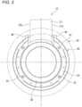
- the stator holder 40 is formed with an open groove 45 having a substantially U-shaped cross section, which is open toward the stator 32, by cutting out a part of a fitting portion in the circumferential direction that is fitted to the outer peripheral surface of the stator core 34.
- An edge portion of the stator holder 40 forming the open groove 45 surrounds both side surfaces 37a and 37b of the terminal block 37 and a side surface 37c on a bearing 20 side. Accordingly, the terminal block 37 of the stator can be made to protrude radially outward, and an axial thickness of the stator 32 can be reduced to contribute to compactness and weight reduction.
- edge portion of the stator holder 40 forming the open groove 45 is formed with a protrusion 46 that protrudes radially outward.
- a part of the housing 50 in the circumferential direction is provided with a notched groove 53 that penetrates in the radial direction and is open to the rolling bearing 20 side and has a U-shape in a top view.
- An edge portion of the housing forming the notched groove 53 comes into contact with a circumferential side surface of the protrusion 46 of the stator holder 40, and the protrusion 46 of the stator holder 40 engages with the notched groove 53 of the housing 50, thereby preventing rotation of the stator holder 40. Therefore, creep of the rolling bearing 20 fixed to the stator holder 40 can be prevented.
- stator holder 40 fixed to the outer ring 21 and the stator core 34 also rotate. Rotation of the stator core 34 directly affects detection accuracy of a detection angle and control of the motor based on the detection angle. In an extreme case, a cable or a connector of the resolver integrated-type bearing device 10 may be broken.
- the invention is not limited to the above embodiment, and can be appropriately modified, improved, or the like.
Landscapes
- Engineering & Computer Science (AREA)
- General Engineering & Computer Science (AREA)
- Mechanical Engineering (AREA)
- Power Engineering (AREA)
- Physics & Mathematics (AREA)
- General Physics & Mathematics (AREA)
- Microelectronics & Electronic Packaging (AREA)
- Transmission And Conversion Of Sensor Element Output (AREA)
Applications Claiming Priority (4)
| Application Number | Priority Date | Filing Date | Title |
|---|---|---|---|
| JP2021062264A JP2022157816A (ja) | 2021-03-31 | 2021-03-31 | レゾルバ一体型軸受装置及びその製造方法 |
| JP2021062265A JP2022157817A (ja) | 2021-03-31 | 2021-03-31 | レゾルバ一体型軸受装置 |
| JP2021062263A JP2022157815A (ja) | 2021-03-31 | 2021-03-31 | レゾルバ一体型軸受装置 |
| PCT/JP2022/011033 WO2022209780A1 (ja) | 2021-03-31 | 2022-03-11 | レゾルバ一体型軸受装置及びその製造方法 |
Publications (2)
| Publication Number | Publication Date |
|---|---|
| EP4317718A1 true EP4317718A1 (de) | 2024-02-07 |
| EP4317718A4 EP4317718A4 (de) | 2024-09-25 |
Family
ID=83456231
Family Applications (1)
| Application Number | Title | Priority Date | Filing Date |
|---|---|---|---|
| EP22780001.8A Withdrawn EP4317718A4 (de) | 2021-03-31 | 2022-03-11 | Integrierte resolverlagervorrichtung und verfahren zur herstellung davon |
Country Status (4)
| Country | Link |
|---|---|
| US (1) | US20240159276A1 (de) |
| EP (1) | EP4317718A4 (de) |
| KR (1) | KR20230150390A (de) |
| WO (1) | WO2022209780A1 (de) |
Cited By (1)
| Publication number | Priority date | Publication date | Assignee | Title |
|---|---|---|---|---|
| EP4585820A4 (de) * | 2022-09-06 | 2025-12-17 | Ntn Toyo Bearing Co Ltd | Lagervorrichtung |
Family Cites Families (12)
| Publication number | Priority date | Publication date | Assignee | Title |
|---|---|---|---|---|
| JPS5870607U (ja) | 1981-11-08 | 1983-05-13 | 田部井土木株式会社 | 日光導入装置 |
| JP4516683B2 (ja) * | 2000-10-19 | 2010-08-04 | 本田技研工業株式会社 | レゾルバの取付構造 |
| JP2004048887A (ja) * | 2002-07-10 | 2004-02-12 | Asmo Co Ltd | ブラシレスモータ |
| JP2006090511A (ja) * | 2004-09-27 | 2006-04-06 | Jtekt Corp | センサ付き転がり軸受装置 |
| DE112011102924T5 (de) * | 2010-09-03 | 2013-07-18 | Ntn Corporation | Lagerbaugruppe mit Rotationssensor |
| JP5870607B2 (ja) * | 2011-02-14 | 2016-03-01 | 株式会社ジェイテクト | レゾルバ及びレゾルバ付き転がり軸受装置 |
| DE102014210014A1 (de) * | 2014-05-26 | 2015-11-26 | Schaeffler Technologies AG & Co. KG | Resolverlager, Resolverstator und Verfahren zu dessen Herstellung |
| CN108348700B (zh) | 2015-10-30 | 2022-04-29 | 强生消费者公司 | 单位剂量无菌气溶胶雾化装置 |
| DE102017103414B3 (de) * | 2017-02-20 | 2018-02-15 | Schaeffler Technologies AG & Co. KG | Resolverlageranordnung |
| JP2021010219A (ja) * | 2019-06-28 | 2021-01-28 | ミネベアミツミ株式会社 | ステータコアの取付構造およびレゾルバ |
| JP2021062264A (ja) | 2021-01-19 | 2021-04-22 | 株式会社藤商事 | 遊技機 |
| JP2021062263A (ja) | 2021-01-19 | 2021-04-22 | 株式会社三洋物産 | 遊技機 |
-
2022
- 2022-03-11 KR KR1020237033656A patent/KR20230150390A/ko not_active Withdrawn
- 2022-03-11 WO PCT/JP2022/011033 patent/WO2022209780A1/ja not_active Ceased
- 2022-03-11 EP EP22780001.8A patent/EP4317718A4/de not_active Withdrawn
- 2022-03-11 US US18/282,936 patent/US20240159276A1/en not_active Abandoned
Cited By (1)
| Publication number | Priority date | Publication date | Assignee | Title |
|---|---|---|---|---|
| EP4585820A4 (de) * | 2022-09-06 | 2025-12-17 | Ntn Toyo Bearing Co Ltd | Lagervorrichtung |
Also Published As
| Publication number | Publication date |
|---|---|
| US20240159276A1 (en) | 2024-05-16 |
| EP4317718A4 (de) | 2024-09-25 |
| KR20230150390A (ko) | 2023-10-30 |
| WO2022209780A1 (ja) | 2022-10-06 |
Similar Documents
| Publication | Publication Date | Title |
|---|---|---|
| EP2487377B1 (de) | Drehgeber und Drehgeber-Wälzlagereinheit | |
| CN104321955B (zh) | 旋转电机 | |
| JP5786642B2 (ja) | ステータ固定構造 | |
| US20210029843A1 (en) | Electronic apparatus | |
| JP5803567B2 (ja) | ステータ固定構造 | |
| US11218042B2 (en) | Rotor for motor | |
| US11204261B2 (en) | Rotational position detection device | |
| CN110495078A (zh) | 马达 | |
| JP4941428B2 (ja) | 車両用回転電機 | |
| US20240159276A1 (en) | Resolver integrated-type bearing device and method for manufacturing same | |
| JP6789000B2 (ja) | 回転電機 | |
| EP2492645A1 (de) | Drehmelder und Drehmelder-Lagereinheit damit | |
| EP3457540A1 (de) | Antriebsvorrichtung | |
| JP2022157817A (ja) | レゾルバ一体型軸受装置 | |
| EP3438485A1 (de) | Lageranordnung, motor und montageverfahren für lageranordnung | |
| JP2024151540A (ja) | 回転センサ一体型軸受 | |
| JP2022157815A (ja) | レゾルバ一体型軸受装置 | |
| CN119563273A (zh) | 电动马达、尤其是散热器风扇马达 | |
| CN116134701B (zh) | 旋转电机以及旋转电机的制造方法 | |
| JP2022157816A (ja) | レゾルバ一体型軸受装置及びその製造方法 | |
| CN118922643A (zh) | 轴承装置 | |
| CN110476332B (zh) | 马达 | |
| EP3457541A1 (de) | Antriebsvorrichtung | |
| JP7765327B2 (ja) | 軸受装置 | |
| JP2026053992A (ja) | 軸受装置 |
Legal Events
| Date | Code | Title | Description |
|---|---|---|---|
| STAA | Information on the status of an ep patent application or granted ep patent |
Free format text: STATUS: THE INTERNATIONAL PUBLICATION HAS BEEN MADE |
|
| PUAI | Public reference made under article 153(3) epc to a published international application that has entered the european phase |
Free format text: ORIGINAL CODE: 0009012 |
|
| STAA | Information on the status of an ep patent application or granted ep patent |
Free format text: STATUS: REQUEST FOR EXAMINATION WAS MADE |
|
| 17P | Request for examination filed |
Effective date: 20230919 |
|
| AK | Designated contracting states |
Kind code of ref document: A1 Designated state(s): AL AT BE BG CH CY CZ DE DK EE ES FI FR GB GR HR HU IE IS IT LI LT LU LV MC MK MT NL NO PL PT RO RS SE SI SK SM TR |
|
| DAV | Request for validation of the european patent (deleted) | ||
| DAX | Request for extension of the european patent (deleted) | ||
| A4 | Supplementary search report drawn up and despatched |
Effective date: 20240822 |
|
| RIC1 | Information provided on ipc code assigned before grant |
Ipc: H02K 11/215 20160101ALI20240817BHEP Ipc: G01D 5/20 20060101ALI20240817BHEP Ipc: H02K 24/00 20060101ALI20240817BHEP Ipc: H02K 7/08 20060101ALI20240817BHEP Ipc: H02K 5/16 20060101ALI20240817BHEP Ipc: F16C 41/00 20060101ALI20240817BHEP Ipc: F16C 33/58 20060101ALI20240817BHEP Ipc: F16C 33/44 20060101ALI20240817BHEP Ipc: F16C 19/06 20060101AFI20240817BHEP |
|
| STAA | Information on the status of an ep patent application or granted ep patent |
Free format text: STATUS: THE APPLICATION HAS BEEN WITHDRAWN |
|
| 18W | Application withdrawn |
Effective date: 20241125 |