EP4317742A1 - Vis sphérique à rangées multiples - Google Patents
Vis sphérique à rangées multiples Download PDFInfo
- Publication number
- EP4317742A1 EP4317742A1 EP22780437.4A EP22780437A EP4317742A1 EP 4317742 A1 EP4317742 A1 EP 4317742A1 EP 22780437 A EP22780437 A EP 22780437A EP 4317742 A1 EP4317742 A1 EP 4317742A1
- Authority
- EP
- European Patent Office
- Prior art keywords
- spiral groove
- nut
- spiral
- row
- spiral grooves
- Prior art date
- Legal status (The legal status is an assumption and is not a legal conclusion. Google has not performed a legal analysis and makes no representation as to the accuracy of the status listed.)
- Granted
Links
Images


Classifications
-
- F—MECHANICAL ENGINEERING; LIGHTING; HEATING; WEAPONS; BLASTING
- F16—ENGINEERING ELEMENTS AND UNITS; GENERAL MEASURES FOR PRODUCING AND MAINTAINING EFFECTIVE FUNCTIONING OF MACHINES OR INSTALLATIONS; THERMAL INSULATION IN GENERAL
- F16H—GEARING
- F16H25/00—Gearings comprising primarily only cams, cam-followers and screw-and-nut mechanisms
- F16H25/18—Gearings comprising primarily only cams, cam-followers and screw-and-nut mechanisms for conveying or interconverting oscillating or reciprocating motions
- F16H25/20—Screw mechanisms
- F16H25/24—Elements essential to such mechanisms, e.g. screws, nuts
-
- F—MECHANICAL ENGINEERING; LIGHTING; HEATING; WEAPONS; BLASTING
- F16—ENGINEERING ELEMENTS AND UNITS; GENERAL MEASURES FOR PRODUCING AND MAINTAINING EFFECTIVE FUNCTIONING OF MACHINES OR INSTALLATIONS; THERMAL INSULATION IN GENERAL
- F16H—GEARING
- F16H25/00—Gearings comprising primarily only cams, cam-followers and screw-and-nut mechanisms
- F16H25/18—Gearings comprising primarily only cams, cam-followers and screw-and-nut mechanisms for conveying or interconverting oscillating or reciprocating motions
- F16H25/20—Screw mechanisms
- F16H25/22—Screw mechanisms with balls, rollers, or similar members between the co-operating parts; Elements essential to the use of such members
- F16H25/2204—Screw mechanisms with balls, rollers, or similar members between the co-operating parts; Elements essential to the use of such members with balls
-
- F—MECHANICAL ENGINEERING; LIGHTING; HEATING; WEAPONS; BLASTING
- F16—ENGINEERING ELEMENTS AND UNITS; GENERAL MEASURES FOR PRODUCING AND MAINTAINING EFFECTIVE FUNCTIONING OF MACHINES OR INSTALLATIONS; THERMAL INSULATION IN GENERAL
- F16H—GEARING
- F16H25/00—Gearings comprising primarily only cams, cam-followers and screw-and-nut mechanisms
- F16H25/18—Gearings comprising primarily only cams, cam-followers and screw-and-nut mechanisms for conveying or interconverting oscillating or reciprocating motions
- F16H25/20—Screw mechanisms
- F16H25/22—Screw mechanisms with balls, rollers, or similar members between the co-operating parts; Elements essential to the use of such members
- F16H25/2204—Screw mechanisms with balls, rollers, or similar members between the co-operating parts; Elements essential to the use of such members with balls
- F16H2025/2242—Thread profile of the screw or nut showing a pointed "gothic" arch in cross-section
-
- F—MECHANICAL ENGINEERING; LIGHTING; HEATING; WEAPONS; BLASTING
- F16—ENGINEERING ELEMENTS AND UNITS; GENERAL MEASURES FOR PRODUCING AND MAINTAINING EFFECTIVE FUNCTIONING OF MACHINES OR INSTALLATIONS; THERMAL INSULATION IN GENERAL
- F16H—GEARING
- F16H25/00—Gearings comprising primarily only cams, cam-followers and screw-and-nut mechanisms
- F16H25/18—Gearings comprising primarily only cams, cam-followers and screw-and-nut mechanisms for conveying or interconverting oscillating or reciprocating motions
- F16H25/20—Screw mechanisms
- F16H25/22—Screw mechanisms with balls, rollers, or similar members between the co-operating parts; Elements essential to the use of such members
- F16H25/2204—Screw mechanisms with balls, rollers, or similar members between the co-operating parts; Elements essential to the use of such members with balls
- F16H25/2214—Screw mechanisms with balls, rollers, or similar members between the co-operating parts; Elements essential to the use of such members with balls with elements for guiding the circulating balls
- F16H25/2223—Cross over deflectors between adjacent thread turns, e.g. S-form deflectors connecting neighbouring threads
Definitions
- the present invention relates to a multi-row ball screw, and more particularly, to a multi-row ball screw used in an electric injection molding machine, a press machine, or the like as a mechanical element that converts a rotational motion into a linear motion.
- a ball screw generally includes a screw shaft formed with a spiral groove formed on an outer peripheral surface thereof, a cylindrical nut formed with a spiral groove formed on an inner peripheral surface thereof and mounted on an outer periphery of the screw shaft, and a plurality of balls incorporated between the spiral grooves of the screw shaft and the nut, and converts a rotational motion of one of the screw shaft and the nut to a linear motion of the other one of the screw shaft and the nut.
- Patent Literature 1 discloses a lowfriction and high-rigidity ball screw having a structure in which spiral grooves of a screw shaft and a nut are each formed in a wide U-shape (cross-sectional shape) and two-row balls are disposed in the spiral grooves.
- Patent Literature 1 JPS56-147954A
- the present invention has been made in view of the problems described above, and an object of the present invention is to provide a multi-row ball screw having a nut with high dimensional accuracy in a U-shaped spiral groove accommodating two-row balls.
- a multi-row ball screw including:
- the multi-row ball screw of the present invention it is possible to accurately measure an oblique diameter dimension by the second spiral groove, and as a result, it is possible to grind the first spiral groove based on the accurate oblique diameter dimension, and it is possible to provide the multi-row ball screw having the nut in which a U-shaped first spiral groove has high dimensional accuracy.
- a multi-row ball screw 1 includes a nut 4 having a plurality of spiral grooves 40 on an inner peripheral surface thereof, a screw shaft 3 having a plurality of spiral grooves 30 on an outer peripheral surface thereof, and a plurality of steel balls 6 disposed so as to be rollable on a rolling path 20 constituted by the spiral grooves 40, 30.
- seal rings 10 are fitted to inner peripheries of both end sides of the nut 4 to prevent leakage of lubricating oil between the nut 4 and the screw shaft 3.
- the nut 4 is made of, for example, tough steel such as chromium molybdenum steel.
- the nut 4 includes a circular plate-shaped flange 8 on one end side (a left side in FIG. 1 ) of a cylindrical nut body 4a, and the flange 8 is provided with bolt through holes 8a as necessary.
- the screw shaft 3 is connected to a driving unit (a shaft of an electric motor or the like) (not shown) and is rotationally driven in both forward and reverse rotational directions, while the nut 4 is used by fastening a driven member (a driven member such as an electric injection molding machine, a press machine, or a conveying machine) (not shown) to the flange 8 via the bolt through hole 8a.
- a driven member a driven member such as an electric injection molding machine, a press machine, or a conveying machine
- a plurality of flat surfaces 9 (only one is shown in FIG. 1 ) each having a rectangular shape in a plan view are formed in a peripheral direction, and a pair of return tubes 5 are fastened to each of the flat surfaces 9 by a tube clamp 7.
- Each of the return tubes 5 is formed by bending a steel pipe into a substantially U-shape, and both end portions of the tubes penetrate four through holes (through holes connected to a first spiral groove 41) formed in the flat surface 9 and are connected to the rolling path 20. Accordingly, two ball circulation paths (two circuits) are formed in which a large number of balls 6 move and circulate in the rolling path 20 via the respective return tubes 5.
- the spiral groove 40 of the nut 4 has a U-shaped first spiral groove 41 having left and right flanks 41c that are respectively able to come into contact with the two-row balls 6 and separated from each other in an axial direction, and two second spiral grooves 42 continuous with each row of the first spiral groove 41 and each having left and right flanks 42c that are able to come into two-point contact with the ball 6.
- the terms "left” and “right” mean both sides along a central axis CL in FIG. 2 .
- the first spiral groove 41 has a cylindrical groove bottom 41b between the left and right flanks 41c between the adjacent ridge portions 43, and is formed in a U shape that is wide in a left-right direction. Accordingly, in the first spiral groove 41, the left flank 41c and the right flank 41c respectively support the two rows of balls 6 of the two circuits.
- the second spiral groove 42 has left and right flanks 42c having substantially the same shape as that of the left and right flanks 41c of the first spiral groove, and the left and right flanks 42c are formed in a Gothic arc shape capable of being in two-point contact with the ball 6.
- the second spiral groove 42 is continuous with the first spiral groove 41 on an axially outer side of a ball scoop-up portion of a ball circulation path, the actual ball 6 does not circulate through the left and right flanks 42c, but as will be described later, the same spherical fixture as the ball 6 or a measurement terminal having a spherical portion of the same size as the ball 6 is brought into contact with the left and right flanks 42c at two points.
- the first spiral groove 41 has a shape obtained by cutting off an intermediate ridge portion 44 (shaded portion in FIG. 5 ) formed between the second spiral grooves 42, and the first spiral groove 41 is formed by cutting off the intermediate ridge portion 44 after or at the same time as the formation of the second spiral groove 42.
- the spiral groove 30 of the screw shaft 3 is also configured as a wide U-shaped groove in which two balls 6 can be accommodated side by side in a direction of the central axis CL, and has substantially the same cross-sectional shape as the first spiral groove 41 of the nut 4. Accordingly, the balls 6 in the spiral groove 30 are supported by flanks 30c formed on both left and right sides.
- tough steel such as chromium molybdenum steel can be used.
- the spiral groove 30 of the screw shaft 3 and the first spiral groove 41 of the nut 4 constitute the rolling path 20 such that the ridge portion 31 of the screw shaft 3 faces an axially intermediate portion of the first spiral groove 41 and the ridge portion 43 of the nut 4 faces an axially intermediate portion of the spiral groove 30. Accordingly, the balls 6 are held between the flank 30c of the screw shaft 3 and the flank 41c of the nut 4. Accordingly, the plurality of balls 6 incorporated between the spiral groove 30 and the first spiral groove 41 roll in the rolling path 20 as the screw shaft 3 rotates relative to the nut 4, and the plurality of balls 6 roll in the rolling path 20 as the screw shaft 3 rotates, thereby smoothly moving the nut 4 in the axial direction.
- a plurality of (four in the present embodiment) two-row rolling paths 20 are formed, and the multi-row ball screw 1 having the multi-row rolling paths 20 of the present embodiment (even rows which are at least two rows) is thereby configured.
- the first spiral groove 41 and the second spiral groove 42 are cut on the inner peripheral surface of the nut body 4a by a lathe, and then heat treatment (quenching) is performed using a carburizing heat treatment device or a high-frequency heat treatment device.
- processing for forming the first spiral groove 41 to a predetermined dimension is performed.
- the processing is performed by turning, but grinding may be performed after turning.
- dimension measurement for determining a processing amount is performed, a cutting amount and a grinding amount are calculated from a dimension measurement result, and turning and grinding are performed.
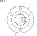
- an oblique diameter dimension D of the second spiral groove 42 (a dimension between grooves facing each other at a phase of 180° in a state where the groove advances by 0.5 lead) is measured using the measurement terminal. Therefore, at least one of the second spiral grooves 42 remains 0.5 leads (indicated by a dimension L in FIG. 2 ) or more.
- the oblique diameter dimension D of a portion of the second spiral groove 42 is the same dimension as an oblique diameter dimension of the first spiral groove 41. That is, since the first spiral groove 41 has a shape obtained by cutting off the intermediate ridge portion 44 between the two second spiral grooves 42, the oblique diameter dimension D between the grooves of the second spiral groove 42 represents the oblique diameter dimension of the first spiral groove 41.
- the ball-shaped fixture or the measurement terminal is stably held by the left and right flanks 42c of the second spiral groove 42, so that the oblique diameter dimension D can be accurately measured.
- the other second spiral groove 42 is formed at an opposite side to the one second spiral groove 42 by 180° at the two same positions in the axial direction. Therefore, it is sufficient that there is a groove short enough to set a measurement instrument and the measurement terminal, and a groove length L1 of the second spiral groove 42 is equal to or larger than a diameter of the ball.
- a quill 50 used for grinding has a pair of grinding stones 51 matching the shape of the flank 41c of the first spiral groove 41, and is set to be inclined along a lead angle ⁇ of the first spiral groove 41 with respect to the central axis CL, and by rotating the grinding stone 51 at a high speed, the flanks 41c of the adjacent first spiral grooves 41 and the flanks 42c of the adjacent second spiral grooves 42, which are on both left and right sides with respect to the ridge portion 43, are machined.
- the second spiral groove 42 for measuring the oblique diameter dimension may be formed in the screw shaft 3.
Landscapes
- Engineering & Computer Science (AREA)
- General Engineering & Computer Science (AREA)
- Mechanical Engineering (AREA)
- Transmission Devices (AREA)
Applications Claiming Priority (2)
| Application Number | Priority Date | Filing Date | Title |
|---|---|---|---|
| JP2021062357 | 2021-03-31 | ||
| PCT/JP2022/013763 WO2022210223A1 (fr) | 2021-03-31 | 2022-03-23 | Vis sphérique à rangées multiples |
Publications (3)
| Publication Number | Publication Date |
|---|---|
| EP4317742A1 true EP4317742A1 (fr) | 2024-02-07 |
| EP4317742A4 EP4317742A4 (fr) | 2024-08-28 |
| EP4317742B1 EP4317742B1 (fr) | 2026-04-08 |
Family
ID=83458723
Family Applications (1)
| Application Number | Title | Priority Date | Filing Date |
|---|---|---|---|
| EP22780437.4A Active EP4317742B1 (fr) | 2021-03-31 | 2022-03-23 | Vis sphérique à rangées multiples |
Country Status (6)
| Country | Link |
|---|---|
| US (1) | US12241527B2 (fr) |
| EP (1) | EP4317742B1 (fr) |
| JP (1) | JP7800538B2 (fr) |
| CN (1) | CN117157475B (fr) |
| TW (1) | TWI885253B (fr) |
| WO (1) | WO2022210223A1 (fr) |
Family Cites Families (12)
| Publication number | Priority date | Publication date | Assignee | Title |
|---|---|---|---|---|
| US1831080A (en) * | 1928-10-22 | 1931-11-10 | Benjamin F Schmidt | Ball bearing screw and nut |
| FR2204272A5 (fr) | 1972-10-20 | 1974-05-17 | Tech Integrale S | |
| JPS56120851A (en) | 1980-02-29 | 1981-09-22 | Hiroshi Teramachi | Ball screw with retainer |
| JPS56147954A (en) * | 1980-04-17 | 1981-11-17 | Hiroshi Teramachi | Retainerless ball screw |
| JPS56147955A (en) | 1980-04-17 | 1981-11-17 | Hiroshi Teramachi | Ball screw with holder |
| JPS61182451U (fr) * | 1985-05-08 | 1986-11-14 | ||
| JPH05118406A (ja) * | 1991-10-23 | 1993-05-14 | Masao Moriyama | ボールねじ |
| CN100398872C (zh) | 2004-08-20 | 2008-07-02 | 上银科技股份有限公司 | 滚动螺杆 |
| US8757024B2 (en) | 2010-03-30 | 2014-06-24 | Linear Motion, Llc | Linear motion assembly with recirculation insert |
| JP2015025544A (ja) * | 2013-07-29 | 2015-02-05 | 株式会社ジェイテクト | ボールねじ装置 |
| WO2018088506A1 (fr) * | 2016-11-14 | 2018-05-17 | 日本精工株式会社 | Vis à billes |
| JP7432888B2 (ja) | 2019-10-11 | 2024-02-19 | 株式会社industria | 微細物除去システム及び微細物除去装置 |
-
2022
- 2022-03-23 US US18/285,049 patent/US12241527B2/en active Active
- 2022-03-23 CN CN202280026372.4A patent/CN117157475B/zh active Active
- 2022-03-23 JP JP2023511096A patent/JP7800538B2/ja active Active
- 2022-03-23 EP EP22780437.4A patent/EP4317742B1/fr active Active
- 2022-03-23 WO PCT/JP2022/013763 patent/WO2022210223A1/fr not_active Ceased
- 2022-03-31 TW TW111112502A patent/TWI885253B/zh active
Also Published As
| Publication number | Publication date |
|---|---|
| CN117157475A (zh) | 2023-12-01 |
| JPWO2022210223A1 (fr) | 2022-10-06 |
| TW202242280A (zh) | 2022-11-01 |
| JP7800538B2 (ja) | 2026-01-16 |
| EP4317742B1 (fr) | 2026-04-08 |
| CN117157475B (zh) | 2026-06-09 |
| US20240191789A1 (en) | 2024-06-13 |
| EP4317742A4 (fr) | 2024-08-28 |
| TWI885253B (zh) | 2025-06-01 |
| WO2022210223A1 (fr) | 2022-10-06 |
| US12241527B2 (en) | 2025-03-04 |
Similar Documents
| Publication | Publication Date | Title |
|---|---|---|
| US20250305567A1 (en) | Ball screw device | |
| JP6962398B2 (ja) | ボールねじ装置 | |
| US20100242651A1 (en) | Rolling-element screw device | |
| KR910004259B1 (ko) | 회전운동을 축운동으로 변환하는 장치 | |
| KR920007779B1 (ko) | 복합 운동 안내 유닛 및 그를 사용한 복합 운동 안내장치 | |
| KR20080064865A (ko) | 볼 나사 장치 | |
| JP2008202672A (ja) | ボールねじ及びその製造方法 | |
| EP4317742B1 (fr) | Vis sphérique à rangées multiples | |
| JP4288903B2 (ja) | ボールねじ装置 | |
| US3908400A (en) | Constant velocity universal joint | |
| TWI670429B (zh) | 滾珠螺桿 | |
| JPH0357346B2 (fr) | ||
| CN101184935B (zh) | 滚珠螺杆、运动导向装置 | |
| RU2085842C1 (ru) | Способ контроля размеров рабочих поверхностей колец двухрядных радиально-упорных шарикоподшипников | |
| JP4095277B2 (ja) | リニアブッシュ及びリニアブッシュ用軌道軸 | |
| TWI910334B (zh) | 多列軸承及軸承單元 | |
| JP2025089774A (ja) | ボールねじ | |
| US20190337062A1 (en) | Method of manufacturing an elbow, cutting tool, and elbow | |
| EP3295058B1 (fr) | Mécanisme d'entraînement linéaire du type à vis et écrou à contact de roulement parfait | |
| KR950011320B1 (ko) | 헤링 본 그루우브드 저널 베어링의 그루우브 가공장치 | |
| EP4317743A1 (fr) | Vis à billes | |
| JP2026065293A (ja) | ボールねじ装置 | |
| JP7472633B2 (ja) | 被加工物の支持装置 | |
| US7530282B2 (en) | Ball screw apparatus | |
| JP5487450B2 (ja) | 軸受装置におけるエンコーダの加工方法 |
Legal Events
| Date | Code | Title | Description |
|---|---|---|---|
| STAA | Information on the status of an ep patent application or granted ep patent |
Free format text: STATUS: THE INTERNATIONAL PUBLICATION HAS BEEN MADE |
|
| PUAI | Public reference made under article 153(3) epc to a published international application that has entered the european phase |
Free format text: ORIGINAL CODE: 0009012 |
|
| STAA | Information on the status of an ep patent application or granted ep patent |
Free format text: STATUS: REQUEST FOR EXAMINATION WAS MADE |
|
| 17P | Request for examination filed |
Effective date: 20230929 |
|
| AK | Designated contracting states |
Kind code of ref document: A1 Designated state(s): AL AT BE BG CH CY CZ DE DK EE ES FI FR GB GR HR HU IE IS IT LI LT LU LV MC MK MT NL NO PL PT RO RS SE SI SK SM TR |
|
| DAV | Request for validation of the european patent (deleted) | ||
| DAX | Request for extension of the european patent (deleted) | ||
| A4 | Supplementary search report drawn up and despatched |
Effective date: 20240730 |
|
| RIC1 | Information provided on ipc code assigned before grant |
Ipc: F16H 25/24 20060101ALI20240725BHEP Ipc: F16H 25/22 20060101AFI20240725BHEP |
|
| GRAP | Despatch of communication of intention to grant a patent |
Free format text: ORIGINAL CODE: EPIDOSNIGR1 |
|
| STAA | Information on the status of an ep patent application or granted ep patent |
Free format text: STATUS: GRANT OF PATENT IS INTENDED |
|
| INTG | Intention to grant announced |
Effective date: 20251105 |
|
| GRAS | Grant fee paid |
Free format text: ORIGINAL CODE: EPIDOSNIGR3 |
|
| GRAA | (expected) grant |
Free format text: ORIGINAL CODE: 0009210 |
|
| STAA | Information on the status of an ep patent application or granted ep patent |
Free format text: STATUS: THE PATENT HAS BEEN GRANTED |
|
| AK | Designated contracting states |
Kind code of ref document: B1 Designated state(s): AL AT BE BG CH CY CZ DE DK EE ES FI FR GB GR HR HU IE IS IT LI LT LU LV MC MK MT NL NO PL PT RO RS SE SI SK SM TR |
|
| REG | Reference to a national code |
Ref country code: CH Ref legal event code: F10 Free format text: ST27 STATUS EVENT CODE: U-0-0-F10-F00 (AS PROVIDED BY THE NATIONAL OFFICE) Effective date: 20260408 Ref country code: GB Ref legal event code: FG4D |
|
| REG | Reference to a national code |
Ref country code: DE Ref legal event code: R096 Ref document number: 602022034158 Country of ref document: DE |
|
| REG | Reference to a national code |
Ref country code: IE Ref legal event code: FG4D |