EP4317766A2 - Ensemble de composants d'éclairage avec système de connexion et dispositif d'éclairage pour le kit - Google Patents
Ensemble de composants d'éclairage avec système de connexion et dispositif d'éclairage pour le kit Download PDFInfo
- Publication number
- EP4317766A2 EP4317766A2 EP23178870.4A EP23178870A EP4317766A2 EP 4317766 A2 EP4317766 A2 EP 4317766A2 EP 23178870 A EP23178870 A EP 23178870A EP 4317766 A2 EP4317766 A2 EP 4317766A2
- Authority
- EP
- European Patent Office
- Prior art keywords
- lighting
- elements
- rows
- lighting elements
- component
- Prior art date
- Legal status (The legal status is an assumption and is not a legal conclusion. Google has not performed a legal analysis and makes no representation as to the accuracy of the status listed.)
- Pending
Links
Images


Classifications
-
- F—MECHANICAL ENGINEERING; LIGHTING; HEATING; WEAPONS; BLASTING
- F21—LIGHTING
- F21S—NON-PORTABLE LIGHTING DEVICES; SYSTEMS THEREOF; VEHICLE LIGHTING DEVICES SPECIALLY ADAPTED FOR VEHICLE EXTERIORS
- F21S2/00—Systems of lighting devices, not provided for in main groups F21S4/00 - F21S10/00 or F21S19/00, e.g. of modular construction
- F21S2/005—Systems of lighting devices, not provided for in main groups F21S4/00 - F21S10/00 or F21S19/00, e.g. of modular construction of modular construction
-
- F—MECHANICAL ENGINEERING; LIGHTING; HEATING; WEAPONS; BLASTING
- F21—LIGHTING
- F21S—NON-PORTABLE LIGHTING DEVICES; SYSTEMS THEREOF; VEHICLE LIGHTING DEVICES SPECIALLY ADAPTED FOR VEHICLE EXTERIORS
- F21S10/00—Lighting devices or systems producing a varying lighting effect
- F21S10/02—Lighting devices or systems producing a varying lighting effect changing colors
- F21S10/023—Lighting devices or systems producing a varying lighting effect changing colors by selectively switching fixed light sources
-
- F—MECHANICAL ENGINEERING; LIGHTING; HEATING; WEAPONS; BLASTING
- F21—LIGHTING
- F21S—NON-PORTABLE LIGHTING DEVICES; SYSTEMS THEREOF; VEHICLE LIGHTING DEVICES SPECIALLY ADAPTED FOR VEHICLE EXTERIORS
- F21S10/00—Lighting devices or systems producing a varying lighting effect
- F21S10/06—Lighting devices or systems producing a varying lighting effect flashing, e.g. with rotating reflector or light source
-
- F—MECHANICAL ENGINEERING; LIGHTING; HEATING; WEAPONS; BLASTING
- F21—LIGHTING
- F21V—FUNCTIONAL FEATURES OR DETAILS OF LIGHTING DEVICES OR SYSTEMS THEREOF; STRUCTURAL COMBINATIONS OF LIGHTING DEVICES WITH OTHER ARTICLES, NOT OTHERWISE PROVIDED FOR
- F21V21/00—Supporting, suspending, or attaching arrangements for lighting devices; Hand grips
- F21V21/005—Supporting, suspending, or attaching arrangements for lighting devices; Hand grips for several lighting devices in an end-to-end arrangement, i.e. light tracks
-
- F—MECHANICAL ENGINEERING; LIGHTING; HEATING; WEAPONS; BLASTING
- F21—LIGHTING
- F21V—FUNCTIONAL FEATURES OR DETAILS OF LIGHTING DEVICES OR SYSTEMS THEREOF; STRUCTURAL COMBINATIONS OF LIGHTING DEVICES WITH OTHER ARTICLES, NOT OTHERWISE PROVIDED FOR
- F21V21/00—Supporting, suspending, or attaching arrangements for lighting devices; Hand grips
- F21V21/08—Devices for easy attachment to any desired place, e.g. clip, clamp, magnet
- F21V21/0832—Hook and loop-type fasteners
-
- F—MECHANICAL ENGINEERING; LIGHTING; HEATING; WEAPONS; BLASTING
- F21—LIGHTING
- F21V—FUNCTIONAL FEATURES OR DETAILS OF LIGHTING DEVICES OR SYSTEMS THEREOF; STRUCTURAL COMBINATIONS OF LIGHTING DEVICES WITH OTHER ARTICLES, NOT OTHERWISE PROVIDED FOR
- F21V21/00—Supporting, suspending, or attaching arrangements for lighting devices; Hand grips
- F21V21/08—Devices for easy attachment to any desired place, e.g. clip, clamp, magnet
- F21V21/096—Magnetic devices
-
- F—MECHANICAL ENGINEERING; LIGHTING; HEATING; WEAPONS; BLASTING
- F21—LIGHTING
- F21V—FUNCTIONAL FEATURES OR DETAILS OF LIGHTING DEVICES OR SYSTEMS THEREOF; STRUCTURAL COMBINATIONS OF LIGHTING DEVICES WITH OTHER ARTICLES, NOT OTHERWISE PROVIDED FOR
- F21V5/00—Refractors for light sources
- F21V5/04—Refractors for light sources of lens shape
- F21V5/048—Refractors for light sources of lens shape the lens being a simple lens adapted to cooperate with a point-like source for emitting mainly in one direction and having an axis coincident with the main light transmission direction, e.g. convergent or divergent lenses, plano-concave or plano-convex lenses
-
- F—MECHANICAL ENGINEERING; LIGHTING; HEATING; WEAPONS; BLASTING
- F21—LIGHTING
- F21W—INDEXING SCHEME ASSOCIATED WITH SUBCLASSES F21K, F21L, F21S and F21V, RELATING TO USES OR APPLICATIONS OF LIGHTING DEVICES OR SYSTEMS
- F21W2131/00—Use or application of lighting devices or systems not provided for in codes F21W2102/00-F21W2121/00
- F21W2131/40—Lighting for industrial, commercial, recreational or military use
- F21W2131/406—Lighting for industrial, commercial, recreational or military use for theatres, stages or film studios
-
- F—MECHANICAL ENGINEERING; LIGHTING; HEATING; WEAPONS; BLASTING
- F21—LIGHTING
- F21Y—INDEXING SCHEME ASSOCIATED WITH SUBCLASSES F21K, F21L, F21S and F21V, RELATING TO THE FORM OR THE KIND OF THE LIGHT SOURCES OR OF THE COLOUR OF THE LIGHT EMITTED
- F21Y2105/00—Planar light sources
- F21Y2105/10—Planar light sources comprising a two-dimensional [2D] array of point-like light-generating elements
- F21Y2105/14—Planar light sources comprising a two-dimensional [2D] array of point-like light-generating elements characterised by the overall shape of the two-dimensional [2D] array
- F21Y2105/16—Planar light sources comprising a two-dimensional [2D] array of point-like light-generating elements characterised by the overall shape of the two-dimensional [2D] array square or rectangular, e.g. for light panels
-
- F—MECHANICAL ENGINEERING; LIGHTING; HEATING; WEAPONS; BLASTING
- F21—LIGHTING
- F21Y—INDEXING SCHEME ASSOCIATED WITH SUBCLASSES F21K, F21L, F21S and F21V, RELATING TO THE FORM OR THE KIND OF THE LIGHT SOURCES OR OF THE COLOUR OF THE LIGHT EMITTED
- F21Y2113/00—Combination of light sources
- F21Y2113/10—Combination of light sources of different colours
-
- F—MECHANICAL ENGINEERING; LIGHTING; HEATING; WEAPONS; BLASTING
- F21—LIGHTING
- F21Y—INDEXING SCHEME ASSOCIATED WITH SUBCLASSES F21K, F21L, F21S and F21V, RELATING TO THE FORM OR THE KIND OF THE LIGHT SOURCES OR OF THE COLOUR OF THE LIGHT EMITTED
- F21Y2115/00—Light-generating elements of semiconductor light sources
- F21Y2115/10—Light-emitting diodes [LED]
Definitions
- the invention relates to a set of lighting components with a connection system for lighting components, such as those used in particular in event lighting technology, which can be grouped into a cluster by the connection system.
- the invention further relates to a lighting device suitable for this purpose, which can achieve stroboscope-like lighting effects.
- lighting components are arranged at suitable locations in the room and controlled as required.
- the lighting components used include blinders, strobe lights, panel lights and the like, also in a variety of combinations.
- the room can be illuminated in the desired colors and brightness, also varying over time, and on the other hand, targeted, for example short-term, lighting effects can be set.
- targeted blinding effects can be set using one or more blind people and/or bright and fast flashes can be generated using strobe lights, thereby drawing the audience's attention to a particular scene or a sub-area of the room through the lighting effects etc. can be controlled.
- the lighting components themselves can have a suitable design depending on requirements, e.g. be equipped with LEDs in matrix form or row form, use halogen lamps, be constructed in PAR design, etc.
- stroboscopes with a central flash tube are often used for this purpose.
- a stroboscope emits flashes of light at specific, often regular, intervals. The flash duration is less than 5ms, the frequency of the flashes is between 0.5 and 100 Hertz, for example.
- Such strobe-like lighting devices which are traditionally created using xenon flash lamps, are also imitated by using LEDs (light-emitting diodes) in which the LEDs emit white light.
- stroboscope lighting devices with colored lighting means.
- An example of a lighting device that can be varied in a light spectrum at the same time and can therefore be used for colored stage lighting and can be used as a stroboscope is in the DE 2020 170 050 50 U1 described.
- the lighting device described there cannot be used flexibly, in particular for creating larger-area lighting patterns or images.
- the various lighting components are usually installed separately from one another in the room, for example on suitable fastenings, whereby they generally require one fastening per lighting component.
- suitable fastenings for example on suitable fastenings
- the lighting components are used for mobile applications, it is an advantage if they can be flexibly grouped and separated again depending on the desired purpose.
- connection system that enables the flexible and simple grouping of lighting components into a unit. Furthermore, the connection system should be such that the groupings can be converted as required without much effort.
- a further object of the invention is to provide a lighting device which is suitable for providing large-area lighting patterns or images through combination with other lighting devices and can also be used for stroboscope effects as required.
- the invention is based on the idea of providing a part of a connecting mechanism on each lighting component itself of the set of lighting components, so that the lighting components of the set can be connected to one another directly, without the interposition of a holder or the like.
- This allows an arrangement of lighting components (clusters) to be created that have a uniform overall appearance.
- the lighting components are preferably coordinated in shape, for example in that all the lighting components are cuboid or cube-shaped and their side surfaces, on which they can be connected to one another, i.e. which form the connecting surfaces to an adjacent lighting component, are each an integer multiple of one another in their dimensions, in particular the length and/or width.
- a set of lighting components contains a first lighting component with a first connection surface of the first lighting component and a second lighting component with a first connection surface of the second lighting component.
- a first connecting element of a connecting mechanism is provided on the first connecting surface of the first lighting component and a second connecting element of a connecting mechanism is provided on the first connecting surface of the second lighting component.
- the second connecting element of a connecting mechanism is complementary to the first connecting element of the connecting mechanism, so that the first lighting component can be releasably connected to the second lighting component by releasably connecting the first connecting element to the second connecting element.
- the lighting components to be connected to one another can be pre-positioned and pre-connected to one another.
- Such pre-positioning and pre-connection not only enables the lighting components to be aligned with one another in their assembly position and thus fastening can be carried out more easily, for example even in unfavorable positions or locations, but also that the pre-connection can be made with a suitable choice of pre-connection, for example by means of a sufficiently strong one Magnets ensure that the lighting components hold their position during assembly, for example against gravity when installed overhead.
- the first lighting component and the second lighting component each additionally have an element of a guiding and positioning mechanism on their connecting surface for pre-positioning and pre-connecting the first and second lighting components.
- the element of the guiding and positioning mechanism of the first lighting component can be a first magnetic element (south pole) and the element of the guiding and positioning mechanism of the second lighting component can be a second magnetic element (north pole) attracted thereto.
- a pre-attachment can be carried out using the guiding and positioning mechanism, e.g. if sufficiently strong magnetic elements are selected, before the lighting components are locked together using the connecting mechanism.
- the pre-connection is so reliable and strong that the lighting components hold together, at least temporarily, without further fastening during assembly and disassembly.
- the number of lighting components in a set is not limited to two. Rather, the set can have any number of lighting components of the same or different types.
- first and second connecting elements are each provided on a connecting surface also includes arrangements in which the connecting elements are not attached directly to the surface itself, which can be formed, for example, by a non-supporting housing cover. Rather, this includes arrangements in which the connecting elements are attached to the lighting component itself in the immediate vicinity of these connecting surfaces.
- one of the connecting elements can be set back into the interior of the housing of the lighting component relative to a connecting surface formed by a housing cover and the other of the connecting elements can protrude relative to the connecting surface or at least be brought into a projecting position.
- Complementary connecting elements between the first and second connecting elements include all connecting solutions, e.g. non-positive and/or positive, in which a first element of a connecting mechanism can be brought into engagement with a second element of a connecting mechanism to connect the two elements to one another.
- the first connecting surface of the first lighting component and the first connecting surface of the second lighting component are shaped in a complementary manner.
- the connecting surfaces can both be shaped as a plane, in particular the side surface of a cuboid, or one of the connecting surfaces is concave and the other is correspondingly convexly curved. This enables a uniform, harmonious image when arranging several lighting components as a group or cluster.
- a plurality of connecting surfaces are provided on one or more lighting components of the set, with the different connecting surfaces preferably having partly the first element of the connecting mechanism and partly the second element of the connecting mechanism.
- the first lighting component has, in addition to the first connection surface with the first element of the connection mechanism, a second connection surface on which a second element of a connection mechanism is provided.
- the second connecting surface of the first lighting component lies opposite the first connecting surface of the first lighting component, in particular if the lighting component itself is shaped as a cuboid. If opposite surfaces, i.e. opposite side surfaces of the cuboid, are then used as connecting surfaces with the corresponding connecting elements, a group with a uniform appearance can be created through any combination and arrangement of different lighting components, which can be set up together as a group or attached to a suspension.
- the second lighting component in particular further has a second connection surface on which a first element of a connection mechanism is provided.
- the second connecting surface of the second lighting component lies opposite the first connecting surface of the second lighting component.
- both a first element of a connection mechanism and a second element of a connection mechanism are provided on the first connection surface and/or on the second connection surface. This means that the connecting surface with the corresponding connecting element can be used flexibly as required by selecting the first or second connecting element as required.
- first lighting component and the second lighting component are cuboid and a first connecting element and/or a second connecting element is provided on all four side surfaces of at least one of the first or second lighting components. This also creates very flexible options in terms of possible combinations for arranging multiple lighting components.
- one of the first or second connecting elements is provided as an element protruding from the connecting surface with a shape that can form a positive connection with the shape of the other of the first or second connecting elements, this connecting element is set back from the connecting surface.
- this connecting element may be housed inside a housing and accessible through an opening in the connecting surface, so that the protruding connecting element, when placed in a position protruding from the connecting surface, can be engaged with the second connecting element inside the housing can.
- the first connecting element is provided as a hook element and the second connecting element as a bolt element or vice versa.
- the hook element can be brought into the position protruding from the connecting surface by a rotating mechanism, i.e. the user operates a handle element for rotation and thus rotates the connecting element out of the housing of the lighting element into the position protruding from the connecting surface in which it is can lock or engage with the other connecting element on the other lighting component if, for example, it is set back relative to the housing of the other lighting component.
- a rotating mechanism i.e. the user operates a handle element for rotation and thus rotates the connecting element out of the housing of the lighting element into the position protruding from the connecting surface in which it is can lock or engage with the other connecting element on the other lighting component if, for example, it is set back relative to the housing of the other lighting component.
- the first and/or the second lighting component of the set or the multiple lighting components of the set could each be a blind, a spotlight, a spotlight, a strobe, a surface light, a surface spotlight or a connectable loudspeaker.
- Several identical lighting components or different lighting components can form a set as required.
- the lighting component is a lighting device that can be used simultaneously as stroboscope lighting and as area lighting, in particular in combination with several similar lighting devices of this type.
- a lighting device includes a plurality of first lighting elements that are designed to emit light in a fixed first light spectrum, and a plurality of second lighting elements that are designed to emit light in a variable light spectrum, the first lighting elements and the second Lighting elements are each arranged in at least two rows of first lighting elements and at least two rows of second lighting elements, with at least part of the rows of first lighting elements being arranged as a single row.
- This provides a lighting device which, on the one hand, can be used for stroboscope effects for stage lighting, for example, and, on the other hand, can also be used for colored lighting effects, the lighting device being designed in such a way both for stroboscope effects and for the provision of colored lighting. that different lighting patterns can be created both within the framework of the individual lighting device and by combining several lighting devices into a set.
- the lighting device is characterized in that those lighting elements that generate stroboscope effects are not only provided as a strip in a central area of the lighting device, as in a classic stroboscope, but rather are arranged in a special distribution on the surface of the lighting device .
- the lighting elements are generally arranged in rows on a substantially two-dimensional surface at regular intervals from one another at least in one direction of the surface. I.e. both the first and the second lighting elements are each arranged in rows of first lighting elements or rows of second lighting elements. In the direction perpendicular to these rows, the lighting elements can also be arranged at the same distances from one another as the lighting elements of a single row, or larger distances can be provided between adjacent rows. Either first lighting elements or second lighting elements are provided within a row and the lighting elements are not mixed. Through this arrangement of the first and second lighting elements, in addition to at least two line or strip-shaped stroboscopic lighting effects, colored lighting can also be generated by means of the second lighting elements, to which no fixed light spectrum is assigned.
- first lighting elements are arranged in a single row of first lighting elements means that the arrangement is interrupted in the direction perpendicular to the direction of the row by rows of second lighting elements and/or that two rows
- the first lighting elements are spaced so far apart that when illuminated the row appears as a single line and does not merge with an adjacent row. For example, the distance between two rows is chosen to be greater than the distance between two lighting elements in a row, or one row is left out.
- a block of several rows of first lighting elements can also be formed in order to achieve the effect of a wider light strip.
- the first and second lighting elements can all be arranged on a common panel or multiple panels can be provided, each carrying first lighting elements or second lighting elements or combinations of first and second lighting elements.
- the fixed first light spectrum of the first lighting elements is white, preferably cold white. This serves to achieve a strobe effect using the first lighting elements. If several rows of first lighting elements with a white light spectrum are provided immediately adjacent to one another in an area of the lighting device, these achieve a strip-shaped or tubular effect when they are controlled together for lighting, which can be perceived as a stroboscope effect when the The activation duration is short enough, for example below 5 ms, so that the lighting up in white or cold white is perceived as a white flash.
- white lighting elements the energy density required for stroboscope effects can be achieved (in contrast to lighting elements with variable spectrum, which can also produce white light, among other things).
- variable light spectrum of the second lighting elements is an RGB light spectrum. More preferably, the lighting elements can be varied in the emitted color, ie the emitted light, depending on their control, and a wide variety of lighting effects can thus be achieved.
- the first and second lighting elements are each LEDs. This means that all lighting elements can be arranged on a common panel if desired.
- the use of LEDs makes sense from a thermal perspective and with regard to energy consumption, as they emit little heat and consume relatively little electricity with relatively high light energy.
- the rows of first lighting elements which are arranged as a single row, are each covered with an elliptical lens. This imitates the appearance of the lighting of conventional, traditional xenon bulbs.
- At least three rows of first lighting elements are provided, and some of the rows of first lighting elements are grouped into a group of first lighting elements with at least two immediately adjacent rows of first lighting elements. If, for example, three rows of first lighting elements are provided, then in addition to the one row of first lighting elements, which is arranged as a single row, a group of two rows of first lighting elements is provided.
- Such grouped rows of first lighting elements can particularly preferably be provided as a unit that can be controlled together, for example by being arranged on a single, common support.
- first lighting elements Preferably, several individual rows of first lighting elements are provided.
- these individual rows are arranged symmetrically to an axis of symmetry of the lighting device running in the direction of the rows, are at the same distance from one another and, in particular, the outermost of the individual rows are each half of this distance from the edge of the lighting device, combinations of several lighting devices and controls can be used
- Rows of first lighting elements or partial areas of these rows display a variety of patterns, symbols, graphics, etc.
- this group of rows of first lighting elements or one of the groups of rows of first lighting elements is in a central area of the lighting device, arranged in the direction perpendicular to the rows.
- this group is provided centrally on the lighting device, then by combining several lighting devices next to each other in the direction of the rows, a continuous stroboscope line can be imitated over several lighting devices, which also merge into an overall structure.
- the central position of the group can, for example, produce a uniform stripe pattern on each of the lighting devices.
- a central group of five rows of first lighting elements is provided. These rows of the central group of first lighting elements can particularly preferably be provided on a single, common LED carrier and can be controlled together. Such a grouping of several rows of first lighting elements has the advantage and the effect that a relatively high output power can be achieved in a very compact area. This allows high luminosity and brightness to be achieved. Adjacent to this group in the direction perpendicular to the rows, a single row of first lighting elements, a group of five rows of second lighting elements and a further single row of first lighting elements are provided on both sides, axially symmetrical to an axis of symmetry running along the central row. This means that a variety of patterns, graphics, etc. can be created both with a single lighting device and when combining several lighting devices.
- rows of first lighting elements are arranged as a group, they are preferably covered with a common elliptical lens, so that the effect of a xenon tube is achieved and imitated.
- the lighting elements of the group of first lighting elements and/or the lighting elements of the individual rows of first lighting elements are grouped in the direction along the longitudinal direction of the rows into a plurality of segments that can be controlled separately from one another. It is particularly preferred if at least the individual rows of first lighting elements can be controlled separately from one another in several rows Segments, for example 12 segments, are provided. For example, 6 or 12 separately controllable segments can be provided along a row. This further increases flexibility and the ability to display a variety of patterns, shapes and graphics.
- At least some of the rows of second lighting elements are grouped into a group of second lighting elements with at least two immediately adjacent rows of second lighting elements. This allows different color patterns to be achieved.
- the lighting elements of the group of second lighting elements are grouped in the direction along the longitudinal direction of the rows into several segments that can be controlled separately from one another. For example, 6 or 12 separately controllable segments can be provided along a row. This further increases flexibility and the ability to display a variety of patterns, shapes and graphics.
- the lighting device preferably further contains a control device for controlling the lighting elements or the groups or segments of lighting elements.
- Figures 1 to 7 each show different embodiments of a set 100 of lighting components according to the present invention, wherein the lighting components 10, 11, 12, 20, 21, 22 are each shown in the assembled state.
- Figure 1 shows a set 100 consisting of a first blinder 10 and a second blinder 11, each of which is designed as a so-called two-group blinder, ie each has 2 groups of light sources, for example LEDs.
- Each of the blinds 10, 11 is designed essentially cuboid, that is, in the top view of the light-emitting side, each of the blinds 10, 11 has a substantially rectangular base area.
- the width of each blinder is 10, 11 (left-right direction in Figure 1 ) twice as large as their height (high-low direction in Figure 1 ).
- each blinder 10, 11 has the two light source groups, which are next to each other, ie horizontally Figure 1 , are arranged.
- the first blinder 10 and the second blinder 11, which form a first lighting component and a second lighting component, respectively, are shown in FIG Figure 1 illustrated embodiment arranged vertically one above the other, being stacked and connected to one another on the longer side surface of their cuboid housing. Furthermore, a common bracket 15, which serves as a handle, assembly or holding bracket, is provided on one of the blinds 10.
- the set consists of 100 lighting components Figures 2 and 3 differs from that in Figure 1 shown in it that three blinders 10, 11, 12, each of which is designed identically and the in Figure 1 blinders 10, 11 shown correspond to each other and are arranged into a cluster by being stacked on one another along their respective longitudinal side surfaces of their cuboid housings and connected to one another via a connecting mechanism which is in connection with Figures 8 to 16 is described in more detail.
- the set 100 also has a mounting or holding bracket 15, which is in Figure 2 when assembled, in Figure 3 shown in the detached state from the set.
- Two blinders 10, 11 are provided, which correspond to the blinders 10, 11 Figures 1 to 3 are equivalent to.
- a surface spotlight 20 that can be coupled to the blinders 10, 11 or the light effects generated by them is arranged as a further, third lighting component.
- the surface radiator 20, which therefore has the same Light and possibly sound system such as the blinders 10, 11 can be coupled is also cuboid, although its dimensions are in the height direction (essentially in the high-low direction in Figure 4 ) is only half that of the blinds 10, 11 (or the height of the blinds 10, 11 is twice that of the surface radiator 20).
- the width (left-right direction in Figure 4 ) and the depth of the blinds 10, 11 and the surface radiator 21 are each the same.
- FIG. 4 In the set shown and its arrangement, various lighting components are stacked and attached to each other using a connecting mechanism (described in more detail later).
- a mounting or holding bracket 15 is attached to one of the blinds 10.
- the bracket 15 can also serve as a handle bracket.
- Figure 5 shows a set 100 of lighting components, with two surface spotlights 20, 21 and a blinder 10 being provided.
- the surface radiators 20, 21 and the blinder 10 correspond in shape and dimensions to those of the previously described embodiments.
- the blinder 10 is oriented vertically, that is, its longitudinal direction runs in the state of use, which is shown in Figure 5 is shown in the high-low direction.
- a surface radiator 20, 21 is connected via the long side surfaces of the cuboids that form the connecting surfaces.
- a mounting or holding bracket 15 is provided with one bracket end on one of the surface radiators 20, 21 and is attached to the arrangement.
- the embodiment shown consists of two blinders 10, 11 of the same design as that of the previously described embodiments, with one of the blinders 10 having a bracket (as a handle bracket, mounting bracket and / or holding bracket) 15 attached.
- a bracket as a handle bracket, mounting bracket and / or holding bracket
- the blinders 10, 11 in this case are combined with one another along their short side surfaces as connecting surfaces. This is made possible by the fact that in the blinders 10, 11 a connecting mechanism 50, which is described in more detail below, is provided as lighting components on each of the side surfaces of the cuboid.
- Figure 7 finally shows an arrangement of a blinder 10 (same design as that of the previously described embodiments) and three surface radiators 20, 21, 22.
- the surface radiators 20, 21 correspond to the surface radiators 20, 21, which are used in connection with the in Figure 5 shown embodiment are described, the surface radiator 22 corresponds in terms of its size, the dimensions of the blinder 10, ie it is twice as long in its height direction as the surface radiators 20, 21.
- the surface radiators 22 are on one side and the surface radiators 20, 21 on the other side, each with their small side surfaces arranged as connecting surfaces and tied together.
- a carriage is also attached to the blinder, which can be used, for example, to guide the set 100 in a rail attached to a ceiling of a room.
- connection mechanism 50 is described using the example of a set 100 of lighting components from two blinders 10, 11.
- the blinder 10 corresponds to the first lighting component and the blinder 11 to the second lighting component.
- Figure 8 shows the blinds 10, 11 in a separated state in a perspective view from the back, ie from the side opposite the light outlet.
- the Blinders 10, 11 are both constructed identically and are essentially cuboid in shape. Essentially cuboid includes shapes like those here Figure 8 shown, in which, for example, a projecting housing part is provided on the back, behind which electronic components, control components, etc. can be provided.
- the blinds 10, 11 each have four essentially rectangular side surfaces 40, 41 and 42, 43, respectively, the side surfaces 40, 42 being the side surfaces located along the longitudinal extent of the cuboid and the side surfaces 41, 43 being the side surfaces perpendicular thereto, ie the relatively short side surfaces.
- Each cuboid has two side surfaces of the same dimensions.
- the left-right direction is used for descriptive purposes Figure 8 as the length of the cuboid and the direction up-down in Figure 8 referred to as the height of the cuboid.
- the length of the cuboid of the blinds 10, 11 is twice (twice) the height of the cuboids of the blinds 10, 11.
- a fastening bushing 70 is provided centrally, in the center of gravity, on which additional elements, such as a bracket 15 (shown in Figures 1 to 6 ), which serves as a handlebar, as a mounting bracket and/or as a holding bracket, can be attached.
- the fastening bushing 70 is designed such that a bracket 15 or a similar transport or attachment component for attaching the set 100 to an external holder can be locked by means of, for example, a bayonet lock.
- the fastening bushing 70 is preferably provided with four positions, each offset by 90 degrees to one another, in which connection points of a bracket 15 can be inserted into the fastening bushing 70 and then the bracket 15 can be locked in the fastening bushing 70, for example by rotating it through 45 degrees, ie it Four mounting positions offset by 90 degrees to each other are possible.
- a bracket 15, for example a handle bracket, a mounting bracket or a holding bracket, or a corresponding transport or attachment component can be attached flexibly and as required depending on the orientation of the blinds 10, 11.
- a bracket 15 or similar could also be attached to the lighting component set 100 by means of the connecting mechanism 50, as shown in FIG Figure 7 in connection with the carriage 16 is shown.
- each blinder 10, 11 are constructed identically with regard to the provision of the fastening bushing 70 and the connecting mechanism 50.
- fastening bushings 70 and/or connecting mechanisms 50 could also be provided on only part of the side surfaces of the blinds 10, 11, for example only on one side surface each.
- connection mechanism 50 between the blinders 10, 11 is described below using the connection mechanism 50 attached to the side surfaces 40, 42.
- Each blind 10, 11 has a housing 30, 31 to cover it.
- the housing 30, 31 has been omitted to illustrate the connecting mechanism 50.
- openings 33 or recesses are provided in the housing, which enable the first connecting elements 52 of the connecting mechanism 50 to pass through them and to be connected to the second connecting elements 54 of the blinder 10 Connecting mechanism 50 to engage.
- two openings 33 are provided on the side surface 40 in a central position in the depth direction of the side surface 40 and axially symmetrical to a central axis in the longitudinal direction.
- bolts 54 are arranged as second connecting elements.
- corresponding openings 33 are provided at identical positions in the housing 31 on the side surface 42 of the blinder 11, which corresponds to the first connecting surface of the second lighting component.
- the hook elements 52 attached to the blinder 11 as the first connecting elements can be unscrewed through these openings 33 by means of a corresponding rotating mechanism or, when not in use, screwed back into the housing 31.
- the side surfaces 40, 42 of the blinds additionally have guide or positioning elements which serve to bring two lighting components into alignment with one another more easily and more stably.
- the guide and positioning elements are designed by elongated, rail-like guide projections 35 and corresponding guide grooves 34, so that a blinder 10 can be pushed onto the other blinder 11 in the longitudinal direction of the blinder 10.
- flat, strong magnets are provided in the guide grooves 34, which form a magnetic connection with corresponding reversely polarized magnets in the area of the guide projections.
- the magnets can also be used as guiding and positioning elements without positive guiding and positioning elements, that is, in the case shown, the grooves and projections, or alternatively, only positive elements can be used as guiding and positioning elements, without the magnets.
- Magnets have the advantage that, for example, additional elements can be pre-assembled from below using the attractive force of the magnets before a lock is operated.
- the guiding and positioning elements can be designed exclusively as magnets or in other shapes.
- guide and positioning elements can be provided on both connecting surfaces 40, 42, for example as guide grooves and guide projections, or alternatively, a guide projection can be provided on one connecting surface and only one guide groove on the other, i.e. each connecting surface 40, 42 has only one of the complementary guiding and positioning elements, e.g. in the case of magnets only a north or a south pole magnet
- rotary handles 60 are provided for moving the hook elements 52.
- a rotary handle is provided for each connecting surface and associated connecting element (hook element 52) or possibly also for several hook elements on the same connecting surface.
- the upper rotary handle 60 shown is used to actuate a hook element on the side surface 41 of the blinder 10 perpendicular to the connecting surface 42.
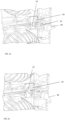
- the mode of operation is corresponding and will based on Figures 11 to 15 with the housings 30, 31 removed.
- Figures 10 and 16 show the start and end positions of the rotary handle 60 with the housing 30, 31 attached.
- a locking mechanism can additionally be integrated (not shown), which, for example, presses the rotary handle into a locked position by means of a spring action, so that the rotary handle 60 only acts against the preloading effect of such when pushed or pulled Spring can be actuated and is otherwise locked, for example by a positive fit.
- any extension can be continued Arrangements (clusters) of lighting components can be created that only require a common fastening or holder in the room.
- the set of lighting components (100) is constructed from two or more lighting devices 210, as described below in connection with Figure 17 to Figure 22 to be discribed:
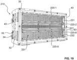
- Figures 17 and 18 show in front view and Figure 19 in a perspective view an embodiment of a lighting device 210, which can be designed as described above with regard to the connection mechanism to adjacent lighting devices 210, but in principle can also be used alone, outside of the set 100.
- a plurality of lighting elements 220, 230 are arranged on a substantially rectangular surface 251 of the lighting device 210
- the lighting elements 220, 230 are designed as LEDs (light-emitting diodes) and can all be arranged on a single, common circuit board, or on several separate circuit boards (not shown).
- the lighting elements 220, 230 of the lighting device 210 are arranged in rows 220-1 to 220-9 or 230-1 to 230-10, which run parallel to the longitudinal edge of the lighting device 210.
- nine rows 220-1 to 220-9 of first lighting elements 220 are provided and ten rows 230-1 to 230-10 of second lighting elements 230 are provided.
- Each row consists, for example, of 68 lighting elements 220, 230 designed as LEDs, with the first lighting elements 220 being designed as CW (cold white) LEDs and the second lighting elements 230 being designed as RGB LEDs.
- the rows 220-1 to 220-9 and 230-1 to 230-10 are arranged symmetrically on the corresponding surface 251 in the direction perpendicular to the direction of a row.
- the row 220-5 of first lighting elements 220 in the illustrated embodiment corresponds to the axis of symmetry of the arrangement.
- first lighting elements 220 Of the nine rows of first lighting elements 220, five rows 220-3, 220-4, 220-5, 220-6 and 220-7 of first lighting elements are arranged centrally in the direction perpendicular to the rows 220-1 to 220-9 and immediately directly next to each other, ie with a distance between two adjacent rows 220-3 to 220-7, which essentially corresponds to the distance between two adjacent lighting elements 220 in a row.
- These rows 220-3 to 220-7 form a group 221 of first lighting elements 220.
- this group 221 of first lighting elements 20 is designed on a common support and can only be controlled together. Ie this group 221 of first lighting elements 220 is designed as a unit and not as individual rows controllable. Alternatively, several, for example five, controllable rows of first lighting elements, in principle separately from one another, but also together, could be arranged as a group and closely spaced.
- rows 220-1, 220-2, 220-8, 220-9 of first lighting elements 220 are arranged as individual rows, i.e. on both sides their distance from an adjacent row of first lighting elements 220 is significantly greater than the distance between two lighting elements 220 in a row to each other and/or they border rows of second lighting elements 230 and/or they are positioned at the edge of the overall arrangement.
- rows 220-1 and 220-9 are positioned at the edge and border rows 230-1 and 230-10 of second lighting elements on their other side.
- the rows 220-2 and 220-8 of first lighting elements border rows 230-5 and 230-6 of second lighting elements on one side and are clearly spaced from rows 220-3 and 220-7 of first lighting elements on the other side.
- the second lighting elements 230 are arranged in two groups 231, 232 of second lighting elements, each with five rows 230-1 to 230-5 and 230-6 to 30-210, i.e. that adjacent rows of second lighting elements are at the same distance from one another as lighting elements 230 of the row to each other.
- the rows 220-1 to 220-9 and 230-1 to 230-10 of the lighting elements 220, 230 are arranged as follows: a single row 220-1 of first lighting elements, a group 231 of five rows 230- 1 to 230-5 second lighting elements, a single row 220-2 of first lighting elements, the central group 221 of first lighting elements, which comprises five rows 220-3 to 220-7 of first lighting elements 220 that can only be controlled together, a single row 220-8 of first lighting elements , a group 232 of five rows 230-6 to 230-10 of second lighting elements, and a single row 220-9 of first lighting elements.
- the distance between the individual rows 220-1 and 220-2 of first lighting elements, the distance between the individual rows 220-2 and 220-8 of first lighting elements, and the distance between the individual rows 220-8 and 220-9 of first lighting elements are chosen identically .
- the distance between the rows 220-1 and 220-9 of first lighting elements to the edge of the lighting device 210 is in each case half as large as the distance, for example, between the individual rows 220-2 and 220-8 of first lighting elements.
- the individual rows 220-1, 220-2, 220-8, 2220-9 of first lighting elements and the central group 221 of the rows 220-3 to 220-7 of first lighting elements are each covered with an elliptical lens 240, 245 to imitate the traditional appearance of xenon tubes.
- the groups 231, 232 of second lighting elements are each divided into six segments 231-1 to 231-6 and 232-1 to 232-6, which can be individually controlled by a controller (not shown). Accordingly (not shown), the individual rows 220-1, 220-2, 220-8 and 220-9 of first lighting elements are each divided into twelve segments along their longitudinal direction, whereby each segment can also be controlled individually.
- the central group 221 of first lighting elements 220 with rows 220-3 to 220-7 is not divided into individual segments. This central group can only be controlled together along its longitudinal direction and at the same time only as a common block, ie across all five rows.
- Figures 20 to 22 each show lighting configurations that can be realized with a set 100 of two lighting devices 210 of the type described, which are connected to one another.
- Figure 20 a configuration is shown in which by controlling and illuminating individual segments of the rows 220-1, 220-2, 220-8 and 220-9 of the two lighting devices 210, ie segments of the four individual rows 220-1, 220-2 , 220-8 and 220-9 first lighting elements, a total of the number "2" is modeled.
- Figure 21 a configuration is shown in which all segments of the rows 220-1, 220-2, 220-8 and 220-9 of the two lighting devices 210, ie all segments of the four individual rows 220-1, 220- 2, 220-8 and 220-9 first lighting elements, a total of a continuous line pattern is realized even across several lighting devices 210.
- Corresponding patterns can also be achieved using the rows of second lighting elements 230-1 to 230-10.
- strobe-like effects can be achieved on the one hand and white and colored lighting patterns can also be created.
- white and colored lighting patterns can also be created.
- continuous effects can be displayed across multiple devices. In this way, the devices merge into one large whole in both horizontal and vertical orientation.
Landscapes
- Engineering & Computer Science (AREA)
- General Engineering & Computer Science (AREA)
- Non-Portable Lighting Devices Or Systems Thereof (AREA)
- Fastening Of Light Sources Or Lamp Holders (AREA)
Applications Claiming Priority (2)
| Application Number | Priority Date | Filing Date | Title |
|---|---|---|---|
| DE102022117390.9A DE102022117390A1 (de) | 2022-07-12 | 2022-07-12 | Set aus Beleuchtungskomponenten mit Verbindungssystem |
| DE102023103124.4A DE102023103124A1 (de) | 2023-02-09 | 2023-02-09 | Beleuchtungsvorrichtung und Set aus Beleuchtungsvorrichtungen |
Publications (2)
| Publication Number | Publication Date |
|---|---|
| EP4317766A2 true EP4317766A2 (fr) | 2024-02-07 |
| EP4317766A3 EP4317766A3 (fr) | 2024-04-10 |
Family
ID=86764623
Family Applications (1)
| Application Number | Title | Priority Date | Filing Date |
|---|---|---|---|
| EP23178870.4A Pending EP4317766A3 (fr) | 2022-07-12 | 2023-06-13 | Ensemble de composants d'éclairage avec système de connexion et dispositif d'éclairage pour le kit |
Country Status (2)
| Country | Link |
|---|---|
| US (2) | US12092277B2 (fr) |
| EP (1) | EP4317766A3 (fr) |
Citations (2)
| Publication number | Priority date | Publication date | Assignee | Title |
|---|---|---|---|---|
| DE102012202148A1 (de) * | 2012-02-13 | 2013-08-14 | Trilux Gmbh & Co. Kg | Lichtbandsystem |
| DE202017005050U1 (de) | 2017-09-29 | 2017-11-16 | Glp German Light Products Gmbh | Beleuchtungsvorrichtung |
Family Cites Families (20)
| Publication number | Priority date | Publication date | Assignee | Title |
|---|---|---|---|---|
| US6314669B1 (en) * | 1999-02-09 | 2001-11-13 | Daktronics, Inc. | Sectional display system |
| DE10139336B4 (de) * | 2001-08-10 | 2012-04-26 | Hartmut S. Engel | Modulares Leuchtensystem |
| DE102007044566A1 (de) * | 2007-09-07 | 2009-03-12 | Arnold & Richter Cine Technik Gmbh & Co. Betriebs Kg | Beleuchtungssystem |
| US9400212B2 (en) * | 2008-06-13 | 2016-07-26 | Barco Inc. | Smart pixel addressing |
| US20120002414A1 (en) * | 2010-06-30 | 2012-01-05 | Carl Gould | Lens for led luminaries |
| US10197224B1 (en) | 2012-05-17 | 2019-02-05 | Colt International Clothing Inc. | Multicolored tube light with improved LED array |
| AU2013280215B2 (en) * | 2012-06-28 | 2017-03-30 | Daktronics, Inc. | Display module mounting |
| WO2014004788A1 (fr) * | 2012-06-28 | 2014-01-03 | Hemiller Ryan | Montage de module d'affichage |
| TWM463620U (zh) * | 2013-05-30 | 2013-10-21 | Everising Machine Company | 具有可適應工件尺寸改變位置的快降桿之帶鋸機 |
| US10889987B2 (en) * | 2017-05-19 | 2021-01-12 | 3Form, Llc | Felt baffle with snap ends |
| FI126862B (fi) * | 2014-08-29 | 2017-06-30 | Absolute Module Oy | Modulaarinen kalustejärjestely ja sen mukainen menetelmä |
| US9995456B2 (en) | 2015-04-14 | 2018-06-12 | Martin Professional Aps | LED strobe light with visual effects |
| WO2017044449A1 (fr) * | 2015-09-09 | 2017-03-16 | Hubbell Incorporated | Ensemble de jonction actionné de l'extérieur destiné à raccorder des structures adjacentes |
| FI126861B (fi) * | 2016-02-29 | 2017-06-30 | Absolute Module Oy | Modulaarinen kalustejärjestely käsittäen toisiinsa sähköisesti ja mekaanisesti liitettäviä moduulikalusteosia |
| US10393329B2 (en) * | 2016-11-17 | 2019-08-27 | Current Lighting Solutions, Llc | Light fixture mechanical interconnect with rotative joining |
| CN209856956U (zh) | 2019-05-07 | 2019-12-27 | 广西思坦科技有限公司 | 一种拼接式触摸壁灯 |
| KR200493471Y1 (ko) | 2019-05-07 | 2021-04-12 | (주)케이아이오티 | 학습 효율을 향상시키는 스마트 조명 장치 |
| CN110985904A (zh) * | 2020-01-02 | 2020-04-10 | 东莞市泰亮半导体照明有限公司 | 一种模组式灯具 |
| CN216591171U (zh) * | 2021-10-28 | 2022-05-24 | 广州达森灯光股份有限公司 | 可拼接的方形灯具 |
| CN216844220U (zh) * | 2021-11-18 | 2022-06-28 | 深圳市华创伟光电有限公司 | 一种拼装式发光二极管灯具 |
-
2023
- 2023-06-13 EP EP23178870.4A patent/EP4317766A3/fr active Pending
- 2023-07-07 US US18/219,207 patent/US12092277B2/en active Active
-
2024
- 2024-04-19 US US18/640,464 patent/US20240280229A1/en not_active Abandoned
Patent Citations (2)
| Publication number | Priority date | Publication date | Assignee | Title |
|---|---|---|---|---|
| DE102012202148A1 (de) * | 2012-02-13 | 2013-08-14 | Trilux Gmbh & Co. Kg | Lichtbandsystem |
| DE202017005050U1 (de) | 2017-09-29 | 2017-11-16 | Glp German Light Products Gmbh | Beleuchtungsvorrichtung |
Also Published As
| Publication number | Publication date |
|---|---|
| US20240280229A1 (en) | 2024-08-22 |
| EP4317766A3 (fr) | 2024-04-10 |
| US12092277B2 (en) | 2024-09-17 |
| US20240019089A1 (en) | 2024-01-18 |
Similar Documents
| Publication | Publication Date | Title |
|---|---|---|
| EP3293441B1 (fr) | Luminaire | |
| DE102012206988A1 (de) | Leuchte | |
| DE112009000042T5 (de) | Ornamentmodul und Ornamentvorrichtung | |
| DE102009014536A1 (de) | Träger mit mindestens einer Halbleiterleuchtvorrichtung und Trägersystem | |
| EP2501987A1 (fr) | Dispositif d'éclairage | |
| DE10349266B4 (de) | Verwendung einer Vorrichtung zur optischen Signalanzeige, bei der mindestens zwei Lichtquellen als Leuchtdioden (LED) vorhanden sind | |
| EP3534066B1 (fr) | Luminaire, élément de boîtier pour un luminaire ainsi que procédé de fabrication d'un luminaire | |
| DE102007059132A1 (de) | Leuchteinheit und Lampe | |
| EP2690343B1 (fr) | Lampe pour le mélange de couleurs de lumière, notamment de lumière ww et tw à partir d'éléments à DEL, et module à DEL correspondant | |
| DE102016120256A1 (de) | Beleuchtungsvorrichtung mit variabler lichtverteilung | |
| DE202017005050U1 (de) | Beleuchtungsvorrichtung | |
| DE102012101327A1 (de) | Lichtschienensystem | |
| DE102010002389A1 (de) | Grundträger, Lichtquellenträger und System aus Grundträger und Lichtquellenträger | |
| DE202012004210U1 (de) | Leuchte | |
| DE102008017271A1 (de) | Leuchtvorrichtung und Leuchte | |
| EP4317766A2 (fr) | Ensemble de composants d'éclairage avec système de connexion et dispositif d'éclairage pour le kit | |
| DE202008014775U1 (de) | Sicherheits- oder Rettungszeichenleuchte | |
| DE102022117390A1 (de) | Set aus Beleuchtungskomponenten mit Verbindungssystem | |
| EP2330344A2 (fr) | Dispositif d'éclairage modifiable | |
| DE29917014U1 (de) | Geknüpfte Lampenstruktur auf netzförmigen Lampengitterstrukturen | |
| EP3081855B1 (fr) | Projecteur | |
| DE20121470U1 (de) | Lampe | |
| DE102023103124A1 (de) | Beleuchtungsvorrichtung und Set aus Beleuchtungsvorrichtungen | |
| DE202022003000U1 (de) | Set aus Beleuchtungskomponenten mit Verbindungssystem | |
| EP1467141B1 (fr) | Luminaire à surface luminescente fermée |
Legal Events
| Date | Code | Title | Description |
|---|---|---|---|
| PUAI | Public reference made under article 153(3) epc to a published international application that has entered the european phase |
Free format text: ORIGINAL CODE: 0009012 |
|
| STAA | Information on the status of an ep patent application or granted ep patent |
Free format text: STATUS: REQUEST FOR EXAMINATION WAS MADE |
|
| 17P | Request for examination filed |
Effective date: 20230613 |
|
| AK | Designated contracting states |
Kind code of ref document: A2 Designated state(s): AL AT BE BG CH CY CZ DE DK EE ES FI FR GB GR HR HU IE IS IT LI LT LU LV MC ME MK MT NL NO PL PT RO RS SE SI SK SM TR |
|
| PUAL | Search report despatched |
Free format text: ORIGINAL CODE: 0009013 |
|
| AK | Designated contracting states |
Kind code of ref document: A3 Designated state(s): AL AT BE BG CH CY CZ DE DK EE ES FI FR GB GR HR HU IE IS IT LI LT LU LV MC ME MK MT NL NO PL PT RO RS SE SI SK SM TR |
|
| RIC1 | Information provided on ipc code assigned before grant |
Ipc: F21Y 105/16 20160101ALN20240305BHEP Ipc: F21Y 115/10 20160101ALN20240305BHEP Ipc: F21V 21/005 20060101ALI20240305BHEP Ipc: F21S 10/06 20060101ALI20240305BHEP Ipc: F21S 10/02 20060101ALI20240305BHEP Ipc: F21S 2/00 20160101AFI20240305BHEP |
|
| STAA | Information on the status of an ep patent application or granted ep patent |
Free format text: STATUS: EXAMINATION IS IN PROGRESS |