EP4317809A1 - Wandmontierte klimaanlage - Google Patents
Wandmontierte klimaanlage Download PDFInfo
- Publication number
- EP4317809A1 EP4317809A1 EP22814726.0A EP22814726A EP4317809A1 EP 4317809 A1 EP4317809 A1 EP 4317809A1 EP 22814726 A EP22814726 A EP 22814726A EP 4317809 A1 EP4317809 A1 EP 4317809A1
- Authority
- EP
- European Patent Office
- Prior art keywords
- degrees
- wall
- equal
- air duct
- air conditioner
- Prior art date
- Legal status (The legal status is an assumption and is not a legal conclusion. Google has not performed a legal analysis and makes no representation as to the accuracy of the status listed.)
- Pending
Links
Images

Classifications
-
- F—MECHANICAL ENGINEERING; LIGHTING; HEATING; WEAPONS; BLASTING
- F24—HEATING; RANGES; VENTILATING
- F24F—AIR-CONDITIONING; AIR-HUMIDIFICATION; VENTILATION; USE OF AIR CURRENTS FOR SCREENING
- F24F1/00—Room units for air-conditioning, e.g. separate or self-contained units or units receiving primary air from a central station
- F24F1/0007—Indoor units, e.g. fan coil units
-
- F—MECHANICAL ENGINEERING; LIGHTING; HEATING; WEAPONS; BLASTING
- F24—HEATING; RANGES; VENTILATING
- F24F—AIR-CONDITIONING; AIR-HUMIDIFICATION; VENTILATION; USE OF AIR CURRENTS FOR SCREENING
- F24F1/00—Room units for air-conditioning, e.g. separate or self-contained units or units receiving primary air from a central station
- F24F1/06—Separate outdoor units, e.g. outdoor unit to be linked to a separate room comprising a compressor and a heat exchanger
- F24F1/60—Arrangement or mounting of the outdoor unit
- F24F1/62—Wall-mounted
-
- F—MECHANICAL ENGINEERING; LIGHTING; HEATING; WEAPONS; BLASTING
- F24—HEATING; RANGES; VENTILATING
- F24F—AIR-CONDITIONING; AIR-HUMIDIFICATION; VENTILATION; USE OF AIR CURRENTS FOR SCREENING
- F24F1/00—Room units for air-conditioning, e.g. separate or self-contained units or units receiving primary air from a central station
- F24F1/0007—Indoor units, e.g. fan coil units
- F24F1/0011—Indoor units, e.g. fan coil units characterised by air outlets
-
- F—MECHANICAL ENGINEERING; LIGHTING; HEATING; WEAPONS; BLASTING
- F24—HEATING; RANGES; VENTILATING
- F24F—AIR-CONDITIONING; AIR-HUMIDIFICATION; VENTILATION; USE OF AIR CURRENTS FOR SCREENING
- F24F1/00—Room units for air-conditioning, e.g. separate or self-contained units or units receiving primary air from a central station
- F24F1/0007—Indoor units, e.g. fan coil units
- F24F1/0018—Indoor units, e.g. fan coil units characterised by fans
- F24F1/0025—Cross-flow or tangential fans
-
- F—MECHANICAL ENGINEERING; LIGHTING; HEATING; WEAPONS; BLASTING
- F24—HEATING; RANGES; VENTILATING
- F24F—AIR-CONDITIONING; AIR-HUMIDIFICATION; VENTILATION; USE OF AIR CURRENTS FOR SCREENING
- F24F1/00—Room units for air-conditioning, e.g. separate or self-contained units or units receiving primary air from a central station
- F24F1/0007—Indoor units, e.g. fan coil units
- F24F1/0043—Indoor units, e.g. fan coil units characterised by mounting arrangements
- F24F1/0057—Indoor units, e.g. fan coil units characterised by mounting arrangements mounted in or on a wall
-
- F—MECHANICAL ENGINEERING; LIGHTING; HEATING; WEAPONS; BLASTING
- F24—HEATING; RANGES; VENTILATING
- F24F—AIR-CONDITIONING; AIR-HUMIDIFICATION; VENTILATION; USE OF AIR CURRENTS FOR SCREENING
- F24F1/00—Room units for air-conditioning, e.g. separate or self-contained units or units receiving primary air from a central station
- F24F1/0007—Indoor units, e.g. fan coil units
- F24F1/0059—Indoor units, e.g. fan coil units characterised by heat exchangers
- F24F1/0063—Indoor units, e.g. fan coil units characterised by heat exchangers by the mounting or arrangement of the heat exchangers
-
- F—MECHANICAL ENGINEERING; LIGHTING; HEATING; WEAPONS; BLASTING
- F24—HEATING; RANGES; VENTILATING
- F24F—AIR-CONDITIONING; AIR-HUMIDIFICATION; VENTILATION; USE OF AIR CURRENTS FOR SCREENING
- F24F1/00—Room units for air-conditioning, e.g. separate or self-contained units or units receiving primary air from a central station
- F24F1/0007—Indoor units, e.g. fan coil units
- F24F1/0059—Indoor units, e.g. fan coil units characterised by heat exchangers
- F24F1/0067—Indoor units, e.g. fan coil units characterised by heat exchangers by the shape of the heat exchangers or of parts thereof, e.g. of their fins
-
- F—MECHANICAL ENGINEERING; LIGHTING; HEATING; WEAPONS; BLASTING
- F24—HEATING; RANGES; VENTILATING
- F24F—AIR-CONDITIONING; AIR-HUMIDIFICATION; VENTILATION; USE OF AIR CURRENTS FOR SCREENING
- F24F13/00—Details common to, or for air-conditioning, air-humidification, ventilation or use of air currents for screening
-
- F—MECHANICAL ENGINEERING; LIGHTING; HEATING; WEAPONS; BLASTING
- F24—HEATING; RANGES; VENTILATING
- F24F—AIR-CONDITIONING; AIR-HUMIDIFICATION; VENTILATION; USE OF AIR CURRENTS FOR SCREENING
- F24F13/00—Details common to, or for air-conditioning, air-humidification, ventilation or use of air currents for screening
- F24F13/02—Ducting arrangements
-
- F—MECHANICAL ENGINEERING; LIGHTING; HEATING; WEAPONS; BLASTING
- F24—HEATING; RANGES; VENTILATING
- F24F—AIR-CONDITIONING; AIR-HUMIDIFICATION; VENTILATION; USE OF AIR CURRENTS FOR SCREENING
- F24F13/00—Details common to, or for air-conditioning, air-humidification, ventilation or use of air currents for screening
- F24F13/08—Air-flow control members, e.g. louvres, grilles, flaps or guide plates
-
- F—MECHANICAL ENGINEERING; LIGHTING; HEATING; WEAPONS; BLASTING
- F24—HEATING; RANGES; VENTILATING
- F24F—AIR-CONDITIONING; AIR-HUMIDIFICATION; VENTILATION; USE OF AIR CURRENTS FOR SCREENING
- F24F13/00—Details common to, or for air-conditioning, air-humidification, ventilation or use of air currents for screening
- F24F13/20—Casings or covers
-
- F—MECHANICAL ENGINEERING; LIGHTING; HEATING; WEAPONS; BLASTING
- F24—HEATING; RANGES; VENTILATING
- F24F—AIR-CONDITIONING; AIR-HUMIDIFICATION; VENTILATION; USE OF AIR CURRENTS FOR SCREENING
- F24F2221/00—Details or features not otherwise provided for
- F24F2221/17—Details or features not otherwise provided for mounted in a wall
Definitions
- This application relates to the field of air conditioners, and more particularly to a wall-mounted air conditioner.
- an air inlet of a wall-mounted air conditioner is at its top.
- the wall-mounted air conditioner In order to meet a requirement for air inflow from the top, the wall-mounted air conditioner has to be at a large distance from an indoor top wall, resulting in low indoor space utilization and making the indoor space more cramped.
- the wall-mounted air conditioner in the related art has low heat exchange efficiency.
- the present invention aims to solve at least one of the technical problems existing in the related art. Accordingly, embodiments of the present invention propose a wall-mounted air conditioner.
- the wall-mounted air conditioner includes a housing and a heat exchanger.
- the housing has an air duct therein, the air duct includes an air inlet and an air outlet, and at least a part of the air inlet is on a front surface of the housing.
- ambient air can enter the air duct substantially from the front of the housing.
- the ambient air can enter the air duct from the straight front of the housing, or from the top front of the housing, or from the bottom front of the housing.
- the ambient air can enter the air duct from at least two directions selected from the straight front of the housing, the top front of the housing, or from the bottom front of the housing.
- the ambient air does not necessarily enter the air duct directly above the housing.
- a distance between the wall-mounted air conditioner and an indoor top wall can be greatly decreased or even eliminated, and the utilization rate of indoor space can be improved, especially for indoor space (rooms) with lower heights, which can effectively reduce or eliminate a sense of crampedness of the indoor space.
- the wall-mounted air conditioner according to embodiments of the present invention has a very low requirement for mounting space. As long as the wall-mounted air conditioner can be accommodated in the mounting space, there is no need to leave an air inflow space above the wall-mounted air conditioner, which can expand the applicability of the wall-mounted air conditioner.
- the top space is often restricted and relatively narrow, which limits the air inflow volume due to the narrow top space.
- the air inlet since at least a part of the air inlet is located on the front surface of the housing, the air entering the air duct through the air inlet can directly flow through the heat exchanger for sufficient heat exchange with the heat exchanger. That is, the air inflow volume of the wall-mounted air conditioner is not limited by the narrow space at the top.
- the air inflow from the front surface of the housing can effectively increase the air inflow volume and significantly increase the air flow volume through the heat exchanger, greatly enhancing the heat exchange efficiency of the heat exchanger.
- the air inlet since at least a part of the air inlet is located on the front surface of the housing, there is no need to mount a roughly inverted V-shaped heat exchanger below the air inlet, and it is unnecessary to mount a water receiving tray with a width greater than or equal to a width of the roughly inverted V-shaped heat exchanger at a lower end of the heat exchanger, to avoid failure in heat exchange of air with a part of the heat exchanger due to the part being obstructed by the water receiving tray. Since at least a part of the air inlet is located on the front surface of the housing, the water receiving tray will not prevent airflow from flowing to the heat exchanger. For example, the water receiving tray does not pass an airflow path to the heat exchanger, which can greatly improve the heat exchange efficiency of the heat exchanger. In an embodiment, the water receiving tray is located below the heat exchanger.
- the wall-mounted air conditioner in the embodiments of the present invention has advantages of easy installation, improved indoor space utilization, wide applicability, and high heat exchange efficiency.
- the wall-mounted air conditioner further comprises a fan wheel in the air duct, wherein the heat exchanger is disposed between the air inlet and the fan wheel.
- a distance between a top surface of the housing and an indoor top wall is less than or equal to 20 cm.
- the heat exchanger is arranged in the air duct and corresponding to the air inlet.
- the air outlet is below the air inlet.
- the air duct comprises an inlet air duct and an outlet air duct;
- the wall-mounted air conditioner further comprises a fan wheel in the air duct; and the fan wheel is at a junction of the inlet air duct and the outlet air duct.
- a first side edge of a projection of the outlet air duct intersects with a first side edge of a projection of the inlet air duct at a first junction point; a rotation axis of the fan wheel intersects with the vertical plane at a base point; and a first intersection angle between a first connection line between the base point and the first junction point and a horizontal line forward from the base point is greater than or equal to 60 degrees and less than or equal to 150 degrees.
- the first intersection angle is greater than or equal to 90 degrees and less than or equal to 110 degrees.
- a minimum distance between a first side edge of a projection of the outlet air duct and an outer contour of a projection of the fan wheel is greater than or equal to 4 millimeters and less than or equal to 8 millimeters.
- a second intersection angle between a centerline of the outlet air duct and a centerline of the inlet air duct is greater than or equal to 10 degrees and less than or equal to 85 degrees.
- the second intersection angle is greater than or equal to 70 degrees and less than or equal to 75 degrees.
- a third intersection angle between a centerline of the outlet air duct and a vertical upward direction is greater than or equal to 120 degrees and less than or equal to 155 degrees.
- the third intersection angle is greater than or equal to 140 degrees and less than or equal to 145 degrees.
- a first side edge of a projection of the outlet air duct has a first straight segment adjacent to the air outlet, and a second side edge of a projection of the outlet air duct has a second straight segment adjacent to the air outlet.
- a fourth intersection angle between the second straight segment and a centerline of the outlet air duct is greater than 0 degree and less than or equal to 30 degrees.
- the fourth intersection angle is greater than or equal to 3 degrees and less than or equal to 10 degrees.
- a fifth intersection angle between the first straight segment and the second straight segment is greater than or equal to 5 degrees and less than or equal to 45 degrees.
- the fifth intersection angle is greater than or equal to 10 degrees and less than or equal to 20 degrees.
- a first side edge of a projection of the outlet air duct intersects with a first side edge of a projection of the inlet air duct at a first junction point, and a second side edge of the projection of the outlet air duct intersects with a second side edge of the projection of the inlet air duct at a second junction point;
- a rotation axis of the fan wheel intersects with the vertical plane at a base point;
- a line connecting the base point with the first junction point is a first connection line, and a line connecting the base point with the second junction point is a second connection line;
- a sixth intersection angle between the first connection line and the second connection line is greater than or equal to 120 degrees and less than or equal to 200 degrees.
- the sixth intersection angle is greater than or equal to 155 degrees and less than or equal to 175 degrees.
- a second side edge of a projection of the outlet air duct comprises an arc-shaped segment, and the arc-shaped segment is concentric with an outer contour of a projection of the fan wheel.
- a distance between the arc-shaped segment and the outer contour the projection of the fan wheel is greater than or equal to 4 millimeters and less than or equal to 9 millimeters.
- the front surface of the housing is directly connected to a rear surface of the housing.
- an upper edge of the front surface of the housing is connected to a rear surface of the housing through a top surface of the housing; and a lower edge of the front surface of the housing and the rear surface of the housing are connected directly or through a bottom surface of the housing.
- the top surface is a horizontal surface or an inclined surface that tilts backwards and downwards; and/or the bottom surface is a horizontal surface or an inclined surface that tilts backwards and upwards.
- the front surface of the housing is a curved or bent surface protruding forwards.
- the front surface of the housing comprises an upper portion, a lower portion, and an intermediate portion connecting the upper portion and the lower portion;
- the intermediate portion is a vertical surface or an arc-shaped surface, the upper portion is an inclined surface that tilts backwards and upwards, and the lower portion is an inclined surface that tilts backwards and downwards.
- the present invention is based on the inventors' discovery and understanding of the following facts and issues.
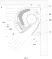
- an air inlet of a wall-mounted air conditioner 1' is located at its top, and the top of the wall-mounted air conditioner 1' has to be at a large distance from an indoor top wall 3, to define an air inflow space. Consequently, the wall-mounted air conditioner 1' cannot be arranged tightly against the indoor top wall 3.
- a heat exchanger 10' of the wall-mounted air conditioner 1' is arranged around a cross-flow fan wheel 20'. Specifically, a first part 11' of the heat exchanger 10', which forms a roughly inverted V-shape, is located above the cross-flow fan wheel 20', and a second part 12' of the heat exchanger 10' is located in front of the cross-flow fan wheel 20'.
- a water receiving tray 30' is provided below a rear lower end 111' of the first part 11'.
- the water receiving plate 30' is opposite to the rear lower end 111' of the first part 11' in an up-down direction and is located between the rear lower end 111' of the first part 11' and the cross-flow fan wheel 20'.
- the inventors have realized that the rear lower end 111' of the first part 11' is obstructed by the water receiving tray 30', such that the rear lower end 111' of the first part 11' does not exchange heat with air, resulting in waste and lowering heat transfer efficiency.
- An inlet air duct 50' is formed between the second part 12' and a front panel 40' of the wall-mounted air conditioner 1'.
- the inventors have realized that since most of the space in a front-rear direction of the wall-mounted air conditioner 1' is occupied by the heat exchanger 10', the cross-flow fan wheel 20' and a volute 60', the inlet air duct 50' is relatively narrow, resulting in a small air flow volume through the inlet air duct 50' and a low heat transfer efficiency of the second part 12'.
- the wall-mounted air conditioner 1 according to embodiments of the present invention will be described below.
- the wall-mounted air conditioner 1 according to embodiments of the present invention comprises a housing 10 and a heat exchanger 20 arranged inside the housing 10.
- the air duct 30 has an air inlet 311 and an air outlet 312, and at least a part of the air inlet 311 is located on a front surface 11 of the housing 10.
- the front surface 11 of the housing 10 is a surface that can be seen by a horizontal backward line of sight, that is, a surface of the housing 10 that can be seen by the horizontal backward line of sight is the front surface 11 of the housing 10.
- a surface of the housing 10 that the observer can see is the front surface 11 of the housing 10.
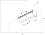
- a front-rear direction is shown by arrow A in FIG. 1
- an up-down direction is shown by arrow B in FIG. 1
- the wall-mounted air conditioner 1 is mounted on a wall surface 2.
- a direction away from the wall surface 2 in the horizontal direction represents a forward direction
- a direction away from the wall surface 2 in the horizontal direction represents a rearward direction.
- ambient air can enter the air duct 30 substantially from the front of the housing 10.
- the ambient air may enter the air duct 30 from the straight front of the housing 10, or may enter the air duct 30 from the top front of the housing 10, or may enter the air duct 30 from the bottom front of the housing 10.
- the ambient air can enter the air duct 30 from at least two directions selected from the straight front of the housing10, the top front of the housing 10, or from the bottom front of the housing 10.
- the ambient air does not necessarily enter the air duct 30 directly above the housing 10.
- a distance between the wall-mounted air conditioner 1 and an indoor top wall 3 can be greatly decreased or even eliminated, and the utilization rate of indoor space can be improved, especially for indoor space (rooms) with lower heights, which can effectively reduce or eliminate a sense of crampedness of the indoor space.
- the wall-mounted air conditioner 1 according to embodiments of the present invention has a very low requirement for mounting space. As long as the wall-mounted air conditioner 1 can be accommodated in the mounting space, there is no need to leave an air inflow space above the wall-mounted air conditioner 1, which can expand the applicability of the wall-mounted air conditioner 1.
- the air inlet 311 is located on the front surface, inclined upwards towards the wall surface 2 (which can be understood as a mounting surface) relative to a vertical surface. In this way, when a user standing on the ground of the room, the user cannot see the interior of the housing 10 (the wall-mounted air conditioner 1) through the air inlet 311, and internal structures of the housing 10 (the wall-mounted air conditioner 1) are not exposed to the user, which can improve the user's visual comfort.
- the top space is often restricted and relatively narrow, which limits the air inflow volume due to the narrow top space.
- the air inlet 311 since at least a part of the air inlet 311 is located on the front surface 11 of the housing 10, the air entering the air duct 30 through the air inlet 311 can directly flow through the heat exchanger 20 for sufficient heat exchange with the heat exchanger 20. That is, the air inflow volume of the wall-mounted air conditioner 1 is not limited by the narrow space at the top.
- the air inflow from the front surface 11 of the housing 10 can effectively increase the air inflow volume and significantly increase the air flow volume through the heat exchanger 20, greatly enhancing the heat exchange efficiency of the heat exchanger 20.
- the air inlet 311 since at least a part of the air inlet 311 is located on the front surface 11 of the housing 10, there is no need to mount a roughly inverted V-shaped heat exchanger below the air inlet 311, and it is unnecessary to mount a water receiving tray with a width greater than or equal to a width of the roughly inverted V-shaped heat exchanger at a lower end of the heat exchanger, to avoid failure in heat exchange of air with a part of the heat exchanger 20 due to the part being obstructed by the water receiving tray. Since at least a part of the air inlet 311 is located on the front surface 11 of the housing 10, the water receiving tray 50 will not prevent airflow from flowing to the heat exchanger 20. For example, the water receiving tray 50 does not pass an airflow path to the heat exchanger 20, which can greatly improve the heat exchange efficiency of the heat exchanger 20. In an embodiment, the water receiving tray 50 is located below the heat exchanger 20.
- the wall-mounted air conditioner 1 in the embodiments of the present invention has advantages of easy installation, improved indoor space utilization, wide applicability, and high heat exchange efficiency.
- the wall-mounted air conditioner 1 according to the embodiments of the present invention comprises the housing 10 and the heat exchanger 20.
- the housing 10 may be mounted on the wall surface 2 indoors.
- a distance between a top surface of the housing 10 and the indoor top wall 3 is less than or equal to 20 centimeters.
- a minimum distance between the housing 10 and the indoor top wall 3 in the up-down direction is less than or equal to 20 centimeters.
- the distance between the top surface of the housing 10 and the indoor top wall 3 is less than or equal to 15 centimeters. Alternatively, the distance between the top surface of the housing 10 and the indoor top wall 3 is less than or equal to 10 centimeters. Alternatively, the distance between the top surface of the housing 10 and the indoor top wall 3 is less than or equal to 8 centimeters. Alternatively, the distance between the top surface of the housing 10 and the indoor top wall 3 is less than or equal to 5 centimeters. Alternatively, the top surface of the housing 10 is in contact with the indoor top wall 3, i.e., the distance between the top surface of the housing 10 and the indoor top wall 3 is equal to 0 centimeter. Hence, the utilization rate of indoor space can be further improved.
- an upper edge of the front surface 11 of the housing 10 is connected to a rear surface 13 of the housing 10 through the top surface 12 of the housing 10.
- a lower edge of the front surface 11 of the housing 10 is directly connected to the rear surface 13 of the housing 10, or the lower edge of the front surface 11 of the housing 10 is connected to the rear surface 13 of the housing 10 through a bottom surface 14 of the housing 10. In such a way, the appearance of the housing 10 and hence the wall-mounted air conditioner 1 becomes neater and more aesthetic.
- the front surface 11 of the housing 10 is a curved or bent surface that protrudes forwards, which can increase an area of the front surface 11 to provide a larger air inlet 311 on the front surface 11, allowing more air to enter the air duct 30 through the air inlet 311 and improving the air inflow volume of the air inlet 311.
- the wall-mounted air conditioner 1 have an increased air inflow volume and improved air inflow efficiency.
- the front surface 11 configured as the bent surface comprises a plurality of portions arranged along the up-down direction or along the length direction of the air duct 30 (i.e., C direction as shown in FIG. 3 ).
- Each portion may be planar, and adjacent portions are located on different planes.
- Each portion may also be curved. Alternatively, some of these portions are planar, while others are curved.
- the front surface 11 of the housing 10 is an arc-shaped surface that protrudes forwards, which not only allows for a larger air inlet 311 on the front surface 11 to further improve the air inflow volume and air inflow efficiency of the wall-mounted air conditioner 1, but also facilitates the processing and manufacturing of the housing 10.
- the front surface 11 of the housing 10 comprises an upper portion, a lower portion, and an intermediate portion connecting the upper portion and the lower portion. Specifically, an upper edge of the intermediate portion is connected to a lower edge of the upper portion, and a lower edge of the intermediate portion is connected to an upper edge of the lower portion.
- the intermediate portion is an arc-shaped surface
- the upper portion is an inclined surface that tilts backwards and upwards
- the lower portion is an inclined surface that tilts backwards and downwards. That is, the upper and lower portions are inclined surfaces, with the upper portion extending backwards and upwards from the intermediate portion and the lower portion extending backwards and downwards from the intermediate portion.
- the intermediate portion may also be a vertical surface.
- the top surface 12 may be a horizontal surface. That is, the top surface 12 may extend horizontally backwards from the front surface 11, so that the top surface 12 cannot be seen by the horizontal backward line of sight.
- the top surface 12 may also be an inclined surface that tilts backwards and downwards. That is, the top surface 12 may be an inclined surface, and the top surface 12 may extend backwards and downwards from the front surface 11, so that the top surface 12 cannot be seen by the horizontal backward line of sight.
- the bottom surface 14 may be a horizontal surface. That is, the bottom surface 14 may extend horizontally backwards from the front surface 11, so that the bottom surface 14 cannot be seen by the horizontal backward line of sight.
- the bottom surface 14 may also be an inclined surface that tilts backwards and upwards. That is, the bottom surface 14 may be an inclined surface, and the bottom surface 14 may extend backwards and upwards from the front surface 11, so that the bottom surface 14 cannot be seen by the horizontal backward line of sight.
- the front surface 11 of the housing 10 is directly connected to the rear surface 13 of the housing 10, which makes the appearance of the housing 10 and hence the wall-mounted air conditioner 1 more concise.
- the heat exchanger 20 is arranged inside the housing 10.
- the air duct 30 is inside the housing 10 and has the air inlet 311 and the air outlet 312. At least a part of the air inlet 311 is on the front surface 11 of the housing 10, to allow at least part of the air (air inflow) to enter the air duct 30 substantially from front of the housing 10.
- a position of the air outlet 312 is lower than a position of the air inlet 311. In other words, at least a part of the air outlet 312 is below at least a part of the air inlet 311, which makes the structure of the wall-mounted air conditioner 1 more reasonable.
- the heat exchanger 20 is arranged in the air duct 30 and corresponding to the air inlet 311. In such a way, air can flow more directly through the heat exchanger 20, further improving the heat exchange efficiency of the heat exchanger 20 and the wall-mounted air conditioner 1.
- the wall-mounted air conditioner 1 further comprises a fan wheel 40 arranged in the air duct 30, and the heat exchanger 20 is arranged between the air inlet 311 and the fan wheel 40.
- the arrangement of the fan wheel 40 in the air duct 30 can increase the flow volume and velocity of air passing through the heat exchanger 20, to further improve the heat exchange efficiency of the heat exchanger 20 and the wall-mounted air conditioner 1.
- the air duct 30 comprises an inlet air duct 321 and an outlet air duct 322, and the fan wheel 40 is at a junction of the inlet air duct 321 and the outlet air duct 322, which can make the structure of the wall-mounted air conditioner 1 more reasonable.
- a part of the fan wheel 40 is inside the inlet air duct 321, and a remaining part of the fan wheel 40 is inside the outlet air duct 322.
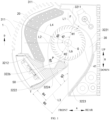
- a projection of the outlet air duct 322 comprises a first side edge 3221 and a second side edge 3222
- a projection of the inlet air duct 321 comprises a first side edge 3211 and a second side edge 3212.
- the length direction of the air duct 30 is shown by arrow C in FIG. 3 .
- the length direction of the air duct 30 may be consistent with the length direction of the wall-mounted air conditioner 1, that is, the length direction of the wall-mounted air conditioner 1 follows the direction of arrow C in FIG. 3 .
- At least a part of the first side edge 3221 is behind at least a part of the second side edge 3222, and at least a part of the first side edge 3211 is above at least a part of the second side edge 3212, which can make the structure of the air duct 30 more reasonable.
- the first side edge 3221 of the projection of the outlet air duct 322 intersects with the first side edge 3211 of the projection of the inlet air duct 321 at a first junction point F, and a rotation axis of the fan wheel 40 intersects with the vertical plane at a base point O.
- a first intersection angle ⁇ 1 between a first connection line L1 between the base point O and the first junction point F and a horizontal line L2 forward from the base point O is greater than or equal to 60 degrees and less than or equal to 150 degrees.
- a first horizontal line passes through the base point O and comprises a front horizontal segment in front of the base point O; and the first intersection angle ⁇ 1 between the front horizontal segment and the first connection line L1 is greater than or equal to 60 degrees and less than or equal to 150 degrees.
- At least a part of an air outlet (an opening of the inlet air duct 321 adjacent to the outlet air duct 322) of the inlet air duct 321 can be opened backwards and downwards, enabling the air in the inlet air duct 321 to enter the outlet air duct 322 more smoothly, thereby improving the cooling and heating effect of the wall-mounted air conditioner 1.
- the first intersection angle ⁇ 1 is greater than or equal to 70 degrees and less than or equal to 130 degrees. Alternatively, the first intersection angle ⁇ 1 is greater than or equal to 80 degrees and less than or equal to 120 degrees. Alternatively, the first intersection angle ⁇ 1 greater than or equal to 90 degrees and less than or equal to 110 degrees. Consequently, the air flowing through the air inlet 311 and the inlet air duct 321 can enter the outlet air duct 322 more smoothly, further improving the cooling and heating effect of the wall-mounted air conditioner 1.
- the first intersection angle ⁇ 1 may be but is not limited to 60 degrees, 65 degrees, 70 degrees, 75 degrees, 80 degrees, 85 degrees, 90 degrees, 92 degrees, 95 degrees, 100 degrees, 102 degrees, 105 degrees, 110 degrees, 115 degrees, 120 degrees, 125 degrees, 130 degrees, 135 degrees, 140 degrees, 145 degrees, or 150 degrees.
- the rotation axis of the fan wheel 40 is perpendicular to the vertical plane.
- the vertical plane is perpendicular to the horizontal plane, and the rotation axis of the fan wheel 40 is parallel to the horizontal plane.
- the first junction point F and an endpoint of the first side edge 3221 away from the air outlet 312 may be the same point.
- a minimum distance H1 between the first side edge 3221 of the projection of the outlet air duct 322 and an outer contour 41 of a projection of the fan wheel 40 is greater than or equal to 4 millimeters and less than or equal to 8 millimeters.
- the air flow volume through the outlet air duct 322 i.e., the air outflow volume of the outlet air duct 322
- the space occupied by the air duct 30 can be reduced, thereby reducing the space occupied by the wall-mounted air conditioner 1.
- the minimum distance H1 between the first side edge 3221 of the projection of the outlet air duct 322 and the outer contour 41 of the projection of the fan wheel 40 is greater than or equal to 5 millimeters and less than or equal to 7 millimeters. Alternatively, the minimum distance H1 between the first side edge 3221 of the projection of the outlet air duct 322 and the outer contour 41 of the projection of the fan wheel 40 is greater than or equal to 5.5 millimeters and less than or equal to 6.5 millimeters. Alternatively, the minimum distance H1 between the first side edge 3221 of the projection of the outlet air duct 322 and the outer contour 41 of the projection of the fan wheel 40 is greater than or equal to 5.6 millimeters and less than or equal to 5.9 millimeters.
- the air flow volume through the outlet air duct 322 i.e., the air outflow volume of the outlet air duct 322
- the space occupied by the air duct 30 can be reduced, thereby reducing the space occupied by the wall-mounted air conditioner 1.
- the minimum distance H1 between the first side edge 3221 of the projection of the outlet air duct 322 and the outer contour 41 of the projection of the fan wheel 40 may be but is not limited to 4 millimeters, 4.5 millimeters, 5 millimeters, 5.5 millimeters, 5.6 millimeters, 5.7 millimeters, 5.75 millimeters, 5.8 millimeters, 5.9 millimeters, 6 millimeters, 6.5 millimeters, 7 millimeters, 7.5 millimeters, or 8 millimeters.
- the minimum distance H1 between the first side edge 3221 of the projection of the outlet air duct 322 and the outer contour 41 of the projection of the fan wheel 40 refers to a minimum distance between any point on the first side edge 3221 and any point on the outer contour 41.
- a second intersection angle ⁇ 2 between a centerline L3 of the outlet air duct 322 and a centerline L4 of the inlet air duct 321 is greater than or equal to 10 degrees and less than or equal to 85 degrees. It is possible to avoid significant changes in a flow direction of air in the air duct 30, in order to reduce flow resistance against the air and allow the air to flow smoothly in the air duct 30, further improving the cooling and heating effect of the wall-mounted air conditioner 1.
- the second intersection angle ⁇ 2 is greater than or equal to 20 degrees and less than or equal to 80 degrees. Alternatively, the second intersection angle ⁇ 2 is greater than or equal to 40 degrees and less than or equal to 75 degrees. Alternatively, the second intersection angle ⁇ 2 is greater than or equal to 60 degrees and less than or equal to 75 degrees. Alternatively, the second intersection angle ⁇ 2 is greater than or equal to 70 degrees and less than or equal to 75 degrees. Consequently, the air can flow more smoothly in the air duct 30, and the cooling and heating effect of the wall-mounted air conditioner 1 can be further improved.
- the second intersection angle ⁇ 2 may be but is not limited to 10 degrees, 15 degrees, 20 degrees, 25 degrees, 30 degrees, 35 degrees, 40 degrees, 45 degrees, 50 degrees, 55 degrees, 60 degrees, 65 degrees, 70 degrees, 71 degrees, 72 degrees, 73 degrees, 74 degrees, 75 degrees, 76 degrees, 77 degrees, 78 degrees, 79 degrees, 80 degrees, or 85 degrees.
- a third intersection angle ⁇ 3 between the centerline L3 of the outlet air duct 322 and a vertical upward direction is greater than or equal to 120 degrees and less than or equal to 155 degrees.
- the vertical upward direction is as indicated by arrow D in FIG. 1 .
- the air leaving the outlet air duct 322 can flow downwards and forwards, that is, the wall-mounted air conditioner 1 can discharge cold air (hot air) downwards and forwards, which can further improve the cooling and heating effect of the wall-mounted air conditioner 1.
- a left-right direction is as indicated by arrow E in FIG. 3 .
- Electric control components, pipelines, circuits, throttling components and the like can be mounted in the mounting space.
- the third intersection angle ⁇ 3 is greater than or equal to 130 degrees and less than or equal to 150 degrees.
- the third intersection angle ⁇ 3 is greater than or equal to 140 degrees and less than or equal to 145 degrees.
- the flow direction of the cold air (hot air) discharged from the wall-mounted air conditioner 1 can be further optimized to improve the cooling and heating effect of the wall-mounted air conditioner 1.
- the third intersection angle ⁇ 3 may be but is not limited to 120 degrees, 125 degrees, 130 degrees, 135 degrees, 140 degrees, 141 degrees, 142 degrees, 143 degrees, 144 degrees, 145 degrees, 150 degrees, or 155 degrees.
- the first side edge 3221 of the projection of the outlet air duct 322 has a first straight segment 3223 adjacent to the air outlet 312, and the second side edge 3222 of the projection of the outlet air duct 322 has a second straight segment 3224 adjacent to the air outlet 312.
- a fourth intersection angle ⁇ 4 between the second straight segment 3224 and the centerline L3 of the outlet air duct 322 is greater than 0 degree and less than or equal to 30 degrees.
- the air flow volume through the outlet air duct 322 i.e., the air outflow volume of the outlet air duct 322
- the space occupied by the outlet air duct 322 can be reduced, to provide sufficient mounting space in front of and/or behind the outlet air duct 322, allowing the components originally mounted on the side (such as the left side and/or the right side) of the length direction of the air duct 30 to be mounted in the mounting space. Consequently, the length of the wall-mounted air conditioner 1 can be effectively decreased, and the installation difficulty of and space required for the wall-mounted air conditioner 1 can be reduced.
- the fourth intersection angle ⁇ 4 is greater than or equal to 1 degree and less than or equal to 25 degrees. Alternatively, the fourth intersection angle ⁇ 4 is greater than or equal to 2 degrees and less than or equal to 20 degrees. Alternatively, the fourth intersection angle ⁇ 4 is greater than or equal to 3 degrees and less than or equal to 10 degrees. In such a way, the air flow volume through the outlet air duct 322 can be increased, and the mounting space in front of and/or behind the outlet air duct 322 can be enlarged, which can further enhance the cooling and heating effect of the wall-mounted air conditioner 1, decrease the length of the wall-mounted air conditioner 1, and reduce the installation difficulty and space required for the wall-mounted air conditioner 1.
- the fourth intersection angle ⁇ 4 may be but is not limited to 1 degree, 2 degrees, 3 degrees, 4 degrees, 5 degrees, 6 degrees, 7 degrees, 8 degrees, 9 degrees, 10 degrees, 15 degrees, 20 degrees, 25 degrees, or 30 degrees.
- a fifth intersection angle ⁇ 5 between the first straight segment 3223 and the second straight segment 3224 is greater than or equal to 5 degrees and less than or equal to 45 degrees.
- the fifth intersection angle ⁇ 5 is greater than or equal to 10 degrees and less than or equal to 40 degrees. Alternatively, the fifth intersection angle ⁇ 5 is greater than or equal to 10 degrees and less than or equal to 30 degrees. Alternatively, the fifth intersection angle ⁇ 5 is greater than or equal to 10 degrees and less than or equal to 20 degrees. In such a way, the air flow volume through the outlet air duct 322 can be increased, and the mounting space in front of and/or behind the outlet air duct 322 can be enlarged, which can further enhance the cooling and heating effect of the wall-mounted air conditioner 1, decrease the length of the wall-mounted air conditioner 1, and reduce the installation difficulty and space required for the wall-mounted air conditioner 1.
- the fifth intersection angle ⁇ 5 may be but is not limited to 5 degrees, 10 degrees, 11 degrees, 12 degrees, 13 degrees, 14 degrees, 15 degrees, 16 degrees, 17 degrees, 18 degrees, 19 degrees, 20 degrees, 25 degrees, 30 degrees, 35 degrees, 40 degrees, or 45 degrees.
- the first side edge 3221 of the projection of the outlet air duct 322 intersects with the first side edge 3211 of the projection of the inlet air duct 321 at the first junction point F
- the second side edge 3222 of the projection of the outlet air duct 322 intersects with the second side edge 3212 of the projection of the inlet air duct 321 at a second junction point P.
- the rotation axis of the fan wheel 40 intersects with the vertical plane at the base point O.
- a line connecting the base point O with the first junction point F is the first connection line L1; a line connecting the base point O with the second junction point P is a second connection line L6; and a sixth intersection angle ⁇ 6 between the first connection line L1 and the second connection line L6 is greater than or equal to 120 degrees and less than or equal to 200 degrees.
- the air inlet of the outlet air duct 322 have a larger inlet angle, to allow more air to enter the outlet air duct 322 and ensure a larger air flow volume in the outlet air duct 322.
- the wall-mounted air conditioner 1 can have a larger air outflow volume, further improving the cooling and heating effect of the wall-mounted air conditioner 1.
- the sixth intersection angle ⁇ 6 is greater than or equal to 130 degrees and less than or equal to 190 degrees. Alternatively, the sixth intersection angle ⁇ 6 is greater than or equal to 140 degrees and less than or equal to 180 degrees. Alternatively, the sixth intersection angle ⁇ 6 is greater than or equal to 155 degrees and less than or equal to 175 degrees. In such a way, it is possible to ensure the large air flow volume through the outlet air duct 322 and the large air outflow volume of the wall-mounted air conditioner 1, thereby further improving the cooling and heating effect of the wall-mounted air conditioner 1.
- the sixth intersection angle ⁇ 6 may be a suction angle of the fan wheel 40.
- the sixth intersection angle ⁇ 6 may be but is not limited to 120 degrees, 125 degrees, 130 degrees, 135 degrees, 140 degrees, 145 degrees, 150 degrees, 152 degrees, 155 degrees, 157 degrees, 160 degrees, 162 degrees, 165 degrees, 167 degrees, 170 degrees, 172 degrees, 175 degrees, 180 degrees, 185 degrees, 190 degrees, 195 degrees, or 200 degrees.
- the second side edge 3222 of the projection of the outlet air duct 322 comprises an arc-shaped segment 3226, and the arc-shaped segment 3226 is concentric with the outer contour 41 of the projection of the fan wheel 40.
- the structure of the air duct 30 is more reasonable.
- any point of the arc-shaped segment 3226 is equidistant from the outer contour 41 of the projection of the fan wheel 40.
- a distance between any point on the arc-shaped segment 3226 and the outer contour 41 the projection of the fan wheel 40 refers to a minimum distance between any point on the arc-shaped segment 3226 and any point on the outer contour 41.
- a distance H2 between the arc-shaped segment 3226 and the outer contour 41 of the projection of the fan wheel 40 is greater than or equal to 4 millimeters and less than or equal to 9 millimeters. It is possible to allow air to enter the outlet air duct 322 more smoothly and achieve a large air flow volume in the outlet air duct 322. Hence, the wall-mounted air conditioner 1 can have a larger air outflow volume, further improving the cooling and heating effect of the wall-mounted air conditioner 1.
- the distance H2 between the arc-shaped segment 3226 and the outer contour 41 the projection of the fan wheel 40 is greater than or equal to 6 millimeters and less than or equal to 8 millimeters.
- the distance H2 between the arc-shaped segment 3226 and the outer contour 41 the projection of the fan wheel 40 is greater than or equal to 7.1 millimeters and less than or equal to 7.9 millimeters. It is possible to allow air to enter the outlet air duct 322 more smoothly and achieve a large air flow volume in the outlet air duct 322.
- the wall-mounted air conditioner 1 can have a larger air outflow volume, further improving the cooling and heating effect of the wall-mounted air conditioner 1.
- the distance H2 between a volute tongue 327 and the fan wheel 40 may be but is not limited to 4 mm, 4.5 mm, 5 mm, 5.5 mm, 6 mm, 6.5 mm, 7 mm, 7.1 mm, 7.2 mm, 7.3 mm, 7.4 mm, 7.5 mm, 7.6 mm, 7.7 mm, 7.8 mm, 7.9 mm, 8 mm, 8.5 mm or 9 mm.
- first and second are used herein for purposes of description and are not intended to indicate or imply relative importance or significance or to imply the number of indicated technical features.
- the feature defined with “first” and “second” may comprise one or more of this feature.
- the term “a plurality of” means at least two, such as two or three, unless specified otherwise.
- the terms “mounted,” “connected,” “coupled,” “fixed” and the like are used broadly, and may be, for example, fixed connections, detachable connections, or integral connections; may also be mechanical or electrical connections; may also be direct connections or indirect connections via intervening structures; may also be inner communication or interaction of two elements, which can be understood by those skilled in the art according to specific situations.
- a structure in which a first feature is "on" or “below” a second feature may include an embodiment in which the first feature is in direct contact with the second feature, and may also include an embodiment in which the first feature and the second feature are not in direct contact with each other, but are contacted via an additional feature formed therebetween.
- a first feature "on,” “above,” or “on top of” a second feature may include an embodiment in which the first feature is right or obliquely “on,” “above,” or “on top of” the second feature, or just means that the first feature is at a height higher than that of the second feature; while a first feature “below,” “under,” or “on bottom of” a second feature may include an embodiment in which the first feature is right or obliquely “below,” “under,” or “on bottom of” the second feature, or just means that the first feature is at a height lower than that of the second feature.
Landscapes
- Engineering & Computer Science (AREA)
- Chemical & Material Sciences (AREA)
- Combustion & Propulsion (AREA)
- Mechanical Engineering (AREA)
- General Engineering & Computer Science (AREA)
- Physics & Mathematics (AREA)
- Thermal Sciences (AREA)
- Air Filters, Heat-Exchange Apparatuses, And Housings Of Air-Conditioning Units (AREA)
- Air-Conditioning Room Units, And Self-Contained Units In General (AREA)
- Structures Of Non-Positive Displacement Pumps (AREA)
- Devices For Blowing Cold Air, Devices For Blowing Warm Air, And Means For Preventing Water Condensation In Air Conditioning Units (AREA)
Applications Claiming Priority (2)
| Application Number | Priority Date | Filing Date | Title |
|---|---|---|---|
| CN202110611174.1A CN115435388A (zh) | 2021-06-01 | 2021-06-01 | 壁挂式空调器 |
| PCT/CN2022/075656 WO2022252677A1 (zh) | 2021-06-01 | 2022-02-09 | 壁挂式空调器 |
Publications (2)
| Publication Number | Publication Date |
|---|---|
| EP4317809A1 true EP4317809A1 (de) | 2024-02-07 |
| EP4317809A4 EP4317809A4 (de) | 2024-09-25 |
Family
ID=84271852
Family Applications (1)
| Application Number | Title | Priority Date | Filing Date |
|---|---|---|---|
| EP22814726.0A Pending EP4317809A4 (de) | 2021-06-01 | 2022-02-09 | Wandmontierte klimaanlage |
Country Status (9)
| Country | Link |
|---|---|
| US (1) | US20240247815A1 (de) |
| EP (1) | EP4317809A4 (de) |
| JP (1) | JP2024517145A (de) |
| KR (1) | KR20230164141A (de) |
| CN (1) | CN115435388A (de) |
| AU (1) | AU2022286271B2 (de) |
| BR (1) | BR112023024670A2 (de) |
| CA (1) | CA3219856A1 (de) |
| WO (1) | WO2022252677A1 (de) |
Families Citing this family (1)
| Publication number | Priority date | Publication date | Assignee | Title |
|---|---|---|---|---|
| CN117366852A (zh) * | 2023-11-21 | 2024-01-09 | 珠海格力电器股份有限公司 | 换热组件及空调 |
Family Cites Families (28)
| Publication number | Priority date | Publication date | Assignee | Title |
|---|---|---|---|---|
| EP0668473B1 (de) * | 1994-02-21 | 2001-04-04 | Kabushiki Kaisha Toshiba | Maschine zur Luftklimatisierung |
| JPH07293934A (ja) * | 1994-04-20 | 1995-11-10 | Fujitsu General Ltd | 空気調和機 |
| TW299019U (en) * | 1995-03-07 | 1997-02-21 | Tokyo Shibaura Electric Co | Indoor units of airconditioner |
| JPH10311552A (ja) * | 1997-05-12 | 1998-11-24 | Hitachi Ltd | 空気調和機室内ユニット |
| JP3497073B2 (ja) * | 1998-01-19 | 2004-02-16 | 三菱電機株式会社 | 貫流送風機 |
| KR20020023532A (ko) * | 2000-09-22 | 2002-03-29 | 구자홍 | 분리형 공기조화기의 실내기 |
| AU767078B2 (en) * | 2000-09-29 | 2003-10-30 | Mitsubishi Denki Kabushiki Kaisha | Air conditioner |
| JP2003202119A (ja) * | 2002-01-08 | 2003-07-18 | Hitachi Ltd | 空気調和機 |
| ITVI20020154A1 (it) * | 2002-07-10 | 2004-01-12 | Xiang Srl | Condizionatore d'aria monoblocco |
| KR100781215B1 (ko) * | 2003-11-28 | 2007-12-03 | 샤프 가부시키가이샤 | 공기 조화기 |
| KR20050058125A (ko) * | 2003-12-11 | 2005-06-16 | 주식회사 대우일렉트로닉스 | 보조 흡기수단을 가지는 분리형 에어컨 |
| JP4799170B2 (ja) * | 2005-12-22 | 2011-10-26 | シャープ株式会社 | 空気調和機の室内機 |
| WO2007083501A1 (ja) * | 2006-01-20 | 2007-07-26 | Sharp Kabushiki Kaisha | 空気調和機 |
| KR20080010682A (ko) * | 2006-07-27 | 2008-01-31 | 주식회사 대우일렉트로닉스 | 승강식 유동가이드유닛을 구비한 벽걸이형 에어컨 |
| JP2008070110A (ja) * | 2007-10-19 | 2008-03-27 | Mitsubishi Electric Corp | 空気調和機 |
| EP2463599B1 (de) * | 2009-08-05 | 2019-05-08 | Mitsubishi Electric Corporation | Klimaanlage zum aufhängen an der wand |
| JP2012083104A (ja) * | 2012-01-30 | 2012-04-26 | Fujitsu General Ltd | 空気調和機 |
| JP2015124986A (ja) * | 2013-12-27 | 2015-07-06 | ダイキン工業株式会社 | 空調室内機 |
| WO2016067408A1 (ja) * | 2014-10-30 | 2016-05-06 | 三菱電機株式会社 | 空気調和機 |
| CN104848420B (zh) * | 2015-04-30 | 2018-07-13 | 武汉海尔电器股份有限公司 | 一种壁挂式空调器 |
| CN106403011B (zh) * | 2015-07-30 | 2019-02-05 | 青岛海尔空调器有限总公司 | 一种具有空气净化功能的壁挂式空调器 |
| CN106369673A (zh) * | 2016-09-09 | 2017-02-01 | 海信科龙电器股份有限公司 | 一种壁挂式空调室内机及其送风方法 |
| CN107166496A (zh) * | 2017-06-30 | 2017-09-15 | 广东美的环境电器制造有限公司 | 风道组件和暖风机 |
| CN110617552A (zh) * | 2019-10-30 | 2019-12-27 | 海信(广东)空调有限公司 | 一种贯流风道的蜗舌结构、风道系统及空调室内机 |
| CN215372681U (zh) * | 2021-06-01 | 2021-12-31 | 广东美的暖通设备有限公司 | 壁挂式空调器 |
| CN215372682U (zh) * | 2021-06-01 | 2021-12-31 | 广东美的暖通设备有限公司 | 壁挂式空调器 |
| CN216897514U (zh) * | 2021-06-01 | 2022-07-05 | 广东美的暖通设备有限公司 | 壁挂式空调器 |
| JP7818493B2 (ja) * | 2022-10-18 | 2026-02-20 | 株式会社日立製作所 | エレベーター |
-
2021
- 2021-06-01 CN CN202110611174.1A patent/CN115435388A/zh active Pending
-
2022
- 2022-02-09 US US18/563,910 patent/US20240247815A1/en active Pending
- 2022-02-09 AU AU2022286271A patent/AU2022286271B2/en active Active
- 2022-02-09 JP JP2023565543A patent/JP2024517145A/ja active Pending
- 2022-02-09 CA CA3219856A patent/CA3219856A1/en active Pending
- 2022-02-09 KR KR1020237037374A patent/KR20230164141A/ko active Pending
- 2022-02-09 WO PCT/CN2022/075656 patent/WO2022252677A1/zh not_active Ceased
- 2022-02-09 BR BR112023024670A patent/BR112023024670A2/pt unknown
- 2022-02-09 EP EP22814726.0A patent/EP4317809A4/de active Pending
Also Published As
| Publication number | Publication date |
|---|---|
| CA3219856A1 (en) | 2022-12-08 |
| BR112023024670A2 (pt) | 2024-02-15 |
| AU2022286271B2 (en) | 2025-09-11 |
| CN115435388A (zh) | 2022-12-06 |
| US20240247815A1 (en) | 2024-07-25 |
| WO2022252677A1 (zh) | 2022-12-08 |
| KR20230164141A (ko) | 2023-12-01 |
| EP4317809A4 (de) | 2024-09-25 |
| JP2024517145A (ja) | 2024-04-19 |
| AU2022286271A1 (en) | 2023-12-07 |
Similar Documents
| Publication | Publication Date | Title |
|---|---|---|
| EP4317809A1 (de) | Wandmontierte klimaanlage | |
| CN107166510B (zh) | 空调室内机 | |
| CN216644347U (zh) | 壁挂式空调器 | |
| EP4317810A1 (de) | Wandmontierte klimaanlage | |
| EP4317826A1 (de) | Wandmontierte klimaanlage | |
| CN110160146B (zh) | 一种空调室内机及空调器 | |
| CN216897514U (zh) | 壁挂式空调器 | |
| EP4317827B1 (de) | Wandmontierte klimaanlage | |
| CN216620017U (zh) | 壁挂式空调器 | |
| CN210292082U (zh) | 一种空调室内机及空调器 | |
| CN216644348U (zh) | 壁挂式空调器 | |
| WO2022252684A1 (zh) | 壁挂式空调器 | |
| CN204629752U (zh) | 空调器 | |
| US12442545B2 (en) | Wall-mounted air conditioner | |
| CN205332477U (zh) | 空调柜机及空调器 | |
| CN216897515U (zh) | 壁挂式空调器 | |
| US20240060658A1 (en) | Wall-mounted air conditioner | |
| CN111322682A (zh) | 空调机 |
Legal Events
| Date | Code | Title | Description |
|---|---|---|---|
| STAA | Information on the status of an ep patent application or granted ep patent |
Free format text: STATUS: THE INTERNATIONAL PUBLICATION HAS BEEN MADE |
|
| PUAI | Public reference made under article 153(3) epc to a published international application that has entered the european phase |
Free format text: ORIGINAL CODE: 0009012 |
|
| STAA | Information on the status of an ep patent application or granted ep patent |
Free format text: STATUS: REQUEST FOR EXAMINATION WAS MADE |
|
| 17P | Request for examination filed |
Effective date: 20231023 |
|
| AK | Designated contracting states |
Kind code of ref document: A1 Designated state(s): AL AT BE BG CH CY CZ DE DK EE ES FI FR GB GR HR HU IE IS IT LI LT LU LV MC MK MT NL NO PL PT RO RS SE SI SK SM TR |
|
| DAV | Request for validation of the european patent (deleted) | ||
| DAX | Request for extension of the european patent (deleted) | ||
| A4 | Supplementary search report drawn up and despatched |
Effective date: 20240822 |
|
| RIC1 | Information provided on ipc code assigned before grant |
Ipc: F24F 13/08 20060101ALI20240817BHEP Ipc: F24F 13/20 20060101ALI20240817BHEP Ipc: F24F 1/0007 20190101AFI20240817BHEP |