EP4317890A1 - Wärmetauscher und klimaanlagensystem - Google Patents
Wärmetauscher und klimaanlagensystem Download PDFInfo
- Publication number
- EP4317890A1 EP4317890A1 EP22778947.6A EP22778947A EP4317890A1 EP 4317890 A1 EP4317890 A1 EP 4317890A1 EP 22778947 A EP22778947 A EP 22778947A EP 4317890 A1 EP4317890 A1 EP 4317890A1
- Authority
- EP
- European Patent Office
- Prior art keywords
- heat exchange
- exchange tube
- tube
- width
- fin
- Prior art date
- Legal status (The legal status is an assumption and is not a legal conclusion. Google has not performed a legal analysis and makes no representation as to the accuracy of the status listed.)
- Pending
Links
Images


Classifications
-
- F—MECHANICAL ENGINEERING; LIGHTING; HEATING; WEAPONS; BLASTING
- F28—HEAT EXCHANGE IN GENERAL
- F28D—HEAT-EXCHANGE APPARATUS, NOT PROVIDED FOR IN ANOTHER SUBCLASS, IN WHICH THE HEAT-EXCHANGE MEDIA DO NOT COME INTO DIRECT CONTACT
- F28D7/00—Heat-exchange apparatus having stationary tubular conduit assemblies for both heat-exchange media, the media being in contact with different sides of a conduit wall
- F28D7/16—Heat-exchange apparatus having stationary tubular conduit assemblies for both heat-exchange media, the media being in contact with different sides of a conduit wall the conduits being arranged in parallel spaced relation
- F28D7/163—Heat-exchange apparatus having stationary tubular conduit assemblies for both heat-exchange media, the media being in contact with different sides of a conduit wall the conduits being arranged in parallel spaced relation with conduit assemblies having a particular shape, e.g. square or annular; with assemblies of conduits having different geometrical features; with multiple groups of conduits connected in series or parallel and arranged inside common casing
- F28D7/1653—Heat-exchange apparatus having stationary tubular conduit assemblies for both heat-exchange media, the media being in contact with different sides of a conduit wall the conduits being arranged in parallel spaced relation with conduit assemblies having a particular shape, e.g. square or annular; with assemblies of conduits having different geometrical features; with multiple groups of conduits connected in series or parallel and arranged inside common casing the conduit assemblies having a square or rectangular shape
-
- F—MECHANICAL ENGINEERING; LIGHTING; HEATING; WEAPONS; BLASTING
- F28—HEAT EXCHANGE IN GENERAL
- F28F—DETAILS OF HEAT-EXCHANGE AND HEAT-TRANSFER APPARATUS, OF GENERAL APPLICATION
- F28F1/00—Tubular elements; Assemblies of tubular elements
- F28F1/02—Tubular elements of cross-section which is non-circular
- F28F1/025—Tubular elements of cross-section which is non-circular with variable shape, e.g. with modified tube ends, with different geometrical features
-
- F—MECHANICAL ENGINEERING; LIGHTING; HEATING; WEAPONS; BLASTING
- F28—HEAT EXCHANGE IN GENERAL
- F28F—DETAILS OF HEAT-EXCHANGE AND HEAT-TRANSFER APPARATUS, OF GENERAL APPLICATION
- F28F1/00—Tubular elements; Assemblies of tubular elements
- F28F1/02—Tubular elements of cross-section which is non-circular
- F28F1/04—Tubular elements of cross-section which is non-circular polygonal, e.g. rectangular
-
- F—MECHANICAL ENGINEERING; LIGHTING; HEATING; WEAPONS; BLASTING
- F28—HEAT EXCHANGE IN GENERAL
- F28D—HEAT-EXCHANGE APPARATUS, NOT PROVIDED FOR IN ANOTHER SUBCLASS, IN WHICH THE HEAT-EXCHANGE MEDIA DO NOT COME INTO DIRECT CONTACT
- F28D1/00—Heat-exchange apparatus having stationary conduit assemblies for one heat-exchange medium only, the media being in contact with different sides of the conduit wall, in which the other heat-exchange medium is a large body of fluid, e.g. domestic or motor car radiators
- F28D1/02—Heat-exchange apparatus having stationary conduit assemblies for one heat-exchange medium only, the media being in contact with different sides of the conduit wall, in which the other heat-exchange medium is a large body of fluid, e.g. domestic or motor car radiators with heat-exchange conduits immersed in the body of fluid
- F28D1/04—Heat-exchange apparatus having stationary conduit assemblies for one heat-exchange medium only, the media being in contact with different sides of the conduit wall, in which the other heat-exchange medium is a large body of fluid, e.g. domestic or motor car radiators with heat-exchange conduits immersed in the body of fluid with tubular conduits
- F28D1/0408—Multi-circuit heat exchangers, e.g. integrating different heat exchange sections in the same unit or heat exchangers for more than two fluids
- F28D1/0426—Multi-circuit heat exchangers, e.g. integrating different heat exchange sections in the same unit or heat exchangers for more than two fluids with units having particular arrangement relative to the large body of fluid, e.g. with interleaved units or with adjacent heat exchange units in common air flow or with units extending at an angle to each other or with units arranged around a central element
-
- F—MECHANICAL ENGINEERING; LIGHTING; HEATING; WEAPONS; BLASTING
- F28—HEAT EXCHANGE IN GENERAL
- F28D—HEAT-EXCHANGE APPARATUS, NOT PROVIDED FOR IN ANOTHER SUBCLASS, IN WHICH THE HEAT-EXCHANGE MEDIA DO NOT COME INTO DIRECT CONTACT
- F28D1/00—Heat-exchange apparatus having stationary conduit assemblies for one heat-exchange medium only, the media being in contact with different sides of the conduit wall, in which the other heat-exchange medium is a large body of fluid, e.g. domestic or motor car radiators
- F28D1/02—Heat-exchange apparatus having stationary conduit assemblies for one heat-exchange medium only, the media being in contact with different sides of the conduit wall, in which the other heat-exchange medium is a large body of fluid, e.g. domestic or motor car radiators with heat-exchange conduits immersed in the body of fluid
- F28D1/04—Heat-exchange apparatus having stationary conduit assemblies for one heat-exchange medium only, the media being in contact with different sides of the conduit wall, in which the other heat-exchange medium is a large body of fluid, e.g. domestic or motor car radiators with heat-exchange conduits immersed in the body of fluid with tubular conduits
- F28D1/047—Heat-exchange apparatus having stationary conduit assemblies for one heat-exchange medium only, the media being in contact with different sides of the conduit wall, in which the other heat-exchange medium is a large body of fluid, e.g. domestic or motor car radiators with heat-exchange conduits immersed in the body of fluid with tubular conduits the conduits being bent, e.g. in a serpentine or zig-zag
- F28D1/0471—Heat-exchange apparatus having stationary conduit assemblies for one heat-exchange medium only, the media being in contact with different sides of the conduit wall, in which the other heat-exchange medium is a large body of fluid, e.g. domestic or motor car radiators with heat-exchange conduits immersed in the body of fluid with tubular conduits the conduits being bent, e.g. in a serpentine or zig-zag the conduits having a non-circular cross-section
-
- F—MECHANICAL ENGINEERING; LIGHTING; HEATING; WEAPONS; BLASTING
- F28—HEAT EXCHANGE IN GENERAL
- F28D—HEAT-EXCHANGE APPARATUS, NOT PROVIDED FOR IN ANOTHER SUBCLASS, IN WHICH THE HEAT-EXCHANGE MEDIA DO NOT COME INTO DIRECT CONTACT
- F28D1/00—Heat-exchange apparatus having stationary conduit assemblies for one heat-exchange medium only, the media being in contact with different sides of the conduit wall, in which the other heat-exchange medium is a large body of fluid, e.g. domestic or motor car radiators
- F28D1/02—Heat-exchange apparatus having stationary conduit assemblies for one heat-exchange medium only, the media being in contact with different sides of the conduit wall, in which the other heat-exchange medium is a large body of fluid, e.g. domestic or motor car radiators with heat-exchange conduits immersed in the body of fluid
- F28D1/04—Heat-exchange apparatus having stationary conduit assemblies for one heat-exchange medium only, the media being in contact with different sides of the conduit wall, in which the other heat-exchange medium is a large body of fluid, e.g. domestic or motor car radiators with heat-exchange conduits immersed in the body of fluid with tubular conduits
- F28D1/053—Heat-exchange apparatus having stationary conduit assemblies for one heat-exchange medium only, the media being in contact with different sides of the conduit wall, in which the other heat-exchange medium is a large body of fluid, e.g. domestic or motor car radiators with heat-exchange conduits immersed in the body of fluid with tubular conduits the conduits being straight
- F28D1/0535—Heat-exchange apparatus having stationary conduit assemblies for one heat-exchange medium only, the media being in contact with different sides of the conduit wall, in which the other heat-exchange medium is a large body of fluid, e.g. domestic or motor car radiators with heat-exchange conduits immersed in the body of fluid with tubular conduits the conduits being straight the conduits having a non-circular cross-section
- F28D1/05366—Assemblies of conduits connected to common headers, e.g. core type radiators
-
- F—MECHANICAL ENGINEERING; LIGHTING; HEATING; WEAPONS; BLASTING
- F28—HEAT EXCHANGE IN GENERAL
- F28F—DETAILS OF HEAT-EXCHANGE AND HEAT-TRANSFER APPARATUS, OF GENERAL APPLICATION
- F28F1/00—Tubular elements; Assemblies of tubular elements
- F28F1/02—Tubular elements of cross-section which is non-circular
- F28F1/022—Tubular elements of cross-section which is non-circular with multiple channels
-
- F—MECHANICAL ENGINEERING; LIGHTING; HEATING; WEAPONS; BLASTING
- F28—HEAT EXCHANGE IN GENERAL
- F28F—DETAILS OF HEAT-EXCHANGE AND HEAT-TRANSFER APPARATUS, OF GENERAL APPLICATION
- F28F1/00—Tubular elements; Assemblies of tubular elements
- F28F1/10—Tubular elements and assemblies thereof with means for increasing heat-transfer area, e.g. with fins, with projections, with recesses
- F28F1/12—Tubular elements and assemblies thereof with means for increasing heat-transfer area, e.g. with fins, with projections, with recesses the means being only outside the tubular element
- F28F1/126—Tubular elements and assemblies thereof with means for increasing heat-transfer area, e.g. with fins, with projections, with recesses the means being only outside the tubular element consisting of zig-zag shaped fins
-
- F—MECHANICAL ENGINEERING; LIGHTING; HEATING; WEAPONS; BLASTING
- F28—HEAT EXCHANGE IN GENERAL
- F28F—DETAILS OF HEAT-EXCHANGE AND HEAT-TRANSFER APPARATUS, OF GENERAL APPLICATION
- F28F2215/00—Fins
- F28F2215/02—Arrangements of fins common to different heat exchange sections, the fins being in contact with different heat exchange media
-
- F—MECHANICAL ENGINEERING; LIGHTING; HEATING; WEAPONS; BLASTING
- F28—HEAT EXCHANGE IN GENERAL
- F28F—DETAILS OF HEAT-EXCHANGE AND HEAT-TRANSFER APPARATUS, OF GENERAL APPLICATION
- F28F2215/00—Fins
- F28F2215/04—Assemblies of fins having different features, e.g. with different fin densities
Definitions
- the present disclosure relates to a field of heat exchangers, and in particular to a heat exchanger and an air conditioning system having the heat exchanger.
- an air conditioner with dual refrigeration systems adopts two separate refrigerant circuits, and a heat exchanger in the refrigerant circuit is a dual system heat exchanger to adapt to the air conditioner with the dual refrigeration systems.
- a heat exchanger in the refrigerant circuit is a dual system heat exchanger to adapt to the air conditioner with the dual refrigeration systems.
- the microchannel heat exchanger in the system is shared by the two systems, and includes flat tube groups working in the two systems respectively, while two parts of heat exchange tubes share a part of fins.
- Embodiments of the present disclosure provide a heat exchanger, which can increase a heat exchange area of a fin and has a good heat exchange performance.
- Embodiments of the present disclosure also provide an air conditioning system using the above heat exchanger.
- the heat exchanger includes: a first assembly including a first tube and a second tube; a second assembly including a third tube and a fourth tube; a plurality of heat exchange tubes, in which the heat exchange tube is a flat tube and includes a plurality of channels extending along a length direction of the heat exchange tube and arranged at intervals in a width direction of the heat exchange tube, and the heat exchange tubes include a first heat exchange tube and a second heat exchange tube; one end of the first heat exchange tube is directly or indirectly connected with the first tube, the other end of the first heat exchange tube is directly or indirectly connected with the third tube, and the first heat exchange tube communicates the first tube with the third tube; one end of the second heat exchange tube is directly or indirectly connected with the second tube, the other end of the second heat exchange tube is directly or indirectly connected with the fourth tube, and the second heat exchange tube communicates the second tube with the fourth tube; and the first heat exchange tube and the second heat exchange tube are arranged at intervals in a length direction of the first tube
- a width W1 of the first heat exchange tube is smaller than a width Wf of the first fin
- a width W2 of the second heat exchange tube is smaller than the width Wf of the first fin
- the width Wf of the first fin is smaller than a sum of the width W1 of the first heat exchange tube and the width W2 of the second heat exchange tube
- a plane perpendicular to the length direction of the first tube is defined as a first plane, and a projection of the first heat exchange tube in the first plane and a projection of the second heat exchange tube in the first plane are at least partially non-coincident.
- the effective heat exchange area of the fin is increased, and the heat exchanger has the good heat exchange performance.
- width directions of the first heat exchange tube and the second heat exchange tube are approximately parallel, and the width W1 of the first heat exchange tube is greater than the width W2 of the second heat exchange tube.
- a smaller one of one third of the width W1 of the first heat exchange tube and one third of the width W2 of the second heat exchange tube is smaller than a width Ws of an overlapping part of the projection of the first heat exchange tube in the first plane and the projection of the second heat exchange tube in the first plane.
- a smaller one of the width W1 of the first heat exchange tube and the width W2 of the second heat exchange tube is larger than a width Ws of an overlapping part of the projection of the first heat exchange tube in the first plane and the projection of the second heat exchange tube in the first plane.
- a minimum distance between a projection of an end of the first heat exchange tube on a side in a width direction of the first heat exchange tube in the first plane and a projection of an end of the first fin on the same side in the width direction in the first plane is WK1, and the distance WK1 is smaller than the width W2 of the second heat exchange tube.
- a minimum distance between a projection of an end of the second heat exchange tube on a side in a width direction of the second heat exchange tube in the first plane and a projection of an end of the first fin on the same side in the width direction in the first plane is WK2
- the distance WK2 is smaller than the width W1 of the first heat exchange tube
- the width W1 of the first heat exchange tube is greater than or equal to the width W2 of the second heat exchange tube.
- a projection of an end of the first heat exchange tube in a width direction of the first heat exchange tube is flush with a projection of one end of the first fin in a width direction of the first fin
- a projection of an end of the second heat exchange tube in a width direction of the second heat exchange tube is flush with a projection of the other end of the first fin in the width direction of the first fin.
- the first heat exchange tube includes a first channel and a second channel, a flow cross-sectional area of the first channel on a cross section of the first heat exchange tube is larger than flow cross-sectional areas of other channels on the cross section of the first heat exchange tube, and a flow cross-sectional area of the second channel on the cross section of the heat exchange tube is smaller than the flow cross-sectional areas of the other channels on the cross section of the first heat exchange tube.
- the second heat exchange tube includes a third channel and a fourth channel, a flow cross-sectional area of the third channel on a cross section of the second heat exchange tube is larger than flow cross-sectional areas of other channels on the cross section of the second heat exchange tube, and a flow cross-sectional area of the fourth channel on the cross section of the second heat exchange tube is smaller than the flow cross-sectional areas of the other channels on the cross section of the second heat exchange tube.
- the heat exchange tube is a microchannel flat tube.
- the air conditioning system includes the heat exchanger according to any one of the above embodiments, and the air conditioning system includes a first circuit and a second circuit.
- the first circuit includes a first compressor and a first throttling device, and the first circuit is communicated with the first tube and the third tube of the heat exchanger.
- the second circuit includes a second compressor and a second throttling device, and the second circuit is communicated with a second tube and a fourth tube of the heat exchanger.
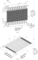
- a heat exchanger 100 includes a first assembly, a second assembly, fins and a plurality of heat exchange tubes 8.
- the first assembly includes a first tube 1 and a second tube 2, and the second assembly includes a third tube 3 and a fourth tube 4.
- the first tube 1, the second tube 2, the third tube 3 and the fourth tube 4 all extend in a front-rear direction, and the first tube 1 and the second tube 2 are located below the third tube 3 and the fourth tube 4.
- the first tube 1 is located right below the third tube 3 and the second tube 2 is located right below the fourth tube 4.
- the heat exchange tube 8 is a microchannel flat tube, and the heat exchange tube 8 includes a plurality of channels 81 extending along its length direction, and the plurality of channels 81 are arranged at intervals in a width direction of the heat exchange tube 8.
- the heat exchange tube 8 is a flat tube, and the length direction of the heat exchange tube 8 is an up-down direction in Fig. 1 .
- the plurality of channels 81 are arranged in the heat exchange tube 8. As shown in Fig.
- the plurality of channels 81 extend along the length direction of the heat exchange tube 8, top ends of the plurality of channels 81 are all communicated with the corresponding third tube 3 or fourth tube 4, and bottom ends of the channels 81 are all communicated with the corresponding first tube 1 or second tube 2.
- the width direction of the heat exchange tube 8 is a left-right direction in Fig. 1 , and as shown in Fig. 4 , the plurality of channels 81 are sequentially arranged at intervals in the left-right direction.
- the heat exchange tube 8 includes a first heat exchange tube 5 and a second heat exchange tube 6.
- One end of the first heat exchange tube 5 is directly or indirectly connected with the first tube 1, and the other end of the first heat exchange tube 5 is directly or indirectly connected with the third tube 3, so that the first heat exchange tube 5 communicates the first tube 1 with the third tube 3.
- One end of the second heat exchange tube 6 is directly or indirectly connected with the second tube 2, and the other end of the second heat exchange tube 6 is directly or indirectly connected with the fourth tube 4, so that the second heat exchange tube 6 communicates the second tube 2 with the fourth tube 4.
- the first heat exchange tube 5 and the second heat exchange tube 6 are arranged at intervals in a length direction of the first tube 1. The first tube is not communicated with the second tube, and the third tube is not communicated with the fourth tube.
- each heat exchange tube 8 is a microchannel flat tube.
- each heat exchange tube 8 is provided with a plurality of channels 81 for the circulation of a cooling medium, the plurality of channels 81 in each heat exchange tube 8 extend along the length direction (the up-down direction in Fig. 1 ) of the heat exchange tube 8, and the plurality of channels 81 in each heat exchange tube 8 are arranged at intervals along the width direction (the left-right direction in Figs. 1 and 2 ) of the heat exchange tube 8.
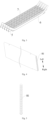
- the heat exchange tube 8 may be divided into the first heat exchange tube 5 and the second heat exchange tube 6 according to different shapes.
- the first heat exchange tube 5 may be a straight tube
- the second heat exchange tube 6 may be a tube bent at both ends and having a straight tube section in the middle.
- a plurality of first heat exchange tubes 5 and a plurality of second heat exchange tubes 6 are provided, and the plurality of first heat exchange tubes 5 and the plurality of second heat exchange tubes 6 are alternately arranged along the length direction of the first tube 1 (the front-rear direction in Fig. 1 ). It should be noted here that "alternately arranged" should be broadly understood.
- one or more second heat exchange tubes 6 may be arranged between two adjacent first heat exchange tubes 5, and one or more first heat exchange tubes 5 may be arranged between two adjacent second heat exchange tubes 6.
- the plurality of first heat exchange tubes 5 may be divided into a plurality of first heat exchange tube groups, and each first heat exchange tube group may include at least two first heat exchange tubes 5.
- the plurality of second heat exchange tubes 6 may be divided into a plurality of second heat exchange tube groups, and each second heat exchange tube group may include at least two second heat exchange tubes 6.
- the first heat exchange tube groups and the second heat exchange tube groups may be alternately arranged.
- the plurality of first heat exchange tubes 5 and the plurality of second heat exchange tubes 6 all extend in the up-down direction, an top end of each first heat exchange tube 5 is communicated with the third tube 3, and a bottom end of each first heat exchange tube 5 is communicated with the first tube 1, so that the cooling medium can flow along the first tube 1, the first heat exchange tube 5 and the third tube 3.
- a top end of each second heat exchange tube 6 is communicated with the fourth tube 4, and a bottom end of each second heat exchange tube 6 is communicated with the second tube 2, so that the cooling medium can flow along the second tube 2, the second heat exchange tube 6 and the third tube 3.
- the fins include first fins 7, and along the length direction of the first tube 1, at least part of the first fins 7 are connected with one first heat exchange tube 5 and the at least part of the first fins 7 are connected with one second heat exchange tube 6.
- the first heat exchange tube 5, the part of the first fins 7 and the second heat exchange tube 6 are arranged along the length direction of the first tube 1. There are two or more first fins 7.
- the fins include a plurality of first fins 7, which are arranged at intervals along the length direction of the first tube 1 (the front-rear direction in Fig. 1 ), and one heat exchange tube is arranged between any two adjacent first fins 7.
- the heat exchange tube 8 may be either the first heat exchange tube 5 or the second heat exchange tube 6.
- the heat exchange tubes 8 on front and rear sides of each first fin 7 may be different.
- the front side of each first fin 7 may be connected to one of the first heat exchange tube 5 and the second heat exchange tube 6, and the rear side of each first fin 7 may be connected to the other of the first heat exchange tube 5 and the second heat exchange tube 6.
- a width W1 of the first heat exchange tube 5 is smaller than a width Wf of the first fin 7
- a width W2 of the second heat exchange tube 6 is smaller than the width Wf of the first fin 7
- the width Wf of the first fin 7 is smaller than a sum of the width W1 of the first heat exchange tube 5 and the width W2 of the second heat exchange tube 6.
- both a width direction of the first heat exchange tube 5 and a width direction of the second heat exchange tube 6 are arranged to extend in the left-right direction.
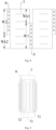
- the widths of the first heat exchange tube 5, the second heat exchange tube 6 and the first fin 7 are W1, W2 and Wf, respectively.
- the width W1 of the first heat exchange tube 5 is smaller than the width Wf of the first fin 7
- the width W2 of the second heat exchange tube 6 is also smaller than the width Wf of the first fin 7
- the sum of the width W1 of the first heat exchange tube 5 and the width W2 of the second heat exchange tube 6 is larger than the width Wf of the first fin 7.
- a plane perpendicular to the length direction of the first tube 1 is defined as a first plane, and a projection of the first heat exchange tube 5 in the first plane is at least partially non-coincident with a projection of the second heat exchange tube 6 in the first plane.
- the first plane is a vertical plane perpendicular to the front-rear direction.
- the first heat exchange tube 5 and the second heat exchange tube 6 are projected into the first plane, and the projection of the first heat exchange tube 5 and the projection of the second heat exchange tube 6 are partially overlapped in the first plane, while partially non-coincident.
- Figs. 9 and 10 show the heat transfer from the heat exchange tube, i.e. the flat tube, to the fins. The farther the fin is from the joint between the heat exchange tube 8 and the fin, the smaller the contribution of the fin to the heat exchange of the heat exchange tube.
- a fin area limited by the width of the flat tube and the height of the fin is a heat affected zone. If only the width of the fin is increased, for example, the width of the fin is greater than the width of the flat tube and the fin protrudes out of the two flat tubes, the fin area in the heat affected zone does not increase significantly, which has little effect on improving the heat transfer performance, but increases the wind resistance on the air side, thus affecting the heat transfer performance.
- two heat exchange tubes are flat tubes.
- the width of the first fin 7 is larger than the widths of the heat exchange tubes 8 on both sides, and when the two heat exchange tubes work at the same time, the first fin 7 shows higher heat flux density in areas adjacent to the heat exchange tubes on both sides.
- a part of the first fin 7 between the heat exchange tubes 8 on both sides may be roughly divided into a first thermal zone 71, a second thermal zone 72 and a third thermal zone 73.
- the first thermal zone 71 is generally located in the middle of the height of the first fin, and the second thermal zone 72 and the third thermal zone 73 are sequentially distributed on one side of the first thermal zone 71.
- the heat flux density of the third thermal zone 73 is higher than the heat flux density of the second thermal zone 72, and the heat of the second thermal zone 72 is higher than the heat of the first thermal zone 71.
- the heat density is relatively small at two ends of the first fin 7 which exceed the heat exchange tube 8.
- the distribution and area of the thermal zone here do not represent the strict location division and area size, but only indicate that there are different trends and laws of heat density distribution.
- the fin in the present disclosure due to the staggered arrangement of the first heat exchange tube 5 and the second heat exchange tube 6 in the width direction of the heat exchange tube, not only the heat exchange area of the fin on the air side is increased, but also the fin area in the heat affected zone of the two heat exchange tubes is significantly increased, which is beneficial to improving the heat exchange between the flat tube and the fin, so that the overall heat exchange performance of the heat exchanger 100 can be improved.
- the first thermal zone 71 of the first fin 7 will be distributed along the width direction of the first heat exchange tube 5 and the second heat exchange tube 6, that is, the first fin 7 covers the entire width direction of the first fin 7, and the second thermal zone 72 and the third thermal zone 73 are located in the areas of the first fin 7 adjacent to the first heat exchange tube 5 and the second heat exchange tube 6, respectively.
- the part of the first fin 7 exceeding the first heat exchange tube 5 or the second heat exchange tube 6 increases the area of the heat affected zone, when the two heat exchange tubes work at the same time, thereby improving the heat exchange performance of the heat exchanger 100.
- the width of the fin increases, the wind resistance will also increase.
- the width of the first heat exchange tube 5 and the width of the second heat exchange tube 6 to be smaller than the width of the fin, and designing the sum of the width of the first heat exchange tube 5 and the width of the second heat exchange tube 6 to be larger than the width of the fin, the width of the fin in the affected area can be increased to improve the amount of heat exchange, and also, the influence on the amount of heat exchange due to the increase of the wind resistance can be reduced, thus improving the heat exchange performance of the heat exchanger 100.
- the heat exchanger 100 when used as an evaporator for a heat pump unit, only one side of the fin on the windward side of the structure in the present disclosure is directly connected with the heat exchange tube 8 under a frosting condition of the heat pump, so that the heat flux density on the windward side is relatively reduced, which is beneficial to reducing the frosting amount on the windward side. Meanwhile, under the condition of ensuring the overall heat exchange capacity of the heat exchanger 100, the frosting layer can be more evenly distributed in the width direction of the fin, which is beneficial to improving the system energy efficiency under the frosting condition.
- the width directions of the first heat exchange tube 5 and the second heat exchange tube 6 are approximately parallel, and the width W1 of the first heat exchange tube 5 is greater than the width W2 of the second heat exchange tube 6.
- the heat exchanger 100 has a windward side and a leeward side during use.
- the first heat exchange tube 5 with the larger width W1 may be installed on the windward side
- the second heat exchange tube 6 with the smaller width W2 may be installed on the leeward side, so that the heat exchange tube with higher heat can be in contact with the air flow first, which is beneficial to improving the heat exchange efficiency.
- the width W2 of the second heat exchange tube 6 may be larger than the width W1 of the first heat exchange tube 5.
- first fin 7 may be a wave-like fin extending along the length direction of the first heat exchange tube 6.
- each fin includes a plurality of sine-shaped fin units 74, and the respective fin units 74 are connected in sequence end to end.
- the fin unit 74 may also be triangular, trapezoidal or the like.
- the first fin 7 may also be a cross-inserted fin or a tube-penetrating fin, the length direction of each fin is parallel to a thickness direction of the first heat exchange tube 5, and the first heat exchange tube 5 and the second heat exchange tube 6 are inserted into the fin for heat exchange.
- the width directions of the first heat exchange tube 5 and the second heat exchange tube 6 may not be parallel, the second heat exchange tube 6 is obliquely inserted into the first fin 7, and its width direction is at an angle with the width direction of the first heat exchange tube 5.
- the width of the heat exchange tube can be increased without excessively increasing the width of the first fin 7, and the heat exchange performance of the heat exchange tube side can be improved while controlling the increase of the wind resistance, which is beneficial to improving the overall performance of the heat exchanger.
- the smaller one of one third of the width W1 of the first heat exchange tube 5 and one third of the width W2 of the second heat exchange tube 6 is smaller than a width Ws of an overlapping part of the projection of the first heat exchange tube 5 in the first plane and the projection of the second heat exchange tube 6 in the first plane.
- the smaller one of the width W1 of the first heat exchange tube 5 and the width W2 of the second heat exchange tube 6 is larger than the width Ws of the overlapping part of the projection of the first heat exchange tube 5 in the first plane and the projection of the second heat exchange tube 6 in the first plane.
- the projection of the first heat exchange tube 5 in the first plane and the projection of the second heat exchange tube 6 in the first plane have the overlapping part, and the width of the overlapping part of the projection of the first heat exchange tube 5 and the projection of the second heat exchange tube 6 in the left-right direction is Ws.
- the smaller one of one third of the width W1 of the first heat exchange tube 5 and one third of the width W2 of the second heat exchange tube 6 is smaller than the above width Ws.
- the smaller one of the width W1 of the first heat exchange tube 5 and the width W2 of the second heat exchange tube 6 is larger than the above width Ws.
- the quantitative design of the width W1 of the first heat exchange tube 5, the width W2 of the second heat exchange tube 6, and the width Ws of the overlapping part of the projection of the first heat exchange tube 5 and the projection of the second heat exchange tube 6 is realized, which ensures that the influence on the amount of heat exchange due to the increase of the effective area of the fin is greater than the decrease of the amount of heat exchange due to the increase of the wind resistance.
- the heat exchange tubes corresponding to the overlapping part of the projections can conduct heat together in the heat affected zone to increase the heat exchange area when the single system works.
- the minimum distance between a projection of an end of the first heat exchange tube 5 on a side in its width direction in the first plane and a projection of an end of the first fin 7 on the same side in the width direction in the first plane is WK1, and the distance WK1 is smaller than the width W2 of the second heat exchange tube 6.
- a left end of the first heat exchange tube 5 is flush with a left end of the first fin 7
- a distance between a right end of the first heat exchange tube 5 and a right end of the first fin 7 is WK1
- the distance WK1 is smaller than the width W2 of the second heat exchange tube 6. Since a side of a section of the fin corresponding to the distance WK1 is directly connected with the second heat exchange tube 6, increasing the length of the distance WK1 can effectively improve the heat exchange capacity of the second heat exchange tube 6. However, another side of the section of the fin corresponding to the distance WK1 is not directly connected with the first heat exchange tube 5, and increasing the distance WK1 will lead to the increase of the wind resistance.
- the distance WK1 is smaller than the width W2 of the second heat exchange tube 6 is beneficial to balancing the relationship between the heat exchange capacity and the wind resistance, especially when the two systems work at the same time, thus improving the overall heat exchange performance.
- this is beneficial to forming an effective heat conduction between the two heat exchange tubes and hence improving the heat exchange capacity of the single system.
- the minimum distance between a projection of an end of the second heat exchange tube 6 on a side in its width direction in the first plane and a projection of an end of the first fin 7 on the same side in the width direction in the first plane is WK2
- the distance WK2 is smaller than the width W1 of the first heat exchange tube 5
- the width W1 of the first heat exchange tube 5 is greater than or equal to the width W2 of the second heat exchange tube 6.
- a right end of the second heat exchange tube 6 is flush with the right end of the first fin 7, the distance between a left end of the second heat exchange tube 6 and the left end of the first fin 7 is WK2, the distance WK2 is smaller than the width W1 of the first heat exchange tube 5, and the width W1 of the first heat exchange tube 5 is not smaller than the width W2 of the second heat exchange tube 6.
- the sum of the flow cross-sectional areas of the channels 81 in the first heat exchange tube 5 is greater than the sum of the flow cross-sectional areas of the channels 81 in the second heat exchange tube 6.
- Both the first heat exchange tube 5 and the second heat exchange tube 6 have a plurality of channels 81.
- the plurality of channels 81 in the first heat exchange tube 5 and the plurality of channels 81 in the second heat exchange tube 6 are arranged at intervals along the left-right direction, and the sum of the flow cross-sectional areas of the plurality of channels 81 in the first heat exchange tube 5 is greater than the sum of the flow cross-sectional areas of the plurality of channels 81 in the second heat exchange tube 6. Therefore, when the heat exchanger 100 is installed, the first heat exchange tube 5 may be installed on the windward side.
- the first heat exchange tube 5 Since the total flow cross-sectional area in the first heat exchange tube 5 is larger and the flow rate of the cooling medium in the first heat exchange tube 5 is larger, the first heat exchange tube 5 has a higher heat exchange performance, the temperature of the air flow after heat exchange by the first heat exchange tube 5 drops, and the air flow with a lower temperature will then flow through the second heat exchange tube 6. Since the flow rate of the cooling medium in the second heat exchange tube 6 is smaller, the cooling of the air flow whose temperature has dropped can be fully met, and this design is beneficial to improving the heat exchange efficiency and reducing the energy consumption.
- a projection of an end of the first heat exchange tube 5 in the width direction is flush with a projection of one end of the first fin 7 in the width direction
- a projection of an end of the second heat exchange tube 6 in the width direction is flush with a projection of the other end of the first fin 7 in the width direction.
- the left end of the first heat exchange tube 5 is flush with the left end of the first fin 7, and the right end of the second heat exchange tube 6 is flush with the right end of the first fin 7. Therefore, the situation that the left and right ends of the first fin 7 exceed the first heat exchange tube 5 and the second heat exchange tube 6 can be avoided, which is beneficial to increasing the total heat on the first fin 7 and is further beneficial to improving the heat exchange efficiency.
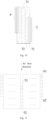
- the first heat exchange tube 5 includes a first channel 51 and a second channel 52, the flow cross-sectional area of the first channel 51 on the cross section of the first heat exchange tube 5 is larger than the flow cross-sectional areas of other channels on the cross section of the first heat exchange tube 5, and the flow cross-sectional area of the second channel 52 on the cross section of the heat exchange tube is smaller than the flow cross-sectional areas of the other channels on the cross section of the first heat exchange tube 5.
- the second heat exchange tube 6 includes a third channel 61 and a fourth channel 62.
- the flow cross-sectional area of the third channel 61 on the cross section of the second heat exchange tube 6 is larger than the flow cross-sectional areas of other channels on the cross section of the second heat exchange tube 6, and the flow cross-sectional area of the fourth channel 62 on the cross section of the second heat exchange tube 6 is smaller than the flow cross-sectional areas of the other channels on the cross section of the second heat exchange tube 6.
- the channels in the first heat exchange tube 5 include the first channel 51 and the second channel 52.
- the flow cross-sectional area of the first channel 51 is larger than the flow cross-sectional area of the second channel 52, and the flow cross-sectional area of the first channel 51 is the largest and the flow cross-sectional area of the second channel 52 is the smallest in the first heat exchange tube 5.
- the first channel 51 is arranged at the right end of the first heat exchange tube 5
- the second channel 52 is arranged at the left end of the first heat exchange tube 5
- the remaining channels in the first heat exchange tube 5 are arranged between the first channel 51 and the second channel 52.
- the channels in the second heat exchange tube 6 include the third channel 61 and the fourth channel 62.
- the flow cross-sectional area of the third channel 61 is larger than the flow cross-sectional area of the fourth channel 62, and the flow cross-sectional area of the third channel 61 is the largest and the flow cross-sectional area of the fourth channel 62 is the smallest in the second heat exchange tube 6.
- the third channel 61 is arranged at the right end of the second heat exchange tube 6, the fourth channel 62 is arranged at the left end of the second heat exchange tube 6, and the remaining channels in the second heat exchange tube 6 are arranged between the third channel 61 and the fourth channel 62.
- the first channel 51 and the third channel 61 may be installed on the windward side, and the second channel 52 and the fourth channel 62 may be installed on the leeward side.
- the first channel 51 and the third channel 61 are arranged on the windward side of the heat exchange tube, have a large heat exchange temperature difference and also have a large flow area at the same time, so that the amount of the refrigerant that can pass through is increased, which is beneficial to improving the heat exchange capacity of the heat exchange tube 8, thus improving the heat exchange capacity of the heat exchanger 100.
- a fin density adjacent to one end of the first fin 7 is different from a fin density adjacent to the other end of the first fin 7.
- the first fin 7 may have a varying density in the width direction of the heat exchange tube, for example, the fin density on the leeward side is large, and the fin density on the windward side is small. Due to the small heat exchange temperature difference and the weak heat exchange capacity on the leeward side, the refrigerant in the channel of the heat exchange tube on the leeward side cannot be fully heat-exchanged. However, the fin density on the leeward side is large to effectively increase the heat exchange area, thus achieving the effect of compensating the heat exchange. In addition, the fin density on the windward side is small and the fin density on the leeward side is large, which is beneficial to improving the frosting performance of the heat exchanger 100.
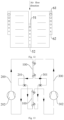
- the air conditioning system includes a first circuit 200, a second circuit 300 and a heat exchanger, and the heat exchanger may be the heat exchanger 100 described in the above embodiments.
- the first circuit 200 is communicated with the first tube 1 and the third tube 3 of the heat exchanger 100, and the first circuit 200 includes a first compressor 202 and a first throttling device 201.
- the second circuit 300 is communicated with the second tube 2 and the fourth tube 4 of the heat exchanger 100, and the second circuit 300 includes a second compressor 302 and a second throttling device 301.
- the first circuit 200 and the second circuit 300 are both closed-loop pipelines.
- the heat exchanger 100 includes the first heat exchange tube and the second heat exchange tube.
- the first circuit 200 includes the first compressor 202 and the first throttling device 201.
- the respective first heat exchange tubes of the two heat exchangers 100 are both connected in series to the first circuit 200.
- the second circuit 300 includes the second compressor 302 and the second throttling device 301, and the respective second heat exchange tubes of the two heat exchangers 100 are both connected in series to the second circuit 300.
- the cooling medium When in use, the cooling medium will circulate along the first circuit 200 and the second circuit 300 respectively.
- the cooling medium flowing out of the first compressor 202 will flow through the first heat exchange tube of one heat exchanger 100, the first throttling device 201, the first heat exchange tube of the other heat exchanger 100 in sequence, and finally flow back into the first compressor 202.
- the cooling medium flowing out of the second compressor 302 will flow through the second heat exchange tube of one heat exchanger 100, the second throttling device 301 and the second heat exchange tube of the other heat exchanger 100 in sequence, and finally flow back into the second compressor 302.
- the heat exchanger 100 of the air conditioning system increases the effective heat exchange area of the fins and improves the heat exchange performance of the air conditioning system.
- microchannel flat tube is a thin-walled, porous, and flat-tubular material made of a refined aluminum rod through hot extrusion and anti-corrosion treatment by spraying zinc on the surface.
- first and second are only used for purpose of description, and cannot be understood as indicating or implying relative importance or implicitly indicating the number of indicated technical features. Therefore, the feature defined as “first” or “second” may explicitly or implicitly include at least one such feature. In the description of the present disclosure, "a plurality of' means at least two, such as two, three, etc., unless otherwise specifically defined.
- install shall be understood broadly, and may be, for example, fixed connections, detachable connections, or integral connections; may also be mechanical or electrical connections or intercommunication; may also be direct connections or indirect connections via intervening media; may also be inner communications or interactions of two elements.
- install shall be understood broadly, and may be, for example, fixed connections, detachable connections, or integral connections; may also be mechanical or electrical connections or intercommunication; may also be direct connections or indirect connections via intervening media; may also be inner communications or interactions of two elements.
- a structure in which a first feature is "on" or “below” a second feature may include an embodiment in which the first feature is in direct contact with the second feature, or may further include an embodiment in which the first feature and the second feature are in indirect contact through intermediate media.
- a first feature "on”, “above”, or “on top of' a second feature may include an embodiment in which the first feature is right or obliquely “on”, “above”, or “on top of' the second feature, or just means that the first feature is at a height higher than that of the second feature
- a first feature "below”, “under”, or “on bottom of” a second feature may include an embodiment in which the first feature is right or obliquely “below”, “under”, or “on bottom of' the second feature, or just means that the first feature is at a height lower than that of the second feature.
Landscapes
- Engineering & Computer Science (AREA)
- Physics & Mathematics (AREA)
- Thermal Sciences (AREA)
- Mechanical Engineering (AREA)
- General Engineering & Computer Science (AREA)
- Geometry (AREA)
- Heat-Exchange Devices With Radiators And Conduit Assemblies (AREA)
Applications Claiming Priority (2)
| Application Number | Priority Date | Filing Date | Title |
|---|---|---|---|
| CN202110335619.8A CN114322105B (zh) | 2021-03-29 | 2021-03-29 | 换热器和空调系统 |
| PCT/CN2022/083733 WO2022206765A1 (zh) | 2021-03-29 | 2022-03-29 | 换热器和空调系统 |
Publications (2)
| Publication Number | Publication Date |
|---|---|
| EP4317890A1 true EP4317890A1 (de) | 2024-02-07 |
| EP4317890A4 EP4317890A4 (de) | 2025-04-02 |
Family
ID=81044311
Family Applications (1)
| Application Number | Title | Priority Date | Filing Date |
|---|---|---|---|
| EP22778947.6A Pending EP4317890A4 (de) | 2021-03-29 | 2022-03-29 | Wärmetauscher und klimaanlagensystem |
Country Status (4)
| Country | Link |
|---|---|
| US (1) | US12510300B2 (de) |
| EP (1) | EP4317890A4 (de) |
| CN (1) | CN114322105B (de) |
| WO (1) | WO2022206765A1 (de) |
Families Citing this family (2)
| Publication number | Priority date | Publication date | Assignee | Title |
|---|---|---|---|---|
| CN118274640A (zh) * | 2022-12-31 | 2024-07-02 | 杭州三花微通道换热器有限公司 | 一种换热装置 |
| CN119737687A (zh) * | 2023-09-25 | 2025-04-01 | 宁波奥克斯电气有限公司 | 一种空调换热组件和空调器 |
Family Cites Families (22)
| Publication number | Priority date | Publication date | Assignee | Title |
|---|---|---|---|---|
| JPH02154987A (ja) * | 1988-12-06 | 1990-06-14 | Matsushita Refrig Co Ltd | フィン付熱交換器 |
| JPH0682188A (ja) * | 1992-09-02 | 1994-03-22 | Nippondenso Co Ltd | 熱交換器 |
| JP2007232246A (ja) | 2006-02-28 | 2007-09-13 | Denso Corp | 熱交換器 |
| US20090154091A1 (en) * | 2007-12-17 | 2009-06-18 | Yatskov Alexander I | Cooling systems and heat exchangers for cooling computer components |
| JP2009145010A (ja) * | 2007-12-17 | 2009-07-02 | Hitachi Appliances Inc | 空気調和機用フィンレス熱交換器 |
| CN101464102A (zh) * | 2009-01-16 | 2009-06-24 | 河北科技大学 | 一种具有较高换热效率的管壳式换热器 |
| CN101738008A (zh) * | 2009-11-30 | 2010-06-16 | 江苏康泰热交换设备工程有限公司 | 一种利于冷凝水排出的热交换器 |
| CN201689278U (zh) | 2009-12-29 | 2010-12-29 | 深圳市锐迪奥科技有限公司 | 用于手机按键渐消工艺的网状菲林 |
| CN102192672A (zh) * | 2010-03-16 | 2011-09-21 | 乐金电子(天津)电器有限公司 | 扁管换热器结构及其装配方法 |
| CN103339457A (zh) * | 2011-01-21 | 2013-10-02 | 大金工业株式会社 | 热交换器及空调装置 |
| JP2014029221A (ja) * | 2012-07-31 | 2014-02-13 | Hitachi Appliances Inc | 空気調和機 |
| JP5853948B2 (ja) * | 2012-12-27 | 2016-02-09 | 株式会社デンソー | 熱交換器 |
| CN108369072B (zh) * | 2015-12-17 | 2020-11-17 | 三菱电机株式会社 | 热交换器和制冷循环装置 |
| US20190249925A1 (en) * | 2016-09-21 | 2019-08-15 | Air-Radiators Pty Ltd | Heat exchanger and components and methods therefor |
| US20180299171A1 (en) * | 2017-04-17 | 2018-10-18 | Lennox Industries Inc. | Multistage, Microchannel Condensers with Displaced Manifolds for Use in HVAC Systems |
| US11047625B2 (en) * | 2018-05-30 | 2021-06-29 | Johnson Controls Technology Company | Interlaced heat exchanger |
| CN111322794A (zh) * | 2018-12-14 | 2020-06-23 | 丹佛斯有限公司 | 换热器和空调系统 |
| CN210128532U (zh) * | 2019-05-31 | 2020-03-06 | 杭州三花微通道换热器有限公司 | 多制冷系统空调机组 |
| CN210689278U (zh) * | 2019-09-29 | 2020-06-05 | 杭州三花微通道换热器有限公司 | 多通道换热器和空调制冷系统 |
| CN212362502U (zh) * | 2020-04-30 | 2021-01-15 | 杭州三花微通道换热器有限公司 | 换热器 |
| CN212457512U (zh) * | 2020-05-31 | 2021-02-02 | 杭州三花微通道换热器有限公司 | 换热组件和换热系统 |
| US11940232B2 (en) * | 2021-04-06 | 2024-03-26 | General Electric Company | Heat exchangers including partial height fins having at least partially free terminal edges |
-
2021
- 2021-03-29 CN CN202110335619.8A patent/CN114322105B/zh active Active
-
2022
- 2022-03-29 US US18/284,904 patent/US12510300B2/en active Active
- 2022-03-29 EP EP22778947.6A patent/EP4317890A4/de active Pending
- 2022-03-29 WO PCT/CN2022/083733 patent/WO2022206765A1/zh not_active Ceased
Also Published As
| Publication number | Publication date |
|---|---|
| CN114322105B (zh) | 2023-07-25 |
| US20240175636A1 (en) | 2024-05-30 |
| CN114322105A (zh) | 2022-04-12 |
| EP4317890A4 (de) | 2025-04-02 |
| WO2022206765A1 (zh) | 2022-10-06 |
| US12510300B2 (en) | 2025-12-30 |
Similar Documents
| Publication | Publication Date | Title |
|---|---|---|
| US12117248B2 (en) | Microchannel flat tube and microchannel heat exchanger | |
| EP3279598B1 (de) | Wärmetauscher und klimaanlage | |
| US20150068244A1 (en) | Heat exchanger and air-conditioning apparatus | |
| US9618269B2 (en) | Heat exchanger with tube arrangement for air conditioner | |
| EP4317890A1 (de) | Wärmetauscher und klimaanlagensystem | |
| WO2020125749A1 (zh) | 换热装置和具有该换热装置的热泵系统 | |
| EP2447660A2 (de) | Wärmetauscher und zugehöriges Mikrokanalrohr | |
| CN205014688U (zh) | 换热器以及换热设备 | |
| CN221527469U (zh) | 微通道换热器、热泵制冷系统及干衣机 | |
| JPWO2005073655A1 (ja) | 熱交換器及びこれを含む空調装置 | |
| JP7006376B2 (ja) | 熱交換器 | |
| CN109579593B (zh) | 翅片、热交换器、换热系统和空调器 | |
| CN110094901B (zh) | 一种微通道换热器 | |
| JP2012154520A (ja) | 熱交換器用チューブ及び熱交換器 | |
| CN218672402U (zh) | 换热器和具有其的空调器 | |
| CN220772012U (zh) | 一种扁管、扁管换热器以及空调 | |
| TWI809718B (zh) | 熱交換器及冷凍循環裝置 | |
| EP1256771A1 (de) | Wärmetauscher | |
| CN216114787U (zh) | 换热器以及空调器 | |
| US12540776B2 (en) | Heat exchanger | |
| JPH08247499A (ja) | 空気調和機の室外機 | |
| CN215345578U (zh) | 散热器 | |
| JP7357773B2 (ja) | 扁平管、マイクロチャネル熱交換器及び空調 | |
| CN112923442B (zh) | 换热器和具有其的空调器 | |
| CN210688491U (zh) | 换热器和具有其的空调器 |
Legal Events
| Date | Code | Title | Description |
|---|---|---|---|
| STAA | Information on the status of an ep patent application or granted ep patent |
Free format text: STATUS: THE INTERNATIONAL PUBLICATION HAS BEEN MADE |
|
| PUAI | Public reference made under article 153(3) epc to a published international application that has entered the european phase |
Free format text: ORIGINAL CODE: 0009012 |
|
| STAA | Information on the status of an ep patent application or granted ep patent |
Free format text: STATUS: REQUEST FOR EXAMINATION WAS MADE |
|
| 17P | Request for examination filed |
Effective date: 20231027 |
|
| AK | Designated contracting states |
Kind code of ref document: A1 Designated state(s): AL AT BE BG CH CY CZ DE DK EE ES FI FR GB GR HR HU IE IS IT LI LT LU LV MC MK MT NL NO PL PT RO RS SE SI SK SM TR |
|
| DAV | Request for validation of the european patent (deleted) | ||
| DAX | Request for extension of the european patent (deleted) | ||
| A4 | Supplementary search report drawn up and despatched |
Effective date: 20250305 |
|
| RIC1 | Information provided on ipc code assigned before grant |
Ipc: F28F 1/02 20060101ALI20250227BHEP Ipc: F28D 1/053 20060101ALI20250227BHEP Ipc: F28F 1/12 20060101AFI20250227BHEP |
|
| GRAP | Despatch of communication of intention to grant a patent |
Free format text: ORIGINAL CODE: EPIDOSNIGR1 |
|
| STAA | Information on the status of an ep patent application or granted ep patent |
Free format text: STATUS: GRANT OF PATENT IS INTENDED |
|
| INTG | Intention to grant announced |
Effective date: 20260213 |
|
| GRAS | Grant fee paid |
Free format text: ORIGINAL CODE: EPIDOSNIGR3 |